Introduction
Dental radiography is the most common radiographic examination, comprising 33% of all medical examinations (Tanner et al. 2000). Radiographs are used in dentistry for many reasons, summarized below:
• To detect pathology associated with teeth and their supporting structures, such as caries, periodontal disease and periapical pathology.
• To detect anomalies/injuries associated with the teeth, their supporting structures, the maxilla and the mandible.
• To determine the presence/absence of teeth and to localize unerupted teeth.
• To measure the length of the roots of teeth before endodontic therapy.
• To detect the presence/absence of radio-opaque salivary calculi and foreign bodies.
• To detect anomalies/injuries/pathology of adjacent facial structures.
• To evaluate skeletal and/or soft tissues before orthodontic treatment.
• To monitor the progression of orthodontic treatment and dental disease.
• To enable a preoperative assessment of skeletal and soft tissue patterns before orthognathic surgery.
• To assess bony healing and effectiveness of surgical treatment of the patient postoperatively.
Dental radiography involves techniques in which the film is placed either inside the mouth (intra-oral radiography) or outside the mouth (extra-oral radiography).
Intra-oral radiography
The most frequently requested intra-oral projections are bitewing radiography, periapical radiography and occlusal radiography.
Bitewing radiography is a lateral view of the posterior regions of the jaws. The view demonstrates the crowns of the teeth and the alveolar crestal bone of the premolar and molar regions of both the maxilla and mandible.
Periapical radiography is a lateral projection displaying both the crown and the root of the tooth and the surrounding bone.
Occlusal radiography comprises a number of views in which the film is positioned in the occlusal plane.
Extra-oral radiography
The most frequently requested extra-oral projections are dental panoramic radiography, oblique lateral radiography and cephalometry.
Dental panoramic radiography is a projection that produces an image of both jaws and their respective dentitions on a single extra-oral film.
Oblique lateral radiography demonstrates large areas of the maxilla and mandible, with the region imaged dependent on the technique chosen.
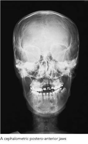
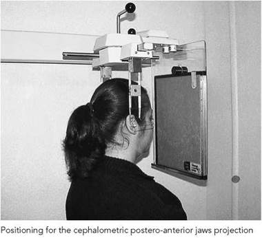
Cephalometry employs techniques to produce standardized and reproducible films of the facial bones for use in orthodontic, orthognathic and implant treatment.

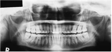
Dental panoramic tomograph of an adult dentate patient
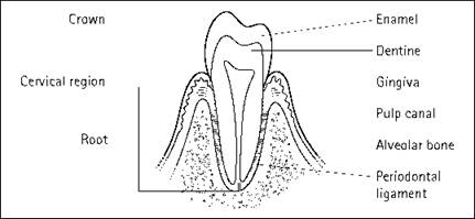
Schematic view of the basic components of the tooth and its supporting tissue
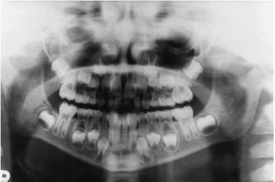
Panoramic radiograph of a child in the mixed-dentition stage of tooth development

Periapical radiograph of the anterior maxilla, illustrating normal radiographic anatomy of the tooth and supporting structures
The dentition
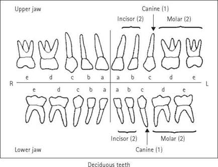
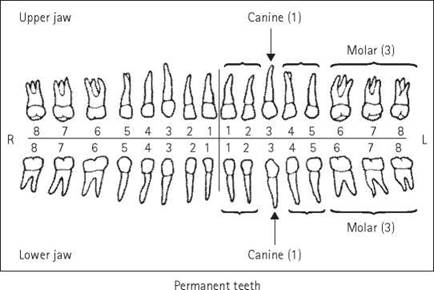
The primary or deciduous dentition comprises 20 teeth, with five in each quadrant of the jaws. These are replaced from six years onwards by a permanent dentition of 32 teeth. With eruption of all 32 permanent teeth, there will be eight permanent teeth in each quadrant. Some teeth may fail to develop or erupt, a complication most commonly affecting the third permanent molars (the wisdom teeth).
From the midline moving posteriorly, the teeth in the anterior part of the jaws comprise the central incisor, the lateral incisor and the canine (cuspid). This terminology is used in both deciduous and permanent dentitions. In the permanent dentition posterior to the canine, there are a first and a second premolar (bicuspid) followed by a first, a second and, if they develop, a third permanent molar. The deciduous dentition differs in that there are only two teeth posterior to the deciduous canine, a first and a second deciduous molar.
Each tooth consists of a variety of hard, mineralized tissues with a central area, the pulp chamber and canal, consisting of blood vessels and nerves supported by loose connective tissue. The part of the tooth that projects above the gingiva (gum) and is evident in the mouth is the crown; the portion embedded within the jaw is known as the root. The constriction between the crown and the root is known as the cervical region.
The outer surface of the crown of the tooth comprises enamel with a less mineralized tissue, dentine, below it. The enamel, containing 96% by weight of inorganic material, is radiographically distinguishable from the dentine, which is 70% mineralized with hydroxyapatite. Enamel is limited to the crown of the tooth, whereas dentine encircles the pulp chamber in the crown of the tooth and extends into the root of the tooth, enveloping the pulp canal. Cementum is a thin layer of bone-like material (50% mineralized with hydroxyapatite) covering the dentine of the root and forming the periphery of the root surface. It is not possible to distinguish radiographically between cementum and dentine. Nerves and nutrient vessels enter the pulp through the root apex.
The tooth, depending on its position in the mouth, may have one or several roots. In the anterior regions of the jaws, in both dentitions, the incisor and canine teeth are single-rooted. The molar teeth, in both dentitions, have several roots. As a generality, in the upper jaw the molar teeth have three roots, whilst in the lower jaw two-rooted molars are the norm. The roots associated with the third permanent molar in both jaws may vary in their number and complexity.
The tooth is supported in its alveolar socket by a periodontal ligament, the fibres of which are embedded in the cementum of the root surface and the surrounding alveolar bone. A thin layer of dense bone encircles the tooth socket. Radiographically, this appears as a linear radio-opacity and is referred to as the lamina dura. The periodontal ligament appears as a uniform (0.4-1.9 mm), linear radio-lucency around the root. In the absence of periodontal disease, the alveolar bone should extend to a point 1.5 mm below the cemento-enamel junction.
Dental formulae
There are several internationally recognized methods of identifying the teeth that require radiography. In those cases in which a patient is edentulous (i.e. no teeth visible within the dental arches), a clinician will continue to use the dental formula to denote the part of the oral cavity requiring radiography.
The two most commonly used methods of notation are:
• Palmer notation; and
• Fédération Dentaire International (FDI) notation.
Palmer notation
This technique is known also by the names Zsigmondy-Palmer system, chevron system and the set square system.
Each dental quadrant extends from the midline of the oral cavity posteriorly and, individually, corresponds to the upper left and right quadrants in the maxilla and the lower left and right quadrants in the mandible.
The Palmer notation is depicted schematically, with a vertical line between the central maxillary and mandibular incisors and a horizontal line between the maxilla and mandible, dividing the oral cavity into quadrants. The clinician requesting intraoral radiography uses these vertical and horizontal lines to denote the quadrant to which the tooth/teeth to be radiographed belong.
To avoid confusion between the permanent and deciduous dentition, the following convention is observed:
• For the deciduous dentition: five teeth in each quadrant are assigned the letters A-E, from the central deciduous incisor to the second deciduous molar, respectively.
• For the permanent dentition: eight teeth in each quadrant are assigned the numbers 1-8, from the central incisor to the third permanent molar, respectively.
The number or letter of the tooth to be radiographed is then added to complete the notation.
Examples of requests for dental examinations using this system are:


Fédération Dentaire International notation
The formula devised by the FDI identifies each tooth using two digits. This method of notation is preferred by some clinicians to avoid the typographical errors that can sometimes affect the Palmer system.
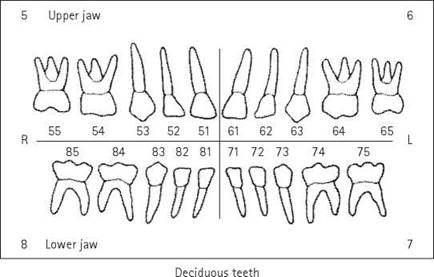
The dentition is again divided into four quadrants. These are assigned the numbers 1-4 for the permanent teeth and the numbers 5-8 for the deciduous dentition. In both dentitions, the quadrants follow on numerically, starting from the upper right, to the upper left, to the lower left and, finally, to the lower right. The number of the quadrant precedes the number of the tooth to be radiographed.
The convention is for individual teeth in either dentition to be numbered sequentially from 1 (for the central incisor) to the most distal molar, i.e. 1-8 in each quadrant in the permanent dentition and 1-5 for the deciduous dentition.
Examples of requests for dental examinations using this formula are:
53 - upper right deciduous canine.
37, 38 - lower left second and third molars.
Terminology
Dentists use the following terms to describe the tooth surfaces:
• Mesial represents that surface of the tooth adjacent to the median plane following the curvature of the dental arch.
• Distal represents that surface of the tooth furthest away from the median plane following the curvature of the dental arch.
• Lingual or palatal refers to the inner aspect of the teeth or dental arches adjacent to the tongue or palate, respectively.
• Buccal or labial refers to the outer aspect of the teeth or dental arches adjacent to the cheeks or lips, respectively.
• Occlusal refers to the biting surface of both premolar and molar teeth.
• Incisal refers to the horizontal flat surface of the incisor teeth.

True occlusal radiograph of the mandible
Occlusal planes
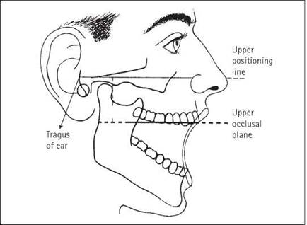
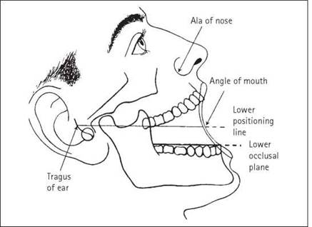
The occlusal plane is the plane that passes through the opposing biting surfaces of the teeth. The terms upper occlusal plane and lower occlusal plane are used in radiographic positioning when carrying out intra-oral radiography.
It is necessary to adjust the position of the patient’s head before intra-oral radiography to ensure that the appropriate occlusal plane is horizontal and the median plane is vertical. Common radiographic centring points are used to achieve these aims with the patient seated and the head supported adequately.
With the mouth open, the upper occlusal plane lies 4 cm below and parallel to a line joining the tragus of the ear to the ala of the nose.
The lower occlusal plane lies 2 cm below and parallel to a line joining the tragus of the ear to the angle of the mouth with the mouth open.

Vertex occlusal radiograph

Patient sitting in dental chair with adjacent intra-oral X-ray. X-ray equipment is fitted with a long, open-ended spacer cone (beam-indicating device)
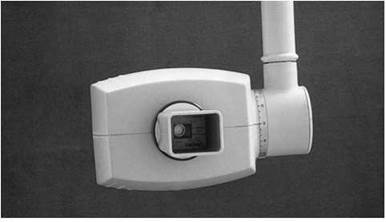
Intra-oral X-ray equipment fitted with metallic rectangular spacer cone
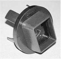
Example of a removable collimator (Dentsply Rinn® Universal collimator)
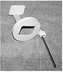
Dentsply Rinn® stainless steel collimator attached by tabs to a Dentsply Rinn XCP® film holder
X-ray equipment features
Dental equipment for intra-oral radiography is designed in order to comply with radiation protection legislation and to ensure that the patient dose is minimized. Such equipment will have the following features:
• X-ray tube potential:
- nominal tube potential not lower than 50 kVp;
- recommended operating range of 60-70 kVp.
• X-ray tube filtration:
- 1.5 mm aluminium equivalent for dental units up to 70 kVp;
- 2.5 mm aluminium equivalent (of which 1.5 mm should be permanent) for dental units over 70kVp.
• X-ray beam dimensions:
- beam diameter at the patient's skin not greater than 60 mm;
- rectangular collimation to be provided on new equipment and retro-fitted to existing equipment.
• Minimum focus-to-skin distance:
- 200 mm for dental units of 60 kVp or greater;
- 100 mm for dental units less than 60 kVp.
Recommended kilovoltage operating range
The use of a higher kilovoltage (60-70 kVp) in dental radiography represents a prudent compromise between minimizing surface dose to the patient and obtaining sufficient contrast to allow radiological diagnosis of dental and bony tissue.
Rectangular collimation
The use of rectangular collimation for intra-oral dental radiography (see figure) has been shown to reduce patient dose by up to 50% compared with a 6-cm round beam.
Rectangular collimation is available as:
• manufactured component of the X-ray tube head;
• 'removable' universal fitting to open-ended cylinder type of equipment;
• additional component of some types of film holders.
Film-holding devices
The use of a film holder, incorporating an extra-oral aiming arm to ensure accurate alignment of the X-ray tube relative to the intra-oral film, is mandatory when using rectangular collimation in order to prevent 'cone-cut' (see p. 290).
Image quality is improved when employing rectangular collimation and longer focus-to-film distance (FFD) by reducing the amount of scattered radiation and reducing the penumbra effect, respectively.
Image receptors
The following types of image receptors are used in dental radiography:
• Intra-oral radiography:
- direct or non-screen film;
- digital receptors.
• Extra-oral radiography:
- film-screen (usually rare-earth);
- digital receptors: storage phosphor and solid-state.
Direct or non-screen film
Dental radiography uses direct film. For the dental clinician, direct (or packet) film has the advantage of producing a high- resolution image that provides the fine detail needed to assess pathological changes.
The contents of the film packet consist of the following:
• Outer plastic wrapper to prevent moisture contamination. The reverse side of the outer wrapper has a two-toned appearance to differentiate it as the non-imaging side of the film packet.
• Black paper that is wrapped around the film to protect it from light ingress and damage during handling.
• Lead foil with an embossed pattern is positioned at the back of the film to reduce film fogging from scattered radiation. If the packet is inadvertently positioned back-to-front, the foil pattern is evident on the processed film, identifying the cause of underexposure.
• A single sheet of film comprising a plastic base with emulsion adherent to both surfaces.
Intra-oral film sizes
Several film sizes are available:
• Size 0 — 22 X 35 mm: used for small children and anterior periapicals using the paralleling technique.
• Size 1 — 24 X 40 mm: used for bitewings in small children and also for anterior projections in adults. Not available routinely in the UK.
• Size 2 — 31 X 41 mm: used for bitewings in adults and older (generally six years plus) children and periapical projections. Can be used for occlusal views in young children.
• Size 4 — 57 X 76 mm: used for occlusal projections of the maxilla and mandible.
Intra-oral film is available in some sizes as double film packets. This enables the practitioner to forward one to, for instance, the insurer funding the treatment whilst retaining the other within the patient's records.
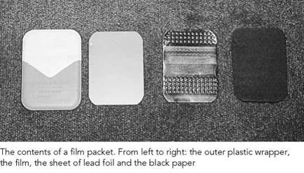
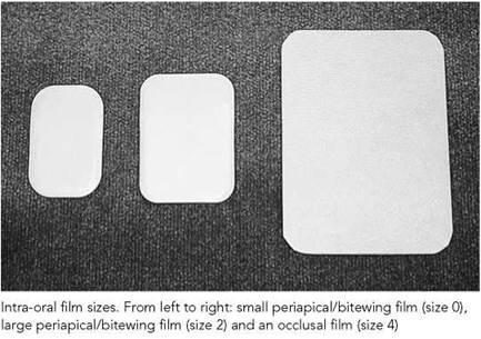

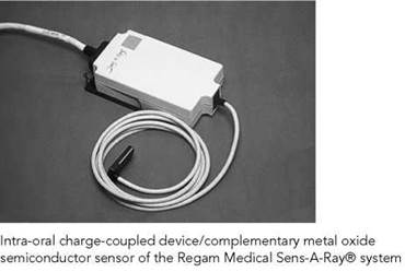
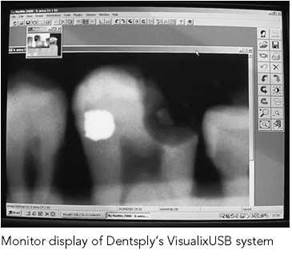
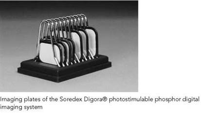
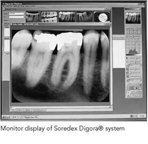
Image receptors
Digital receptors
Many manufacturers are now producing digital imaging systems specifically for dental radiography. The two methods of image capture used are solid-state and storage phosphor:
• Solid state: manufacturers employ a range of electronic sensor technology within digital imaging systems. These include charge-coupled device (CCD)-, charge-injection device (CID)- and complementary metal oxide semiconductor (CMOS)- based sensors. The sensor is linked directly to the computer via a cable. There is an instantaneous image display with these systems.
• Storage phosphor: these systems are commonly found in general radiography departments and may be referred to as computed radiography (CR). Other terms used to describe the technique are photostimulable phosphor radiography (PPR), storage phosphor radiography (SPR) and photostimulable phosphor (PSP). The PSP imaging plates consist of europium- activated barium fluorohalide. When exposed to X-rays, the energy of the incident X-ray beam is stored in valency traps in the phosphor. This latent image of stored energy is released as light following scanning of the exposed plate by a laser beam. The pattern of light released is received and then amplified by a CCD and photomultiplier, respectively. The image is displayed on a monitor.
The advantages of solid-state and storage phosphor systems are:
• instant image in the case of solid-state systems;
• almost instant images with storage phosphors. There is a negligible delay of 20 s as the plate is read by the laser;
• image manipulation.
The advantages of storage phosphor are:
• very wide exposure latitude;
• sensors are identical in size and thickness to the film and are tolerated well by patients.
Disadvantages of solid-state and storage phosphor systems are:
• cost;
• in some solid-state systems, the sensor may have a smaller sensitive area than the film, requiring more exposures to the cover area of interest;
• solid-state sensors are bulky and have an attached cable;
• some imaging systems provide insubstantial intra-oral positioning devices.
Although intra-oral digital dental equipment is becoming more generally available, this chapter will continue to refer to film in the technique sections, since film remains the most frequently used type of image receptor in dental radiography.
Image acquisition
Film-holding instruments and film-holding beam-alignment instruments
These devices have been developed in order to simplify intraoral (bitewing and periapical) radiography for both the operator and the patient. Although bitewing and periapical radiography may be carried out without these devices, research has shown that they noticeably reduce technical errors (Rushton and Horner, 1994; Kaffe et al., 1981).
The devices available are:
• Film-holding instrument: localizes the film intra-orally.
• Film-holding beam-alignment instrument: localizes the film intra-orally and aligns the X-ray tube relative to the film.
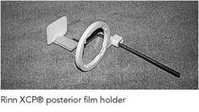
The term 'film holder' is a generic term applied to both instrument types. An ideal film holder must incorporate the following features:
• a bite block to stabilize and locate the device correctly;
• a rigid backing to prevent bending;
• an extra-oral arm (or extension) to ensure correct angulation.
Film-holding beam-alignment instruments are, in most cases, designed with an aiming ring attached to an external indicator rod. This type of device has the advantage of accurate localization. The ring must be positioned in contact with the skin surface to achieve the correct focal spot-to-skin distance.
Specialized film holders
Specialized film holders are available for use in or with:
• endodontic practice;
• periodontal practice;
• digital equipment.
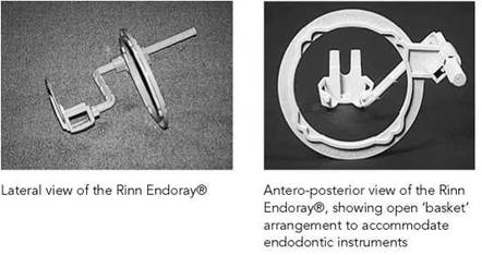
During endodontic treatment, the film-holding beam-aiming instrument allows a working length calculation or enables length determination of a master cone. This is achieved by replacing the dense bite block with an open 'basket' design.
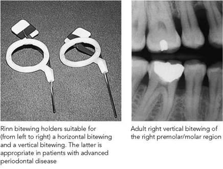
The specialized periodontal film-holding beam-alignment instrument allows assessment of bone loss in advanced periodontal disease by stabilizing the intra-oral film with its long axis vertically.
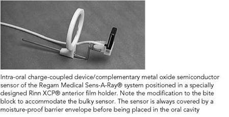
Various manufacturers have produced modified film-holding instruments/film-holding beam-alignment instruments to accommodate bulkier intra-oral digital sensors.

Film mounting and identification of intra-oral films
The embossed dot at one corner of the front of the film packet allows correct film orientation by denoting the front of the film. The radiographer should adopt a working practice of positioning the dental film with this dot towards the crown of the tooth, so that it will not obscure pathology within areas of interest.
Orientation of radiographs of edentulous patients is made easier by adopting the convention of positioning the embossed dot towards the anterior part of the mouth. This technique is also helpful when soft-tissue views have been requested.
Films are mounted with the (embossed) dot towards the radiographer and as though the operator was looking at the patient. This ensures that the mounted films exactly match the dental charting.
• Arrange all films to be mounted on the viewing box.
• Arrange films as to whether they were taken in the maxilla or mandible followed by region, i.e. anterior and posterior. Use anatomical landmarks for guidance as well as root formation.
• Arrange the films of the maxillary teeth by placing the crowns of the teeth towards the bottom of the viewer.
• Arrange the films of the mandibular teeth with the crowns of the teeth towards the top of the viewer.
• When maxillary and mandibular teeth have been identified, radiographs are then arranged as belonging to either the right or left side of the patient.
Radiographs of the anterior incisors are placed in the centre of the mount. The radiographs of the lateral and canine teeth (positioned correctly, according to side) are placed adjacent to them. This is repeated successively for premolars and molar films to complete film mounting in both dental arches.
General comments
Most dental radiographic examinations require the patient to be seated with the head supported and usually with the occlusal plane horizontally positioned and parallel to the floor.
Prior to the examination, the patient's spectacles, orthodontic appliances and partial/full dentures should be removed. Removal of other jewellery such as earrings, necklaces, tongue bars, nose rings, etc., may also be necessary for certain views.
Dental radiography examinations of the mouth may be complicated by a variety of factors, including:
• the patient's medical and dental condition;
• the degree of patient cooperation;
• anatomical factors, e.g. large tongue, shallow palate, narrow dental arches.
Careful film placement, explanation of the procedure and reassuring the patient will reduce the need for repeat radiographs.
Small children often find the equipment very intimidating and need careful reassurance. Elderly patients may find difficulty in maintaining the position for dental radiography, and movement during the exposure may be a problem. Both groups of individuals often benefit from a clear explanation of the procedure and the use of short exposure times.
The X-ray request form should be checked to ensure that the examination has been justified and that the correct film type and equipment are available.
Exposure factors should be set before the examination.
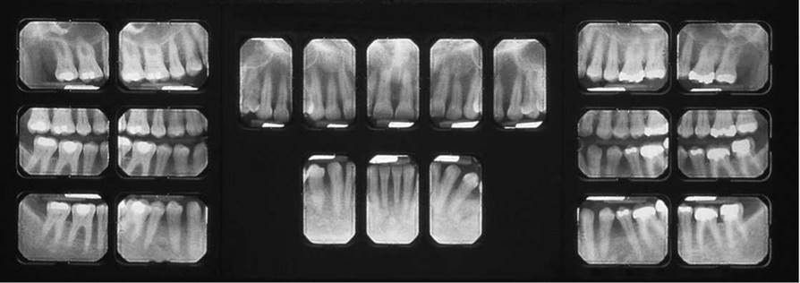
Complete mouth survey taken using the paralleling technique. Both periapical and bitewing radiographs are shown
Radiation protection
Dental radiography is a low-dose but high-volume technique.
The following comprise the basic requirements of radiation protection legislation, as it relates to dental radiography, which has been adopted for dental practice within the UK (National
Radiological Protection Board, 2001):
• Each request for dental radiography must be justified.
• Radiographers must never position themselves in the direction of the primary beam.
• Controlled areas are determined in consultation with the Radiation Protection Adviser.
• The radiographer must never support a film inside the patient's mouth.
• Film holders should be used routinely for intra-oral radiography.
• Quality assurance procedures must be adopted.
• The use of a higher kilovoltage (60-70 kVp) in dental radiography represents a prudent compromise between minimizing surface dose to the patient and obtaining sufficient contrast to allow radiological diagnosis of dental and bony tissue.
• The use of rectangular collimation for intra-oral dental radiography has been shown to reduce patient dose by up to 50% compared with a 6-cm round beam.
• The use of a film holder incorporating an extra-oral aiming arm to ensure accurate alignment of the X-ray tube relative to the intra-oral film is mandatory when using rectangular collimation in order to prevent 'cone-cut'.
• Image quality is improved when employing rectangular collimation and longer FFD by reducing the amount of scattered radiation and reducing the penumbra effect, respectively.
• There is no indication for the routine use of lead aprons in dental radiography. It is well recognized that lead protection for the patient has no demonstrable effect against internal scatter and provides only a practicable degree of protection in the case of the very infrequently used vertex occlusal projection. In this case, the use of a lead apron could only be regarded as prudent for a female patient who is, or may be, pregnant (National Radiological Protection Board, 2001).
Cross-infection control
Dental radiography is not an invasive procedure and is generally considered low-risk for the operator, except when blood is present, e.g. post-extraction, post-trauma.
Since saliva and/or blood can contaminate films and radiographic equipment, meticulous cross-infection control is important:
• The radiographer should wash his/her hands before and after each examination within sight of the patient.
• If the operator has any open wounds on the hands, these should be covered with a dressing.
• Hospital policies vary on the need for gloves to be worn routinely during intra-oral radiography.
• Barrier envelopes for intra-oral films significantly reduce the risk of microbial contamination by saliva and/or blood.
• If barrier envelopes are not available, then exposed film packets should be disinfected before they are handled and processed.
• The use of a disposable tray system containing film packets and film holders significantly reduces contamination of work surfaces.
• Contaminated empty film packets, barrier envelopes, gloves, cotton-wool rolls and disposable tray should be discarded as clinical waste.
• Intra-oral film-holding devices should be sterilized according to the manufacturer's guidelines. Most manufacturers recommend rinsing and steam autoclaving after use. Some filmholding devices are disposable.
• Surface disinfectants should be used on all work surfaces, the dental chair, cassettes, the control panel, the X-ray tube head and the exposure switch after each patient.
• Manufacturers of panoramic equipment may provide individual bite blocks or disposable bite-block covers for each patient. The former are sterilized, whilst the latter are discarded after exposure. Chin rests and head-positioning guides should be cleaned between patients.
• Manufacturers provide disposable barrier envelopes for the sensor in digital imaging systems. The mouse and the keyboard of computers are a potential weak spot in crossinfection control. If you feel that there is a risk from oral fluids, then you should protect these items.
Film processing
Films may be processed both manually and automatically in specially adapted processing machines.
The operator should pay particular attention to careful handling of the film and should ensure that the processing and darkroom techniques employed result in:
• no pressure marks on the film and no emulsion scratches;
• no roller marks (automatic processing only);
• no evidence of film fog;
• no chemical streaks/splashes/contamination;
• no evidence of inadequate fixation/washing.
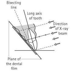
Diagram to show the theoretical basis of the bisecting angle technique

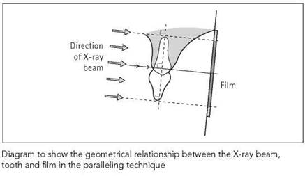
Diagram to show the geometrical relationship between the X-ray beam, tooth and film in the paralleling technique
Principles for optimal image geometry
In order to minimize distortion effects and to achieve optimal image geometry, the following principles have been advocated for intra-oral radiography:
• The focal spot should be as small as possible.
• The focal spot-to-object distance should be as great as possible.
• The object-to-film distance (OFD) should be as small as possible.
• The film should be parallel to the plane of the object.
• The central ray should be perpendicular to both the object and the film.
Both bitewing and periapical radiography benefit from an accurate and stable position of the image receptor.
Bitewing radiography requires that the beam, in the horizontal plane, meets the teeth and the film at right-angles and passes through all the contact areas.
For periapical radiography, the ideal principles for optimal image geometry cannot be satisfied in all patients, due to a variety of factors. To overcome these problems, two techniques have been developed:
• Bisecting angle technique: this is based upon the geometric theorem of isometry. It requires the central ray of the X-ray beam to pass through the root of the tooth at right-angles to a plane that is the bisector of the angle formed by the long axis of the tooth and the plane of the film.
• Paralleling technique: this requires that the X-ray film is positioned parallel with the long axes of the teeth or tooth to be imaged. This enables the central ray of the X-ray beam to pass at right-angles, i.e. perpendicular, to the beam to the long axes of the teeth and the plane of the film.
Bitewing radiography is used for:
• the detection of dental caries in the upper and lower premolar and molar teeth;
• monitoring the progression of dental caries;
• assessment of existing restorations;
• assessment of the periodontal condition.
Three methods are available to position the film intra-orally:
• Bitewing tab: a heavy-duty paper tab attached to an intra-oral film. The attachment can be either by an adhesive backing to the tab or by a bitewing loop with an attached tab for the patient to bite on.
• Film-holding instrument: a simple device to localize the film, comprising a bite block and a film-positioning slot.
• Film-holding beam-alignment instrument: a device with a bite block, rigid backing and an extra-oral arm to correctly position the tube relative to the film.
Irrespective of the method used to position the film intra- orally, the front aspect (or imaging surface) of the film must be positioned facing the X-ray tube.
Radiological considerations
It is important to use the correct-sized film for the patient:
• In an adult, a size 2 film (31 X 41 mm) is usual.
• In adults with erupted third molars and in patients with larger jaws, two size 2 films may be needed.
• For younger children, the convention is to use a size 0 film (22 X 35mm).
• In older children, a common-sense approach will determine when to upgrade from a size 0 to a size 2 film to obtain adequate coverage.
When using bitewing tabs:
• Correct position and angulation of the X-ray tube is needed to ensure adequate film coverage without evidence of coning off.
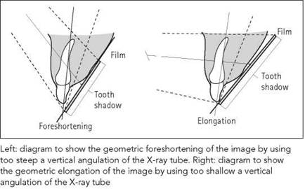
• Incorrect vertical angulation of the X-ray tube causes distortion of the image.
• Incorrect horizontal placement of the X-ray tube results in horizontal overlap of the contact points of the teeth, reducing the diagnostic yield for the clinician.
When using a bitewing film-holding beam-alignment instrument:
• Young children often find these devices uncomfortable.
• If the patient clinically exhibits periodontal bone loss of more than 6 mm, then two vertically positioned films (i.e. with the narrower length positioned parallel to the floor of the mouth) are required to enable the bone of the periodontium to be imaged (see section on specialized film holders, p. 288).
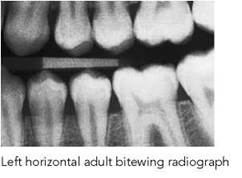


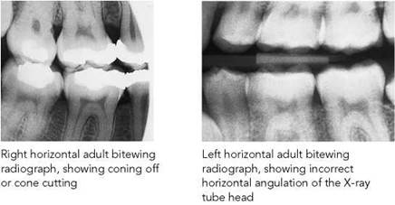
Note
Access to previous radiographs may reveal the need for vertical bitewings.
Bitewing radiography
Position of patient and film using a bitewing tab attached to the packet
• The correct film size is chosen and the bitewing tab is attached.
• The patient’s head must be supported adequately, with the medial plane vertical and the occlusal plane horizontal.
• Hold the tab between thumb and forefinger.
• Place the film in the lingual sulcus.
• The anterior edge of the film should be located opposite to the distal aspect of the lower canine.
• The tab rests on the occlusal surface of the lower teeth.
• The patient is told to bite gently on the tab and, when the teeth are almost in contact, the operator pulls the tab laterally to ensure that there is good contact between the film and the teeth.
• The operator releases their hold on the tab and concomitantly informs the patient to continue biting on the tab.
Direction and centring of the X-ray beam
• The tube is angled five to eight degrees downward (caudad) with the central ray at the level of the occlusal plane and perpendicular to the contact points of the teeth.
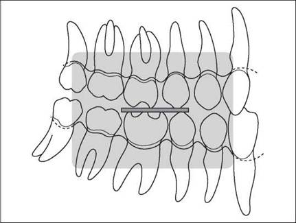
Diagram to show the correct position of the adult horizontal bitewing

Ideal position for a left adult horizontal bitewing using a bitewing tab

Positioning of the patient and the X-ray tube for a right bitewing radiograph using a bitewing tab
Position of patient and film using a bitewing film-holding/beam-alignment instrument
• The correct film size is chosen and placed in the film holder.
• The film holder is introduced into the mouth, rotated over the tongue and positioned in the lingual sulcus.
• The anterior edge of the film should be located opposite to the distal edge of the lower canine.
• The bite block rests on the occlusal surface of the lower teeth.
• The patient is told to bite gently on the bite block. At the same time, the operator ensures that there is good contact between the image receptor and the teeth.
• Ask the patient to continue biting on the bite block to position securely the film holder.
Direction and centring of the X-ray beam
• As directed by the extra-oral aiming device of the holder.
Quality standards for bitewing radiography
Evidence of optimal image geometry
• There should be no evidence of bending of the image of the teeth on the image.
• There should be no foreshortening or elongation of the teeth.
• Ideally, there should be no horizontal overlap.
If overlap is present, it should not obscure more than one-half the enamel thickness. This may be unavoidable due to anatomical factors (e.g. overcrowding, shape of dental arch), necessitating an additional bitewing or periapical radiograph.
Correct coverage
• The film should cover the distal surfaces of the canine teeth and the mesial surfaces of the most posterior erupted teeth.
• The periodontal bone level should be visible and imaged equally in the maxilla/mandible, confirming ideal centring.
Good density and contrast
There should be good density and adequate contrast between the enamel and the dentine.
Adequate number of films
When the third molars are erupted or partially erupted and impacted, and all the other teeth are present, two films may be needed on each side to evaluate the dentition.
Extreme curvature of the arch may impact on the number of films required.
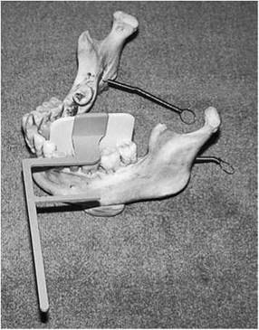
Lateral view of a Hawe-Neos Kwikbite film holder positioned for a left bitewing radiograph on a dried mandible
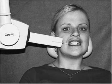
Positioning of the patient and the X-ray tube for a right bitewing radiograph using a Hawe-Neos Kwikbite film holder and rectangular collimation of the X-ray tube
Adequate processing and dark room techniques
• No pressure marks on film, no emulsion scratches.
• No roller marks (automatic processing only).
• No evidence of film fog.
• No chemical streaks/splashes/contamination.
• No evidence of inadequate fixation/washing.
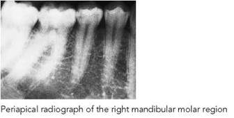

Periapical radiography provides an image of the teeth, the surrounding periodontal tissues and the alveolar bone.
There are many clinical indications for periapical radiography:
• Assessment of the periodontium encompassing the periapical and the periodontal status.
• Assessment of apical pathology and other lesions situated within alveolar bone.
• Pre- and postoperative assessment of alveolar surgery.
• Following trauma to teeth and alveolar bone.
• Localization of teeth and presence/absence of teeth.
• Before extraction to assess root morphology and the relationship of roots to vital structures, i.e. the inferior dental canal, the maxillary antrum.
• During endodontic therapy.
• Pre- and postoperative assessment of implants.
The two available techniques are:
• bisecting angle technique;
• paralleling technique.
Irrespective of the technique used, the front aspect (or imaging surface) of the film must be positioned facing the X-ray tube.
Bisecting angle technique
This technique is based upon the geometric theorem of isometry. It requires the central ray of the X-ray beam to pass through the root of the tooth at right-angles to a plane that is the bisector of the angle formed by the long axis of the tooth and the plane of the film.
With the bisecting angle technique, positioning is relatively simple but there are many variables in the technique.
Two methods are employed to stabilize the film intra-orally:
• the patient’s finger;
• a film-holding instrument.
The use of a film-holding instrument is preferred, as it reduces distortion due to film bending and stabilizes the film, ensuring better patient cooperation. However, the resulting X-ray may exhibit image shape distortion as a result of incorrect vertical angulation of the tube.
Bisecting angle technique (contd)
The convention for intra-oral film placement is as follows:
• Anterior teeth (incisors and canines): long axis of film vertical.
• Posterior teeth (premolars and molars): long axis of film horizontal.
Position of patient and film
• The patient's head must be supported adequately with the medial plane vertical and the occlusal plane horizontal (i.e. upper occlusal plane and lower occlusal plane for maxillary and mandibular radiography, respectively).
If a film holder is used:
• The correct film size is chosen and placed in the film holder.
• Position the film holder intra-orally adjacent to the lingual/palatal aspects of the tooth/teeth to be imaged.
• Insert a cotton-wool roll between the opposing teeth and the bite block.
• Ask the patient to close together slowly to allow gradual accommodation of the film holder intra-orally.
• Tell the patient to continue biting on the bite block to position the film holder securely.
If the patient's finger is used:
• The correct film size is chosen and positioned intra-orally.
• Ensure that the tooth/teeth being examined are in the middle of the film.
• 2 mm of the film packet should extend beyond the incisal or occlusal margin to ensure that the entire tooth is imaged.
• Instruct the patient to gently support the film using either their index finger or thumb.
• Apply the patient's finger/thumb solely to the area of film that overlies the crown and gingival tissues of the teeth. This reduces the possibility of distortion by bending of the film covering the root and periapical tissues.
Direction and centring of the X-ray beam
• The X-ray beam should be centred vertically on the midpoint of the tooth to be examined.
• Look at the tooth, the film, and the bisecting angle between the two. This achieves the correct vertical angulation of the tube.
• It is important to remember that proclined teeth will require more angulation, whilst retroclined teeth will need less angulation.
• The X-ray tube must be positioned so that the beam is at right-angles to the labial or buccal surfaces of the teeth to prevent horizontal overlap.
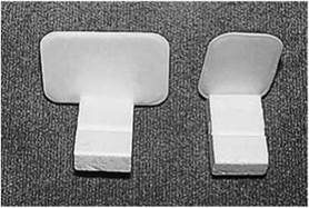
Rinn Greene Stabe® film holder with (from left to right) horizontal film placement for the premolars and molars and vertical film placement for the incisors and canines
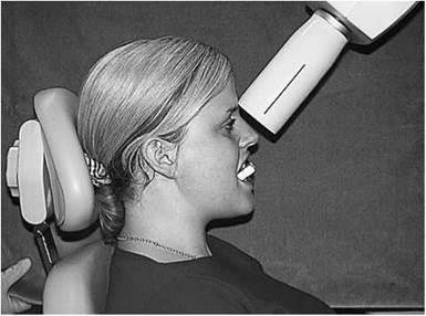
Positioning of the patient and the X-ray tube for a periapical radiograph of the maxillary incisors using the Rinn Greene Stabe® film holder
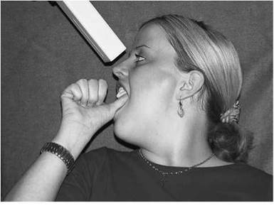
Positioning of the patient and the X-ray tube for a periapical radiograph of the maxillary incisors, using the thumb for support
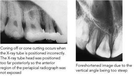
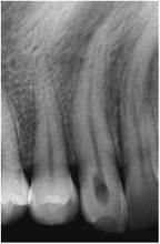
Excessive pressure when stabilizing the film or incorrect placement of the film in the mouth results in bending of the film packet during exposure
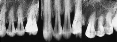
The effect of beam angulation on periodontal bone levels. A steep vertical angle (extreme right) masks bone loss, whilst too shallow an angle (centre) amplifies the extent of bone loss. The image on the extreme left of this dried skull series represents the correct geometry and accurate bone levels

Bisecting angle technique
Notes
• Correct positioning and angulation of the X-ray tube are needed to ensure adequate film coverage without evidence of coning off.
• Incorrect vertical angulation of the X-ray tube causes distortion of the image and may result in inaccuracies in diagnosis.
• The image can be distorted due to incorrect placement of film and/or the patient’s finger.
• Inaccurate vertical angulation of the X-ray tube results in misrepresentation of the alveolar bone levels.
• Incorrect horizontal placement of the X-ray tube results in horizontal overlap of the contact point of the teeth.
• The image of the zygomatic bone frequently overlies the roots of upper molars.
Imaging considerations
Conventionally, the technique uses a short tube-to-film distance and the object distance is reduced by close approximation of the film to the palatal or lingual aspect of the alveolar ridge.
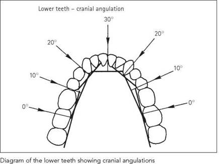
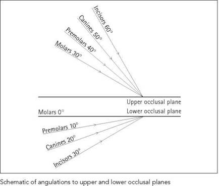
With the occlusal plane horizontal, the X-ray tube is positioned vertically by an assessment of the bisected plane for each individual patient. This technique is preferred to the use of the standardized vertical tube angulations (see tables on p. 298) as it allows for anatomical variations.
Bisecting angle technique (contd)
|
Angulations and centring points for the bisecting angle technique in the maxilla |
||
|
Region |
Centring point |
Vertical angulation (degrees) |
|
Incisor: central |
Midline through tip of nose |
50-60 (average 50) |
|
Incisor: lateral |
Ala of nose, 1 cm from midline |
50-60 (average 50) |
|
Canine Premolar |
Ala of nose On the cheek: at the point of intersection of a line down from the midpoint of the inner and outer canthus of the eye and the ala-tragus line |
45-50 35-40 |
|
Molar |
On the cheek: at the point of intersection of a line down from a point 1 cm posterior to the outer canthus of the eye and the ala-tragus line |
20-30 |
Angulations and centring points for the bisecting angle technique in the mandible (negative angle indicates upward (cephalad) angulation of the tube)
|
Region |
Centring point |
Vertical angulation (degrees) |
|
Incisors |
Midline, 1 cm above the lower border of the mandible |
-20 to -30 |
|
Canine |
Vertical line down from the outer aspect of the ala of nose, centring 1 cm above the lower border of the mandible |
-20 to -30 |
|
Premolar |
Vertical line down from the midpoint between the inner and outer canthus of the eye, centring 1 cm above the lower border of the mandible |
-10 to -15 |
|
Molar |
Vertical line down from a point 1 cm posterior to the outer canthus of the eye, centring 1 cm above the lower border of the mandible |
0 to -10 |
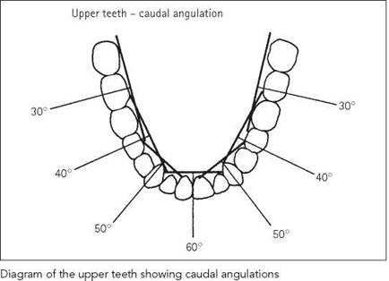
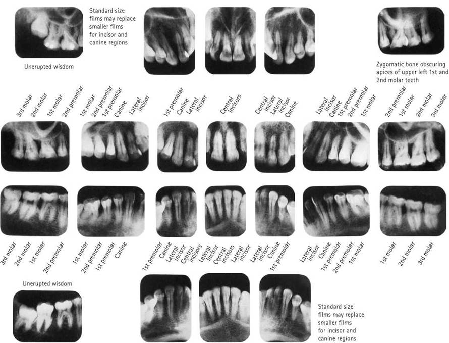
Examples of adult full mouth radiography (upper and lower jaw)
Paralleling technique
The paralleling technique requires that the X-ray film is positioned parallel with the long axes of the teeth. The central ray of the X-ray beam passes at right-angles, i.e. perpendicular, to the tooth.
In order to minimize magnification of the image and subsequent loss of image sharpness, the technique uses an increased focal spot-to-object distance, ensuring that a more parallel X-ray beam is incident to the object and image receptor.
Adopting the paralleling technique has many benefits for both the operator and the patient:
• Minimal elongation/foreshortening/distortion.
• Increased focus-to-skin distance (FSD) reduces surface dose.
• Increased FSD improves image quality by reducing the penumbra effect.
• Reduction in distortion effects due to bending of the film/image receptor.
Disadvantages of the paralleling technique include:
• The paralleling technique can be used when using X-ray equipment with a short FFD (less than 20 cm) providing the operator accepts increased magnification.
• Anatomical limitations, such as a shallow palate, principally in the maxillary molar and anterior regions, preclude true parallel placement of the film relative to the tooth.
Radiological considerations
• The use of the paralleling technique along with film-holding beam-alignment instruments allows the operator to obtain images that have reproducibility and standardization. This allows the clinician to study longitudinal disease progression and to assess accurately treatment outcomes.
• Provided the film position does not diverge from the long axis (or axes) of the tooth by more than 20 degrees, the image will demonstrate no evidence of longitudinal distortion.
• In endodontic treatment, it may be necessary to separate superimposed root canals using two radiographs at different horizontal angles. Obtain one ‘normal’ film and one with a 20-degree oblique horizontal beam angle for all molars and maxillary first premolars.
• Assessment of some horizontally impacted mandibular third molars may require two films to image the apex. Obtain one ‘normal’ film and one with a more posterior 20-degree oblique horizontal beam angle.


The Rinn XCP® film holder: from left to right the anterior and posterior devices with size 0 and size 2 films respectively
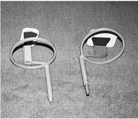
The Hawe-Neos Super Bite® film holder: from left to right the anterior and posterior devices with size 0 and size 2 films respectively
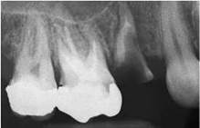
A posterior periapical of the right maxilla taken using the paralleling technique
Paralleling technique
Film-holding beam-alignment instruments
Most devices require the use of different sized films in the anterior and posterior regions of the oral cavity. The usual convention for film use is:
• Anterior teeth (incisors and canines): size 0 (or size 1) film with long axis of film vertical. The alternative use of a size 1 film is governed solely by operator preference.
• Posterior teeth (premolars and molars): size 2 film (31 X 41 mm) with long axis of film horizontal.
• Some operators use size 0 (or size 1) for premolars.
• Adopting these techniques limits longitudinal distortion and ensures patient comfort.
Essential image characteristics
• There should be no evidence of bending of the teeth and the periapical region of interest on the image.
• There should be no foreshortening or elongation of the teeth.
• Ideally, there should be no horizontal overlap. If overlap is present, then it must not obscure the pulp/root canals.
• The film should demonstrate all the tooth/teeth of interest (i.e. crown and root(s)).
• There should be 3 mm of periapical bone visible to enable an assessment of apical anatomy.
• There should be good density and adequate contrast between the enamel and dentine.
• There should be no pressure marks on the film and no emulsion scratches.
• There should be no roller marks (automatic processing only).
• There should be no evidence of film fog.
• There should be no chemical streaks/splashes/contamination.
• There should be no evidence of inadequate fixation/washing.
Paralleling technique (contd)
Position of patient and film
• The appropriate film holder and periapical film are selected and assembled.
• Place the bite block in contact with the edge of the tooth to be imaged. Ensure that the film covers the particular tooth/teeth to be examined.
• Maxilla:
- For the incisor, canine, premolar and molar regions, the film holder must be positioned some distance from the tooth to achieve parallelism. This requires using the entire horizontal length of the bite block with the film holder occupying the highest part of the palate.
• Mandible:
- For the lower incisor teeth, position the film holder in the plane of an imaginary line intersecting the first mandibular premolars or as posterior as anatomy will allow.
- For the mandibular premolars and molars, position the film holder in the lingual sulcus adjacent to the teeth selected for imaging.
• Insert a cotton-wool roll between the opposing teeth and the bite block.
• Ask the patient to close together slowly to allow gradual accommodation of the film holder intra-orally.
• As the patient closes together, rotate the bite block in an upward/downward direction (as appropriate).
• Instruct the patient to close firmly on the bite block and to continue biting until the examination is completed.
• Slide the aiming ring down the indicator rod to approximate the skin surface.
Direction and centring of the X-ray beam
• Correctly align the X-ray tube adjacent to the indicator rod and aimin a rino in notn vortical and nori'zontal nlanoç

Diagram showing the correct position of the film in the film holder bite block relative to an anterior tooth in the maxilla

Diagram showing the incorrect position of the film in the film holder bite block. When the holder is positioned adjacent to the tooth (mimicking the set-up for the bisecting technique), true parallelism cannot be achieved and the holder is extremely uncomfortable for the patient
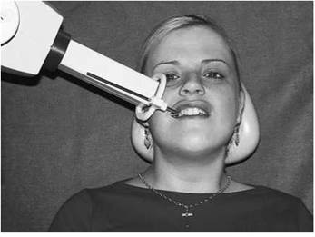
Positioning of the patient and the X-ray tube for a periapical radiograph of the maxillary molar region using the Rinn XCP® posterior film holder
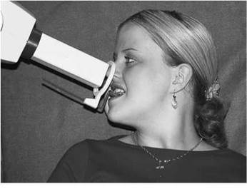
Positioning of the patient and the X-ray tube for a periapical radiograph of the maxillary central incisors using the Rinn XCP® anterior film holder
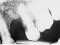
Radiograph of the upper left maxilla shows the bite block being trapped against the upper left canine due to the adjacent edentulous region. This has the effect of 'propping' open the bite

Use of cotton wool rolls to stabilize the bite block in an edentulous area

Loss of apices due to lack of continuous biting pressure
Paralleling technique
Common faults and remedies
• Care must be taken in the partially dentate patient, as edentulous areas can displace the holder and prop open the bite.
• Cotton wool rolls used as a support in the edentulous area often overcome the problem.
• Ensure that the patient understands that they must continue to bite on the bite block. Failure to do this results in loss of apices from the resultant image.
• In edentulous patients, the bisecting technique is preferred.
Third molar region
Positioning of the film using conventional film holders can be uncomfortable for the patient in the third molar region. To overcome these problems, the following techniques should be adopted:
Imaging mandibular third molars
Surgical haemostats/needle holders can be used to stabilize the film. One beak of the device is modified into a bite block by soldering a semi-circular stainless wire on to the needle holder and covering it with heavy-duty autoclavable plastic. This simple addition significantly reduces the problem of the patient inadvertently moving the holder.
Position of patient and film
• The upper leading anterior edge of a size 2 film is attached securely to the beaks of the needle holder, ensuring that the front aspect (or imaging surface) will face the X-ray tube when positioned intra-orally.
• The film is positioned in the lingual sulcus as far posteriorly as possible.
• The patient is instructed to bring their teeth together slowly. This has the effect of lowering of the floor of the mouth, thereby providing more space to accommodate the film.
• Simultaneously, the operator positions the film holder so that the leading edge of the film lies adjacent to the mesial aspect of the mandibular first molar. It is important to do this gradually to reduce discomfort for the patient.
• The patient is instructed to hold the handles of the needle holder.
Direction and centring of the X-ray beam
• The tube is centred and angulated as outlined in the table on p. 298 for the mandibular molar region.
• The X-ray tube must be positioned so that the beam is at right-angles to the labial or buccal surfaces of the teeth to prevent horizontal overlap, and the film is exposed.
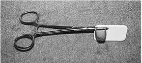
Modified surgical haemostats with soldered bite block
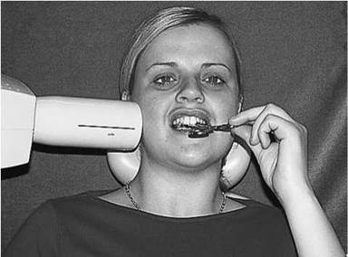
Positioning of the patient and the X-ray tube for a periapical radiograph of the mandibular third molar. The holder is stabilized by the patient's hand

Periapical radiograph of the lower left third molar showing a complex root form and close approximation of root apices to the mandibular canal
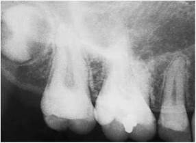
Periapical of the right molar region showing a developing third maxillary molar

Periapical of the left molar region showing normal anatomy of the tuberosity, the antral floor and the inferior aspect of the zygoma
Third molar region
Imaging maxillary third molars
The use of a film holder in this region is dependent on the patient's ability to tolerate the device. If the use of a film holder is impossible, then the bisecting angle technique is adopted.
Position of patient and film
• The patient's head must be supported adequately with the medial plane vertical and the maxillary occlusal plane horizontal.
• Position the film intra-orally so that the front aspect (or imaging surface) will face the X-ray tube.
• The film is positioned far enough posteriorly to cover the third molar region, with the anterior border just covering the second premolar.
• The film is supported by the patient's index finger or thumb. It is positioned with 2 mm of film packet extending beyond the occlusal plane to ensure that the entire tooth is imaged. The image plane must be flat to reduce the distortion effects of bending.
Direction and centring of the X-ray beam
• The X-ray tube is centred and angulated as outlined in the table on p. 298 for the maxillary molar region.
• The X-ray tube must be positioned so that the beam is at right-angles to the labial or buccal surfaces of the teeth to prevent horizontal overlap, and the film is exposed.
Complete mouth survey or full mouth survey
The complete mouth survey or full mouth survey is composed of a series of individual periapical films covering all the teeth and the tooth-bearing alveolar bone of the dental arches. Most patients require 14 periapical films to fulfil these requirements. Careful technique is essential to reduce the need for repeat examinations.
Occlusal radiography
Occlusal projections are used to image relatively large areas of the dental arches. Their main uses are as follows:
• To localize accurately unerupted teeth, supernumeraries, retained roots, odontomes, foreign bodies, radio-opaque salivary calculi, etc. in regions of the oral cavity where the occlusal view provides a plan view of the jaw.
• To localize accurately unerupted teeth, supernumeraries, retained roots, odontomes and foreign bodies using parallax when combined with another film of the region taken using a different vertical angulation.
• To evaluate a patient with severe trismus or who cannot tolerate periapical radiography.
• To evaluate patients in cases of trauma, when information is required on the extent and location of fractures to the teeth and the maxillary and mandibular bones.
• To evaluate the medial-lateral extent of pathology, e.g. cysts, tumours, malignancy, osteodystrophies.
Terminology
There is a diversity of terminology used to describe the various types of occlusal projections. The terminology used reflects beam angulation or the anatomical region in which the tube is positioned.
In this section, alternative but synonymous nomenclature appears in brackets to ensure a common understanding amongst the wider readership of the text.
Recommended projections
The occlusal projections that are necessary for full examination of the dental arches can be seen below. These are presented as true and oblique projections.
Radiological considerations
The clinician should ensure that their request for certain occlusal projections (i.e. true occlusal) should indicate the tooth over which the beam is centred.
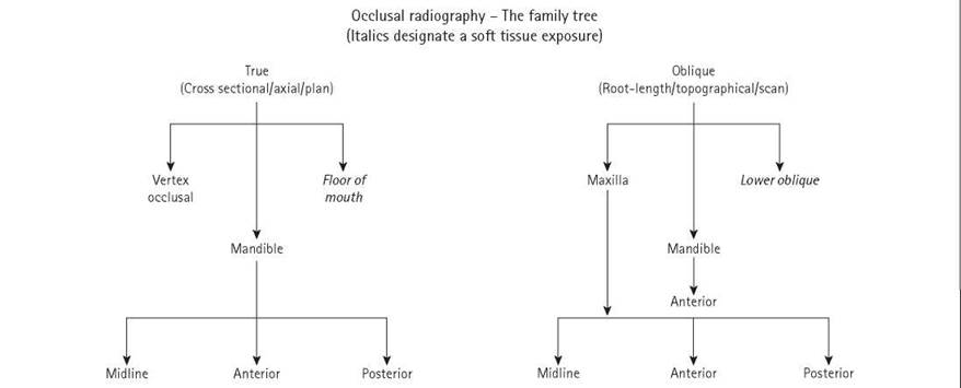
Occlusal radiography - the family tree

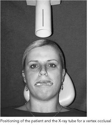
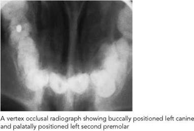
Vertex occlusal of the maxilla
This projection shows a plan view of the maxillary teeth and is used to demonstrate the bucco-palatal relationship of unerupted teeth in the dental arch.
The vertex occlusal is a projection that is requested infrequently now. Because of the density of tissue through which the beam must pass, it requires the use of an intra-oral cassette with rare-earth intensifying screens to reduce the dose to the patient. If these screens are not available routinely, then existing rare-earth screens can easily be cut down to size to fit the intra-oral cassette.
The loaded cassette, pre-labelled with a lead letter to designate the side, is placed inside a small plastic bag to prevent salivary contamination. Statutory requirements require the use of a lead apron for this projection [see Radiation protection, p. 290).
Position of patient and cassette
• The patient sits comfortably, with the head supported. The median plane is vertical and the occlusal plane is horizontal.
• The occlusal cassette is positioned with its long axis anteroposteriorly (i.e. parallel to the median plane) within the oral cavity.
• The cassette should be placed flat in the patient's mouth, adjacent to the occlusal surface of the lower teeth.
• Position the cassette as far back as possible, at least to the level of the first permanent molars.
• The patient should bite together gently to stabilize the cassette intra-orally.
Direction and centring of the X-ray beam
• The tube is positioned over the vertex of the skull, and the central ray is directed along the median plane downward (caudad) through the long axis of the upper central incisor teeth.
Note
It is important to remember that the beam is not at right-angles to the occlusal plane.
True occlusal of the mandible
Synonyms: submental occlusal, lower true occlusal, occlusal plan view of the lower jaw, cross-sectional mandibular occlusal projection.
Midline
This projection shows a plan view of the mandible, with the teeth and the lingual and buccal cortices seen in cross-section.
Position of patient and film
• The occlusal film should be placed as far back in the mouth as the patient will tolerate, with the film resting on the occlusal surfaces of the lower teeth. The tube side of the film faces the floor of the mouth with the long axis of film extending across the oral cavity (i.e. perpendicular to the sagittal plane).
• The anterior leading edge of the film should extend 1 cm beyond the labial aspects of the mandible incisor teeth.
• The patient is instructed to extend their head backwards so that the ala-tragus line is almost perpendicular to the floor. The head is then supported adequately in this position.
• The patient should bite together gently to avoid pressure marks on the film.
Direction and centring of the X-ray beam
• The tube is placed well down below the patient's chin and directed vertically at 90 degrees to the occlusal plane and the film.
• Centre the tube in the midline at 90 degrees to an imaginary line joining the first permanent molars (i.e. =3 cm distal to the midline of the chin).
Anterior
This projection is designed to image the anterior regions of the mandible.
The only modification to the technique described for the midline true occlusal is that the tube is centred on the symphysis menti, with the beam positioned so that the central ray passes through the root canals of the lower central incisors.
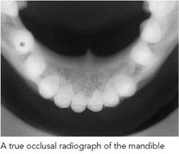
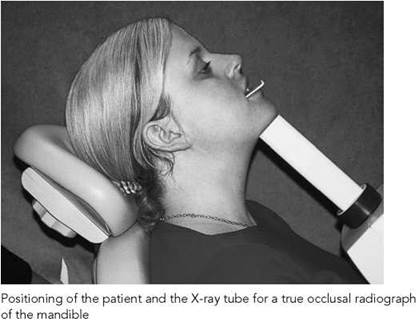

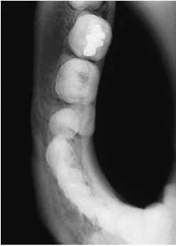
Posterior true occlusal radiograph of right mandible

Posterior true occlusal radiograph of the left mandible. A cystic lesion is apparent in the premolar region

True occlusal (with soft tissue exposure) showing a discrete salivary calculus in the midline, adjacent to the left submandibular duct orifice
True occlusal of the mandible
Posterior
If pathology is related to only one side of the mandible, then the posterior view is used.
To achieve this projection, some modifications of the technique outlined for the midline true occlusal are needed:
• The film is positioned with its long axis antero-posteriorly (i.e. parallel with the sagittal plane) on the side of interest.
• The lateral aspect of the film extends = 1 cm buccally to the dental arch but remains parallel to the buccal surfaces of the posterior teeth.
• The tube is centred below the body of the mandible on the side of interest (=3 cm distal to the antero-lateral aspect of the chin) at 90 degrees to the film.
Floor of mouth
This projection is performed to image radio-opaque calculi in the anterior aspect of the floor of the mouth and to identify effectively fragments of fractured tooth and radio-opaque foreign bodies embedded within the lower lip.
• Positioning of the patient, along with film and tube placement, are identical to those described previously for the midline true occlusal.
• Exposure is reduced by a factor of =50% to that used to produce an image of the teeth and mandible.
Radiological considerations
More than one-third (35%) of submandibular calculi are found at the hilum of the gland. While the true occlusal of the mandible (see p. 308 opposite) images the anterior aspects of the submandibular duct adequately, the posterior portion is obscured by the image of the lingual cortex of the mandible. The posterior oblique occlusal (see p. 313) overcomes the problem.
Notes
Other radiographic projections are available to image calculi in this region, including true lateral with floor of mouth depressed and panoramic view.
Oblique occlusal of the maxilla
Midline occlusal
Synonyms: upper standard occlusal, standard occlusal, 70-degree maxillary occlusal.
The projection is used to show the anterior maxilla.
Position of patient and film
• The patient sits comfortably with the head supported. The median plane is vertical and the occlusal plane is horizontal.
• An occlusal film is placed flat in the patient's mouth, resting on the occlusal surfaces of the lower teeth, with the tube side of the film facing the vault of the palate.
• The convention for positioning the film in the mouth is:
- Adults: long axis of film extending across the oral cavity (i.e. perpendicular to the sagittal plane).
- Children: long axis of film positioned antero-posteriorly in the oral cavity (i.e. parallel to the sagittal plane). NB: in younger children with small mouths, a periapical film can be substituted effectively.
• The anterior leading edge of the film should extend 1 cm beyond the labial aspects of the maxillary incisor teeth.
• The film should be placed as far back as the patient will tolerate.
• The patient should bite together gently to avoid pressure marks on the film.
Direction and centring of the X-ray beam
• The tube is positioned above the patient in the midline and angled downwards (caudad) at 65-70 degrees, the central ray passing through the bridge of the nose towards the centre of the film.
Modifications of the technique
Using a soft-tissue exposure, this projection is effective in identifying fragments of tooth and/or radio-opaque foreign bodies within the upper lip following trauma.
Another useful projection to identify radio-opaque structures embedded within the lips is the true lateral. The patient holds the occlusal film parallel to the sagittal plane using the thumb to support the lower edge and the fingers to stabilize the film against the cheek.
This projection is taken using soft-tissue settings. Unless the object is confirmed clinically to be solitary and situated in the midline, then the true lateral must be supplemented by other projections (i.e. at right-angles to it) to enable accurate localization.
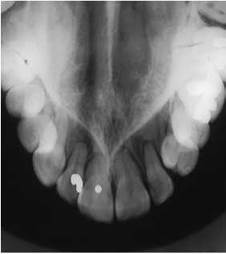
Upper standard oblique occlusal radiograph

Positioning of the patient and the X-ray tube (from the side) for an upper standard oblique occlusal radiograph
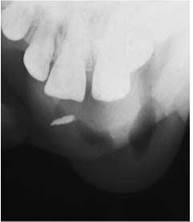
Upper standard oblique occlusal radiograph (with soft tissue exposure) showing fractured tooth fragment localized to soft tissues of upper lip

True lateral projection of the case illustrated above. Embedded tooth fragment is clearly seen
Oblique occlusal of the maxilla
Anterior oblique occlusal
This projection is used to image the anterior region of the maxilla. The tube is centred over the lateral/canine region and is commonly used combined with a periapical film of this region to assist in localization of supernumerary teeth, unerupted canines, etc.
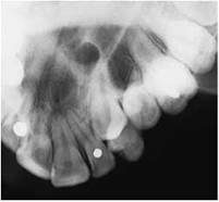
Anterior oblique occlusal of the left maxilla showing an unerupted left canine
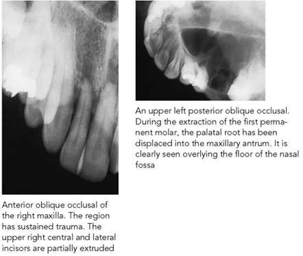
Position of patient and film
• Positioning is identical to the standard, except that film coverage is restricted to the anterior region of interest.
Direction and centring of the X-ray beam
• The centring point is the bridge of the nose with downward (caudal) angulation of 60 degrees.
Posterior oblique occlusal
Synonyms: upper oblique occlusal, oblique maxillary occlusal, oblique occlusal of the upper jaw, lateral maxillary occlusal projection.
This projection demonstrates the posterior quadrant of the maxillary arch, the teeth, the alveolar bone and part of the maxillary antrum, the floor of the antrum and the zygomatic process of the maxilla superimposed over the roots and crowns of the molar teeth.
Position of patient and film
• The patient sits comfortably, with the head supported. The median plane is vertical and the occlusal plane is horizontal.
• An occlusal film is placed flat in the patient’s mouth on the side of interest.
• The film lies on the occlusal surfaces of the lower teeth, with the tube side of the film facing the vault of the palate. The convention for positioning the film is that the long axis of the film lies antero-posteriorly in the oral cavity (i.e. parallel to the median plane).
• The edge of the film adjacent to the cheek should extend 1 cm lateral to the buccal surfaces of the posterior teeth to be imaged.
• It should be positioned as far back as the patient will tolerate.
• The patient should bite together gently to avoid pressure marks on the film.
Direction and centring of the X-ray beam
• The X-ray tube is positioned towards the side of the face where pathology is suspected and angled downwards (cau- dad) at 65-70 degrees through the cheek.
• The centring point is medial to the outer canthus of the eye but level with the pupil. It is important to ensure that the central ray is at right-angles to the dental arch.
Notes
• It is important not to position the tube more laterally than the centring point outlined above, otherwise the body of the zygoma will obscure important detail in the area of interest.
• This is a technically demanding view when using rectangular collimation.
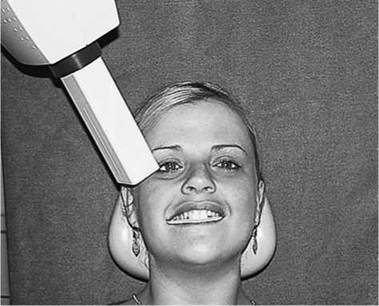
Positioning of the patient and the X-ray tube for the right upper posterior oblique occlusal
Oblique occlusal of the mandible
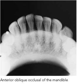
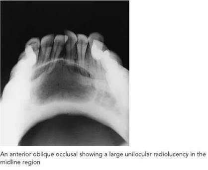
Anterior oblique occlusal
Synonyms: lower anterior occlusal, lower midline oblique occlusal, oblique mandibular occlusal, anterior mandibular occlusal projection.
This projection shows the anterior teeth and the inferior cortical border.
Position of patient and film
• The patient sits comfortably, with the head supported. The median plane is vertical.
• An occlusal film is placed flat in the patient's mouth, resting on the occlusal surfaces of the lower teeth. The film should be placed with the tube side of the film facing the floor of the mouth.
• The long axis of film is positioned so that it extends across the oral cavity (i.e. perpendicular to the sagittal plane).
• The anterior leading edge of the film should extend 1 cm beyond the labial aspects of the mandibular incisor teeth.
• The patient should bite together gently to avoid pressure marks on the film.
• The patient is instructed to extend their head backwards so that the occlusal plane is 35 degrees to the horizontal. This allows the tube to be more easily positioned adjacent to the chin. The head is supported adequately in this position.
Direction and centring of the X-ray beam
• The tube is positioned in the midline achieving an upward angle of ten degrees (i.e. an overall upward angulation of 45 degrees) to the plane of the film, centring through the midpoint of the chin.

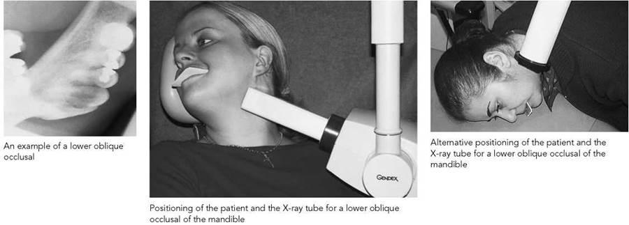
Lower oblique occlusal
Synonym: oblique occlusal.
This projection demonstrates the soft tissues of the middle and posterior aspects of the floor of the mouth.
Position of patient and film
• The patient sits comfortably, with the head supported. The median plane is vertical and the occlusal plane is horizontal.
• An occlusal film is placed flat in the patient’s mouth on the side of interest.
• The film lies on the occlusal surfaces of the lower teeth, with the tube side of the film facing the floor of the mouth. The convention for positioning the film is that the long axis of film lies antero-posteriorly in the oral cavity (i.e. parallel with the sagittal plane).
• The edge of the film adjacent to the cheek should extend 1 cm lateral to the buccal surfaces of the posterior teeth to be imaged.
• The film must be positioned as far back as the patient will tolerate and the patient should bite together gently to avoid pressure marks on the film.
• The operator then supports the patient’s head and rotates it away from the side of interest and, simultaneously, elevates the chin.
• This rotation and elevation allows the X-ray tube to be positioned below the angle of the mandible.
Oblique occlusal of the mandible
Direction and centring of the X-ray beam
• The X-ray tube is positioned 2 cm below and behind the angle of the mandible.
• The centring point is the angle of the mandible with an upward angle (cephalad) to the plane of the film of 115 degrees.
• It is important to ensure that the beam is parallel to the lingual plate of the mandible.
Alternative technique
Elderly or short-necked patients can be difficult to image with this technique, but an effective modification has been devised (Semple and Gibb, 1982):
• The patient is seated adjacent to a flat surface (i.e. table or work surface). With the film positioned intra-orally, the head is tipped over so that the forehead and nose are in contact with the table, and the head is rotated with the affected side 20 degrees away from the table.
• The X-ray tube is positioned above and behind the patient’s shoulder. Use identical centring points as detailed above, with the tube position 25 degrees from the vertical.
Modifications of the technique
Using a soft-tissue exposure, this projection is employed primarily to detect radio-opaque calculi in the proximal regions of the submandibular duct as it crosses the free edge of the mylohyoid muscle. This modification is also referred to as the posterior oblique occlusal and postero-anterior lower occlusal.
Lateral oblique of the mandible and maxilla
The lateral oblique radiograph is an extra-oral projection produced using conventional intra-oral X-ray equipment that reveals a larger area of the jaws than intra-oral radiography. It can also be produced using a skull unit.
Despite the growth of panoramic radiography, lateral oblique radiography remains a valid technique.
Although intra-oral radiography remains the obvious imaging modality for the majority of dental patients, there will be a relatively small number of dental/oral conditions that, because of their size and/or location, cannot be adequately imaged using intra-oral techniques. These are outlined as follows:
• Assessment of the presence/absence of teeth and also the position of unerupted teeth (especially third molars).
• Detection and assessment of fractures of the mandible.
• Assessment of large pathological lesions (e.g. cysts, tumours, osteodystrophies).
• When intra-oral radiography is impossible (e.g. trismus, severe gagging).
• Patients with physical and/or medical conditions in which large coverage and a rapid imaging technique is needed.
As a variety of different lateral oblique projections are carried out, the exact positioning of each of these views depends on the area or region of the jaws under examination.
This section will confine itself to describing the two most commonly requested lateral oblique projections:
• A lateral oblique projection imaging the body of the mandible and the maxilla.
• A lateral oblique projection imaging the ascending ramus of the mandible.
Radiographers requiring a fuller description of the range of oblique lateral projections are referred to the specialist textbooks on dental radiography listed at the end of this chapter.
General imaging principles
• The head is rotated to ensure that the area under examination is parallel to the film.
• The film and the median plane are not parallel.
• To avoid superimposition of the opposite side of the jaws, the combined angulation of the angle between the median plane and the film plus the angulation of the X-ray beam must not be less than 20 degrees.
• The central ray is perpendicular to the film but oblique to the median plane.
Lateral oblique of the body of the mandible and maxilla
This projection shows the dentition in the premolar/molar region of the maxilla and mandible, the inferior cortex of the mandible, and the angle and ascending ramus of the mandible.
Position of patient and cassette
• The patient sits comfortably, with the head supported. The median plane is vertical.
• A 13 X 18-cm cassette is used with a removable film marker attached to designate the side of the mandible to be imaged.
• The cassette is positioned against the patient’s cheek overlying the region of the mandible under investigation, with the lower border parallel to the inferior border of the mandible but lying at least 2 cm below it.
• The positioning achieves a 10-degree angle of separation between the median sagittal plane and the film.
• The patient is instructed to stabilize the cassette in this position.
• The patient’s head is rotated to the side of interest. This positions the contralateral ascending ramus forwards and increases the area between the neck and the shoulder to provide space for the X-ray tube.
• The chin is raised slightly to increase the space between the posterior aspect of the mandible and the cervical spine.
• The patient is asked to protrude the mandible.
Direction and centring of the X-ray beam
• Direct the central ray at a point 2 cm below and behind the angle of the contralateral side of the mandible (see figure).
• Positioning of the tube is dependent upon the area of clinical interest, i.e.:
- third molar region for assessment of the position of third molars and possible pathology in this region;
- premolar region for assessment of the developing dentition;
- lower canine region if there is evidence of mandibular fracture or other pathology.
• The choice of beam angulation varies between 10 degrees upward and 10 degrees downward (see p. 315).
• The central ray is perpendicular to the plane of the film.
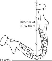
Schematic to illustrate the direction of the beam for a lateral oblique radiograph of the body of the mandible and maxilla
Lateral oblique of the body of the mandible and maxilla
Modification of the projection
• The choice of a downward beam angulation is related to the (clinical) need to avoid superimposition of the hyoid bone on the body of the mandible.
• To image the maxillary and mandibular canine/incisor region requires further rotation of the head to a point where the patient's nose is flattened against the cassette.
• It is important to ensure that the area of interest is parallel to the film. This technique reduces the angle of separation between the median sagittal plane and the film to five degrees.
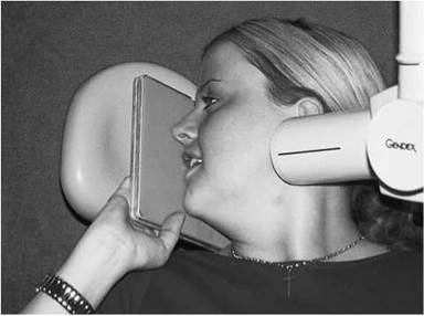
Cassette and the X-ray tube positions for a right lateral oblique radiograph of the body of the mandible and maxilla. Note the rotation of the head with flattening of the nose against the cassette
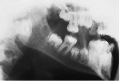
Lateral oblique radiograph of the body of the mandible and maxilla of a child in the mixed dentition
Lateral oblique of the ramus of the mandible
This projection gives an image of the ramus from the angle of the mandible to the condyle.
Position of patient and cassette
• The patient sits comfortably, with the head supported. The median plane is vertical.
• A 13 X 18-cm cassette is used with a removable film marker attached to designate the side of the mandible to be imaged.
• The cassette is positioned against the patient’s cheek overlying the ascending ramus and the posterior aspect of the condyle of the mandible under investigation.
• The cassette is positioned so that its lower border is parallel with the inferior border of the mandible but lies at least 2 cm below it.
• The positioning achieves a 10-degree angle of separation between the median sagittal plane and the film.
• The patient is instructed to support the cassette in this position.
• The mandible is extended as far as possible.
• Limit rotation of head (= 10 degrees) towards the cassette.
Direction and centring of the X-ray beam
• The central ray is directed posteriorly with upward angulation (cephalad) of 10 degrees towards the centre of the ramus of the mandible on the side of interest.
• The centring position of the tube is the contralateral side of the mandible at a point 2 cm below the inferior border in the region of the first/second permanent molar.
Note
Some operators prefer a slight (= 10 degrees) downward (cau- dad) angulation of the tube to prevent the image of the hyoid bone being superimposed on the body of the mandible.
Essential image characteristics
• There should be no removable metallic foreign bodies.
• There should be no motion artefacts.
• There should be no antero-posterior positioning errors.
• There should be no evidence of excessive elongation.
• There should be no evidence of incorrect horizontal angulation.
• There should be minimal superimposition of the hyoid bone on the region of (clinical) interest.
• There should be good density and adequate contrast between the enamel and the dentine.
• There should be no pressure marks on the film and no emulsion scratches.
• There should be no roller marks (automatic processing only).
• There should be no evidence of film fog.
• There should be no chemical streaks/splashes/contamination.
• There should be no evidence of inadequate fixation/washing.
• The name/date/left or right marker should be legible.

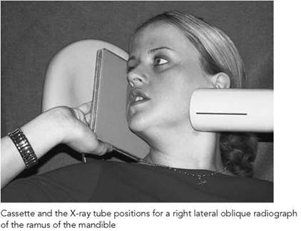
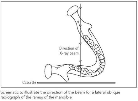
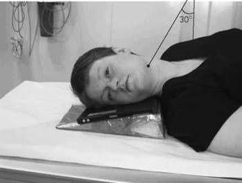
Patient lying supine on the X-ray couch and positioned for a right lateral oblique
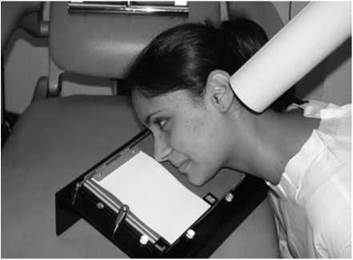
Patient positioned on an angle board for a right lateral oblique
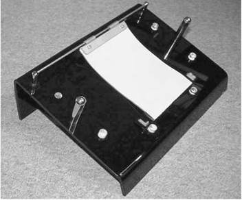
An angle board
Lateral oblique of the ramus of the mandible
Modification of the projection - patient supine
In a general department, the most convenient method of achieving the lateral oblique projection is with the patient supine on the X-ray couch.
Position of patient and cassette
• Use a 10-degree wedge-shaped foam pad to achieve separation of one side of the mandible from the other.
• Attach a removable film marker to the cassette to designate the side of the mandible to be imaged.
• With the cassette on the pad, the patient's head is rotated so the side of the jaw to be examined is parallel to the film, with the median sagittal plane parallel to the cassette.
• The head is tilted back on the spine to achieve further extension of the contralateral mandible away from the region of interest.
Direction and centring of the X-ray beam
• The central ray is angled 30 degrees cranially at an angle of 60 degrees to the cassette and is centred 5 cm inferior to the angle of the mandible remote from the cassette.
Using an angle board
An angle board is a device incorporating an incline to help separate the sides of the mandible.
Position of patient and cassette
• The head is positioned parallel to the angle board and cassette, but with the sagittal plane inclined to the vertical by the degree of angulation set by the device.
• Some angle boards incorporate ear rods to ensure accurate localization of the patient.
• A small forward tilt of the chin avoids superimposition of the cervical vertebrae on the ramus.
Direction and centring of the X-ray beam
• The tube is positioned below the angle of the mandible, remote from the film, and the central ray is directed towards the vertex.
• To avoid superimposition of the opposite side of the face, there must be an effective separation of 20 degrees.
• For example, with a sagittal plane angled at 15 degrees by the angle board, the central ray must be angled five degrees to the vertex to achieve the required separation of 20 degrees.
Bimolar projection
This technique is used in orthodontic practice. It shows both left and right oblique lateral views on one film. The technique incorporates a hinged lead shield to prevent exposure of the other side of the film.
Dental panoramic tomography
Synonyms: rotational panoramic radiography, orthopantomography (OPT), dental panoramic tomography (DPT), panoral.
Dental panoramic radiography is an extra-oral radiographic technique that produces an image of both jaws and their respective dentitions on a single film.
Panoramic radiography has supplanted lateral oblique radiography in that it is most useful in those patients who require an imaging modality providing a wide coverage of the jaws, such as:
• orthodontic assessment of the presence/absence of teeth;
• detection and assessment of fractures of the mandible;
• assessment of large pathological lesions (e.g. cysts, tumours, osteodystrophies);
• when intra-oral radiography is impossible (e.g. trismus, severe gagging);
• assessment of third molars before surgical removal.
Principles of panoramic image formation
Panoramic equipment is based upon a simultaneous rotational movement of the tube head and film cassette/carriage in equal but opposite directions around the patient’s head, which remains stationary. The technique employs a slit-collimated vertical X-ray beam, with an eight-degree upward inclination, in association with a similar collimation slit in front of the film cassette/carriage to receive the image.
Improvements in image production have centred upon refining the rotational movement and determining the ‘correct’ form of the image layer. Manufacturers vary in the methods employed to produce the panoramic image. However, irrespective of the type of rotational movement involved, the result is the production of an elliptical image layer with three-dimensional form (i.e. height and width) in the shape of the dental arch. This image layer is referred to as the focal trough.
Within the different types of panoramic equipment, there are noticeable variations in the width of this image layer. This variability is much more apparent in equipment employing a continuous moving rotational centre, resulting in a narrow anterior layer compared with the lateral aspects of the focal trough.

A dental panoramic tomograph of an adult dentate patient
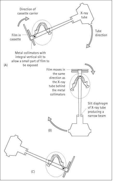
The schematic illustrates the relative positions and movement of the X-ray tubehead, cassette carrier and film during three stages of the exposure cycle of a continuous mode panoramic unit. The stages shown are: A, start of the exposure; B, intermediate stage of panoramic exposure; C, end of exposure. Throughout the exposure, a different part of the film is exposed as illustrated

The focal trough

Patient position too close to the film with very obvious reduction in the width of the anterior teeth. The patient is also wearing earrings (of different design) and their ghost shadow appears at a higher level on the contralateral side of the image
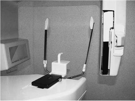
Patient-positioning devices on the Planmeca PM2002® panoramic unit: bite-peg, chin and temporal supports
Image acquisition
There are a number of factors inherent to panoramic radiography that reduce the diagnostic quality of the final image. These factors are:
• magnification variation;
• tomographic blur;
• overlap of adjacent teeth;
• superimposition of soft tissue and secondary shadows;
• limitations of resolution imposed by the image receptor, exposure parameters and processing conditions.
Magnification variation
While all types of radiographic projections exhibit a degree of magnification, the type associated with panoramic radiography is more complex. The individualized movement patterns, variations in the width of the beam, differing focus/object/film relationships, and the position/shape of the image layer chosen by the manufacturer can produce variations in magnification ranging from 10 to 30% between units.
Horizontal and vertical magnifications are only equal for structures at the centre of the focal plane. Within panoramic images, the degree of horizontal magnification varies considerably, depending upon the relationship of the structure to the image layer. Objects lying closer to the X-ray source (i.e. situated inside the focal trough) will display a greater degree of horizontal magnification. The situation is the reverse for those objects lying closer to the cassette (i.e. objects outside the focal trough), as they will be imaged with a relatively diminished horizontal magnification while the vertical shape remains virtually the same. This variability in horizontal shape is apparent by examining the appearance of anatomical structures within the focal trough (the tongue, hyoid bone) and those outside it (the zygomatic arch).
Minor inaccuracies in the antero-posterior positioning of the patient can easily lead to discrepancies between the vertical and horizontal magnification of teeth, with consequent distortions of tooth shape. These errors are most marked in the anterior regions of the jaws, where the focal plane is narrower.
Correct patient positioning is therefore essential for good image production. To achieve this, panoramic equipment employs various positioning aids to assist the operator. These include a system of light localizers (light beams diaphragm) to correctly position the patient, along with combinations of some or all of the following: chin rest, bite block, and two or more head supports.
Image acquisition (contd)
Tomographic blur
Panoramic radiography is known as a modified form of tomography, but only when tomography is described in the most general terms as a 'layer-forming imaging system'. The majority of panoramic systems have only one pre-designated rotational movement, resulting in one fixed form of image layer. The parameters of that image layer have been chosen to enable radiography of the 'average' jaw. Therefore, accurate patient positioning is always necessary to consistently accommodate the tooth-bearing regions of the maxilla and diagnostic quality. If a patient presents with a gross skeletal abnormality of one jaw relative to another, then two panoramic films may be required. If there are gross discrepancies within a single jaw, then the limitation of the imaging modality is obvious and has to be accepted.
Overlap of adjacent teeth
Although different movement patterns of the beam are adopted in different units, the aim of the manufacturer is to produce a beam of radiation that is perpendicular to the average arch. The maximum deviation from the ideal orthoradial (i.e. 90 degrees) projection occurs in the canine/premolar region, resulting in a variable amount of overlap of contact points, reducing caries diagnosis in these areas.
Superimposition of soft tissue and secondary shadows
Panoramic images are degraded further, to a variable degree, by shadows of soft tissues and surrounding air. Whilst many of these shadows are on the periphery of the image, the presence of air between the dorsum of the tongue and the hard palate leads to a band of relative overexposure of the roots of the maxillary teeth and associated alveolar bone. Elimination of this shadow is accomplished easily by positioning the tongue against the palate during radiography.
Secondary images of the spine and mandible reduce diagnostic quality further. In some panoramic equipment, compensation is made for the density of the cervical spine by stepping up the kVp or mA as the anterior structures are imaged. Whilst this technique is successful, it cannot compensate for incorrect positioning of the patient, which can result in the spine being imaged as a dense radio-opacity in the midline of the image. The same principles apply to the secondary imaging of the mandible, with these images becoming apparent and intrusive when careful patient positioning is not achieved.

Patient suffers from hemifacial hypoplasia affecting the right side of the face. This has resulted in a marked reduction in the size of the bones on this side affecting correct positioning of the patient in the focal trough
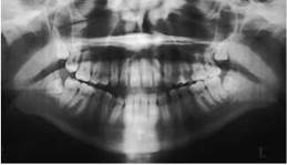
The problems of overlap in the premolar/molar region

The presence of air between the dorsum of the tongue and the hard palate. This produces a band of relative overexposure of the roots of the maxillary teeth and the alveolar bone

Incorrect positioning of the patient resulting in the presence of the dense radio-opacity of the spine in the midline of the panoramic image. The patient has moved throughout the exposure in a vertical direction. This is evidenced by the undulating outline of the lower border of the mandible and that of the hard and soft palate
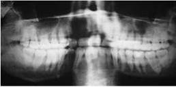
Patient positioned too far from the film resulting in the horizontal magnification of the anterior teeth and also blurring of the teeth. Incorrect positioning has also resulted in the production of secondary images of the mandible. These are seen as dense radio-opacities overlying the posterior maxillary and mandibular teeth
Essential image characteristics
• Edge-to-edge incisors.
• No removable metallic foreign bodies.
• No motion artefacts.
• Tongue against roof of mouth.
• Minimization of spine shadow.
• No antero-posterior positioning errors.
• No mid-sagittal plane positioning errors.
• No occlusal plane positioning errors.
• Correct positioning of spinal column.
• There should be good density and adequate contrast between the enamel and the dentine. (Use of a wide-latitude film is recommended.)
• Name/date/left or right marker all legible.
• Correct anatomical coverage, depending upon clinical application, i.e. limit area covered to clinical needs.
• No cassette/screen problems.
• Adequate processing techniques.
• No pressure marks on film.
• No roller marks (automatic processing only).
• No evidence of film fog.
• No chemical streaks/splashes/contamination.
• No evidence of inadequate fixation/washing.
• Name/date/left or right markers all legible.
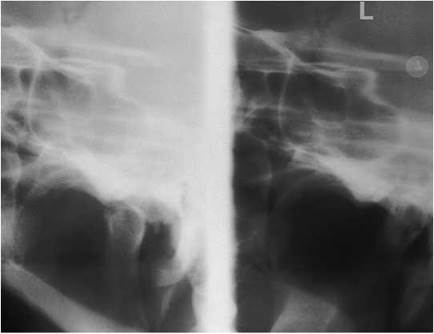
Sectional image of the left temporo-mandibular joint region
Image acquisition
Limitations of resolution imposed by the image receptor, exposure parameters and processing conditions
There is an inevitable reduction in resolution when using screen film. In addition, the exposure factors and processing conditions profoundly influence the perception of detail.
The quality of panoramic films is heavily dependent upon careful attention to technique and processing. Failure to observe these principles has been reported in a recent study (Rushton et al. 1999), which found that one-third of all panoramic films taken were diagnostically unacceptable.
Dose reduction in panoramic radiography
Newer panoramic equipment incorporates improved methods of X-ray generation, such as direct current generators. It also employs field limitation, which enables the operator to image selected areas of designated interest, thereby reducing the dose to the patient. Further dose reduction is achieved by the provision of a variable mA and kVp facility, allowing the equipment to be used with faster film/screen combinations.
Recent advances in panoramic imaging
Newer panoramic equipment, combined with linear tomography, offers greater versatility for the clinician. Most manufacturers provide field-size limitation as standard. These programmes may include some or all of the following: jaws, maxillary sinuses, temporo-mandibular joint (TMJ) programmes, and a child programme. Some manufacturers offer digital sensors as an alternative to film/screen combinations.
Many panoramic machines now include an optional cephalometric facility. These combined machines may have a separate cephalometric tube head, or the machine is converted rapidly from panoramic to cephalometric mode with a simple switch.
Image acquisition (contd)
Patient preparation
• If the patient is wearing a bulky coat, then they should be asked to remove it as it can interfere with the rotational movement of the panoramic equipment.
• The patient should remove all radio-opaque objects from the head and neck areas. These include spectacles, metallic hair clips at the neckline on the back or side of head, hearing aids, earrings, tongue studs, nose jewellery and necklaces. This instruction also includes intra-oral devices, such as com- plete/partial dentures and removable orthodontic appliances. High-necked sweaters with metal zippers/fasteners should also be removed. Chewing gum appears as a radio-opaque mass on the image and should be disposed of before imaging.
• If the patient is unable to remove earrings from the lobule of the ear, then the lobule and attached earring should be folded inwardly on the anti-tragus and taped to the helix/anti-helix of the external ear. The use of this technique ensures that the ghost images of the earrings will not appear on the final image.
General comments
• The unit should be readied in the start position and raised sufficiently to allow the patient to walk into the equipment.
• Depending on the type of equipment used, the examination can be carried out with the patient either standing or seated.
• Careful explanation of the procedure must be given to the patient, as the exposure times vary from 12 to 20 s.
• In view of the exposure time involved, this technique should not be used to image the following patients:
- children unable to remain motionless for the duration of the 12-20-s exposure;
- patients suffering from medical conditions resulting in uncontrollable involuntary movement and lack of coordination.
Position of patient and cassette
• A 15 X 30-cm cassette should be inserted in the cassette carrier.
• Position a bite block on the machine (or chin rest if this is all that is available).
• Ask the patient to walk straight into the machine, gripping the handles if available, and ask them to adopt an upright stance, the so-called 'ski position'. Often patients are afraid of the equipment and hence enter tentatively, with their neck craning forward.


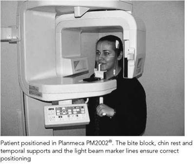
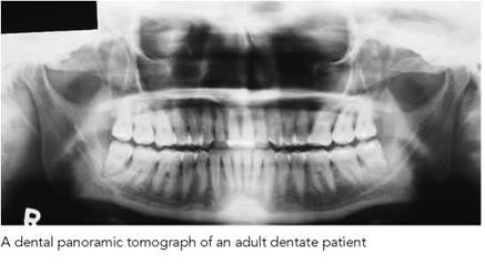
Image acquisition
• The patient’s head should be tilted down towards the floor, so that the Frankfort plane is parallel to floor. In this position, ala-tragus is five degrees caudad.
• Turn on the positioning lights:
- the sagittal plane light should be down the middle of the face;
- the Frankfort plane should be five degrees down from the ala-tragus line;
- the antero-posterior light should be centred distal to the upper lateral incisor (i.e. the lateral/canine inter-proximal space).
• Adjust the height of the machine to the patient, not vice versa.
• Ask the patient to bite into the bite block groove. Check that the upper and lower incisors are both in the groove. In patients with a prominent mandible relative to the maxilla (i.e. class III patients), at least ensure that the upper incisors are in the groove.
• Have the patient rest their chin on the chin rest. If the chin is not on the support, or if the cassette is too far below the mandible, then adjust to prevent the image being positioned too high with consequent loss of the upper portion of the image.
• Stand behind the patient and check the symmetry of position. Adjust if needed by holding the shoulders.
• Close the head restraints.
• Make any fine adjustments at this point.
• Ask the patient to close their lips and press their tongue to the roof of their mouth. The latter instruction is particularly important, since if it is not done a dark radiolucent shadow of the air space above the tongue will obscure the apices of the maxillary teeth. Closing the lips around the bite block reduces the air shadow, which can be mistaken for caries where it overlies the dentition in the premolar region.
• Explain again that the patient must stay absolutely still for about 20 s.
• Make the exposure.
Problems with panoramic radiography
This technique is plagued with problems relating to positioning errors. The more common positioning errors and those related to movement are outlined in the table on the next page.
Problems with panoramic radiography
Common panoramic film faults and how to correct them
|
Panoramic film fault |
Appearance of fault |
Remedy |
|
Anterior teeth positioning errors Head too far forward, i.e. dental arch positioned anterior to focal trough Head too far back, i.e. dental arch positioned posterior to focal trough |
Narrow unsharp image of anterior teeth present; spine overlaps the rami Wide unsharp image of anterior teeth present; TMJ region not evident |
Ensure occlusal plane is tilted downward slightly and the teeth are biting in the grooves on the bite block, as outlined in procedures |
|
Mid-sagittal plane positioning errors Head off-centre Tilting of the head Twisted position of patient |
Mid-sagittal plane off-centre, rami and posterior teeth unequally magnified; side tilted towards X-ray tube enlarged; side closer towards the film looks smaller |
Ensure correct sagittal position of the patient Ensure interpupillary (interorbital) line is parallel |
|
Occlusal plane positioning errors Excessive downward angulation (patient’s chin too far down) |
Severe curvature of the occlusal plane; lack of definition of the lower incisors |
Ensure correct position of occlusal plane |
|
Upward over-angulation (patient’s chin too far up) |
Flattening of occlusal plane, superimposition of apices of maxillary teeth on hard palate; image of anterior teeth unsharp |
|
|
Spinal column positioning error |
Underexposed region in midline of image due to excessive attenuation of energy of beam by spinal column; appears as dense radio-opacity |
Ensure patient adopts ‘ski position’; operator must correct position before exposure if patient slumps forward |
|
Patient’s shoulder interfering with movement of cassette |
Slows cassette, resulting in dark band due to prolonged exposure in region where obstruction occurred |
Patient usually has short neck, elevate chin until ala-tragus line is parallel to floor; positioning cassette 1 cm higher may also help |
TMJ, temporo-mandibular joint.

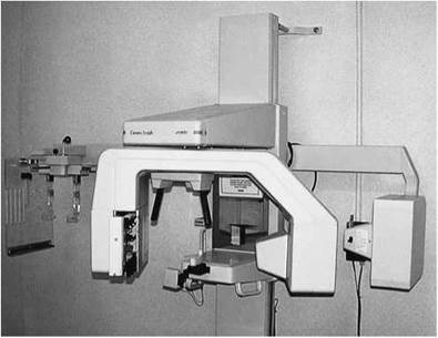
Cephalometric attachment to a panoramic unit
Cephalometric radiography ensures standardization and reproducibility of the images taken.
Lateral and postero-anterior projections are used as part of the initial evaluation of patients who are being considered for orthodontic treatment and/or orthognathic surgery. The technique is also used in the assessment of dentofacial abnormalities.
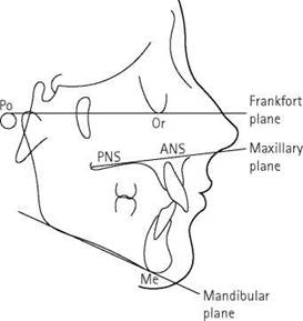
A diagram showing the main cephalometric planes

A diagram illustrating the SNA and SNB lines
X-ray equipment features
The equipment can be stand-alone (i.e. existing X-ray equipment employed with a separate cephalostat). More commonly, however, the equipment is an integral component of a panoramic unit. The cephalostat (or craniostat) provides the mechanism by which the projection is standardized. It consists of two Perspex arms with attached ear pieces/rods to position the patient accurately.
Stand-alone equipment uses a fixed FFD of 200 cm, whilst that employed in combined panoramic/cephalometric equipment is about 150 cm. Whichever method is used, the longer FFD ensures that the beam is parallel, thereby minimizing magnification in the image. It is important that the X-ray equipment used has sufficient output to produce a final image exhibiting adequate penetration.
A filter attenuates the beam in the anterior regions so that the soft tissues of the face can also be demonstrated on one film. Prepatient image enhancement is obtained when the filter is attached to the tube head covering the anterior part of the emerging beam. Post-patient image enhancement is achieved by placing a filter between the patient and the anterior part of the cassette. The former technique is preferable, as, in this position, the filter leaves no line of demarcation on the film and also provides dose reduction. A beam collimator must be incorporated at the tube head to limit the beam to those areas containing the main cephalometric points (British Society for the Study of Orthodontics and the British Society of Dental and Maxillofacial Radiology, 1985; Isaacson and Thom, 2001).
Lateral projection
The projection is a standardized true lateral projection of the skull.
Position of patient and cassette
• The patient sits or stands inside the cephalometric unit, with the sagittal plane vertical and parallel to the cassette.
• The Frankfort plane should be horizontal.
• The head is immobilized by guiding the ear pieces carefully into the external auditory meati. Metal circular markers within the ear pieces allow the operator to rapidly recognize off-centring of the cephalostat.
• The nose support is positioned against the nasion.
• A wedge-shaped filter is positioned so that it will be superimposed on the face, with its thick edge placed anteriorly.
• The patient is instructed to close their mouth and to bite together on their back teeth (i.e. in centric occlusion). Some children find this difficult to do, so it is worth checking before exposing the radiograph.
• The lips should be relaxed.
Direction and centring of the X-ray beam
• The direction and centring of the X-ray beam will normally be fixed. The horizontal beam is centred on the external auditory meati.
Essential image characteristics
• No removable metallic foreign bodies.
• No distortion due to movement.
• Frankfort plane perpendicular to the film.
• No anterior-posterior positioning errors.
• No sagittal plane positioning errors.
• No occlusal plane positioning errors.
• Teeth in centric occlusion (stable and natural intercuspation).
• Lips relaxed.
• Exact matching of external auditory meati with positioning devices.
• Visibility of all cephalometric tracing points required for analysis.
• Visibility of all anterior skeletal and soft tissue structures.
• Good density and contrast.
• No cassette/screen problems.
• No pressure marks on film.
• No roller marks (automatic processing only).
• No evidence of film fog.
• No chemical streaks/splashes/contamination.
• No evidence of inadequate fixation/washing.
• Name and date legible.
Radiological considerations
The use of beam collimation has dramatically reduced the dose
to patients whilst adequately imaging the patient without loss of
the information that is necessary for orthodontic or orthognathic
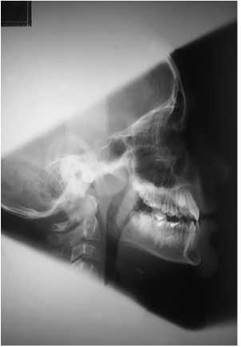
True cephalometric lateral skull radiograph. Images of metal ear rods are superimposed over one another and image displays optimal collimation

The cephalostat

True cephalometric lateral skull radiograph with images of metal ear rods separated indicating 'off centring'

Positioning for the true cephalometric lateral skull radiograph diagnosis (British Society for the Study of Orthodontics and the British Society of Dental and Maxillofacial Radiology, 1985). The wedge collimation limits the dose to the superior aspects of the calvarium above the orbits and to the lower aspects of the cervical spine. Unfortunately, when using modern panoramic equipment, it is impossible with some models to access the tube head to add the additional wedge collimation.
Cephalometric analysis
Cephalometric analysis uses reference lines and points to evaluate underlying skeletal developmental discrepancies. The analysis involves the identification of certain hard and soft tissue landmarks evident on a standardized true lateral projection of the skull. These are subsequently either traced manually from the radiograph onto an overlying sheet of paper or digitally recorded. The latter technique has simplified the process and also provides the clinician with a range of cephalometric analysis packages (i.e. Eastman, Rickett, McNamara etc.) as standard within the software. Using either technique results in the clinician obtaining quantitative measurements with which to evaluate the patient.
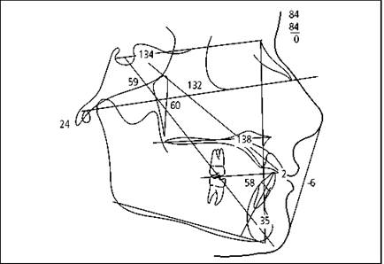
Digitized tracing and analysis
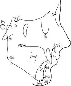
A diagram showing the main cephalometric points
Cephalometry
Lateral projection
The main cephalometric points are listed below in alphabetical order and are shown in the lower figure opposite:
Anterior nasal spine (ANS): The point or tip of the bony nasal spine.
Articulare (Ar): The point of intersection of the projection of the surface of the neck of the condyle and the inferior surface of the basi-occiput.
Gnathion (Gn): The most anterior and inferior point on the bony symphysis of the mandible. It is equidistant from the pogonion and the menton.
Gonion (Go): The most posterior and inferior point on the angle of the mandible.
Infradentale (Id): The most anterior point of the alveolar crest between the lower incisors.
Menton (Me): The lowest point on the mandibular symphysis. Nasion (N): The most anterior point on the frontonasal suture. Orbitale (Or): The most inferior point on the infra-orbital margin.
Pogonion (Pog): The most anterior point of the bony chin.
Point A or Subspinale (A): This is the deepest point on the maxillary profile between the anterior nasal spine and the alveolar crest. Point B or Supramentale (B): This is the deepest point on the concavity of the mandible between the point of the chin and the alveolar crest.
Porion (Po): The highest point on the bony external acoustic meatus. It has been suggested that one takes the highest point of the earpieces of the cephalostat.
Posterior nasal spine (PNS): The point or tip of the posterior spine of the palatine bone of the hard palate.
Prosthion (Pr): The most anterior point of the alveolar crest in the pre-maxilla.
Sella (S): The mid point of the sella turcica.
The main cephalometric planes and angles are listed below and are outlined in the two figures on p. 325.
Frankfort plane: A plane transversing the skull and represented by a line joining the porion and the orbitale.
Mandibular plane: This line causes confusion as a variety of definitions have been applied to describe it. The simplest way to locate the mandibular line is to draw a line from the menton tangential to the lower border of the mandible at the angle. Other definitions include:
• A line joining the gnathion and gonion.
• A line joining the menton and gonion.
Maxillary plane: A line joining the anterior and posterior nasal spines.
SN plane: A line joining the sella and the nasion.
SNA: This relates the antero-posterior position of the maxilla, represented by the A point, to the cranial base.
SNB: This relates the antero-posterior position of the mandible, represented by the B point, to the cranial base.
Postero-anterior projection
Most cephalometric equipment has the facility to allow this projection to be taken. It is an important view in assessing patients with facial asymmetry.
Position of patient and cassette
• The equipment is rotated through 90 degrees.
• The patient is set up as for a postero-anterior projection of the mandible.
• The orbito-meatal baseline is parallel to the floor.
• The head is immobilized using ear pieces inserted into the external auditory meati.
Direction and centring of the X-ray beam
• The horizontal X-ray beam is fixed.
• The central beam is centred through the cervical spine at the level of the rami.