
Benajmin Berte, MD, F Sacher, MD, Pierre Jaïs, MD
BACKGROUND OF VT ABLATION
Catheter ablation of ventricular tachycardia (VT) is effective and particularly useful in patients with frequent defibrillator interventions.3,4 Various substrate modification techniques have been described for unmappable or hemodynamically intolerable VT. Noninducibility is the most frequently used end point but is associated with significant limitations, so the optimal end point remains unclear. Elimination of late potentials and/or local abnormal ventricular activities (LAVAs) during sinus rhythm or ventricular pacing recently showed to be a useful and effective end point for substrate-based VT ablation.1,2,3,5
DEFINITION OF LAVA
LAVA is the abbreviation for local abnormal ventricular activity. These potentials are due to surviving bundles in fibrotic scar, poorly coupled to the healthy myocardium. We prefer to use this term to include the abnormal signals critical to VT that are occurring during the QRS because abnormal activity is not always late: it can occur anytime during the far-field QRS complex. It is a collective term for all abnormal ventricular signals; all late potentials (LPs) are LAVAs but not all LAVAs are LPs. LAVA lateness is measured from the onset of QRS to the end of the LAVA signal.
TABLE 21-1 Characteristics of LAVA
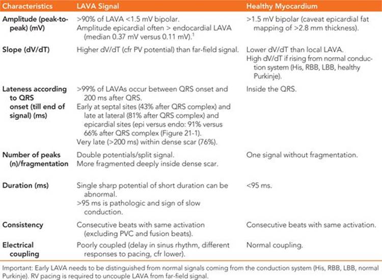

FIGURE 21-1 (A) Late LAVA lateral and early LAVA septal. (B) Earlier LAVA endocardial and later LAVA epicardial. This also illustrates the longest delays in the dense scar. Reproduced with permission from Komatsu Y, Daly M, Sacher F, et al. Electrophysiologic characterization of local abnormal ventricular activities in postinfarction ventricular tachycardia with respect to their anatomic location. Heart rhythm : the official journal of the Heart Rhythm Society 2013:Nov;10(11):1630-1637.
PREPROCEDURAL IMAGING AND LAVA CHARACTERISTICS
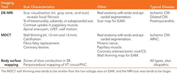
Preprocedural imaging can help identify a scar region through delayed gadolinium enhancement on magnetic resonance imaging (DE-MRI), or wall thinning using multidetector CT (MDCT), indicating the need for epicardial access and preventing potential complications by accurate localization of the coronaries and the phrenic nerve. Scar identified as DE-MRI and wall thinning on MDCT scan are well correlated with the low voltage area on the EAM system and the appearance of LAVA6. DE-MRI is ideal to depict the scar versus healthy myocardium, except in the presence of ICD, which precludes good quality images. This is why MDCT can be used as a surrogate, especially when wall thinning is present at the scar area. Different image possibilities are shown in Table 21-2. LAVA probability differs by disease entity. In ischemic cardiomyopathy (ICM) we observed LAVA predominantly endocardially, with epicardial involvement depending on the degree of transmurality. Ninety percent of LAVA is seen in zones with wall thinning of <5 mm with very late LAVA occurring almost exclusively in a <3 mm wall thinning area.7 No LAVAs are seen >20 mm outside the scar border zone, and most LAVAs appear in the border zone.6,7 Nonischemic cardiomyopathy (NICM) is a more heterogeneous entity. Dilated cardiomyopathy (DCM) shows most LAVA perivalvular. Postmyocarditis patients typically present with only epicardial LAVA and complete normal endocardial mapping.7 Arrhythmogenic right ventricular cardiomyopathy (ARVC) shows most LAVA at the epicardial site with some endocardial LAVA because of wall thinning.
TABLE 21-2 Preprocedural Imaging
TECHNIQUES TO UNMASK LAVA
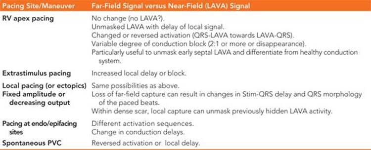
The signal recorded with a mapping catheter is always a combination of far-field and near-field potentials. Figure 21-2 shows the difference between far-field and near-field signals. In order to unmask local abnormal activity, several different pacing techniques can be used, as explained in Table 21-3.
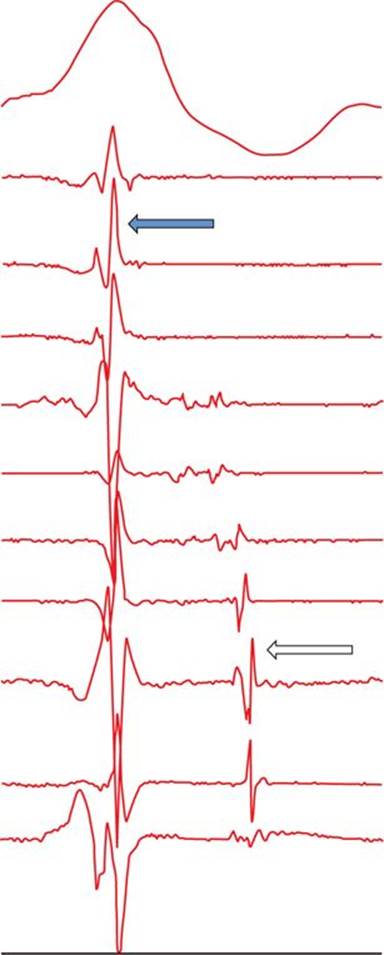
FIGURE 21-2 Differentiation between far-field and near-field signals: ECG shows ventricular QRS signal. Multipolar catheter recording shows far-field and near-field signals. Far-field signals are synchronous, of higher amplitude, have lower dV/dT (black arrow). In contrast, near-field signals are delayed as they are generated by local, poorly coupled surviving bundles (white arrow). They have sharper dV/dT and lower amplitude.
TABLE 21-3 Techniques to Unmask LAVA Activity
MAPPING OF LAVA DURING SR OR VT
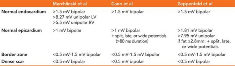
In sinus rhythm, most centers perform automatic substrate mapping with an electroanatomic mapping (EAM) system. Different cut-offs for normal and abnormal myocardium are used in unipolar or bipolar mode. Epicardial fat can make epicardial substrate mapping more difficult; it can mimic low voltage areas but will not show fragmentation or delayed activation. Therefore, some centers include special EGM characteristics together with low voltage as criteria for defining scar regions such as wide, split, late, and fragmented signals to the low voltage area.8 True intramural or septal scar can be difficult to identify and preprocedural imaging, pacing maneuvers (delayed transmural conduction time [>40 ms] and fractionated, late, split, and wide [>95 ms] potentials on the left-sided septum during RV pacing), and/or unipolar voltage map (<8.3 mV unipolar septal mapping from inside the LV) can be helpful.8-14It is our practice to create a high density endocardial (and epicardial) substrate-based voltage map with special annotation of all LAVA points and sites with good pace-maps. We perform automatic mapping in most ICM patients, but in NICM, we tend to manually adapt the substrate map toward the near-field (LAVA) signal in order to create better scar delineation, especially during epicardial mapping, as automatic bipolar and unipolar mapping can be normal in those cases. Some operators change the color scale of the substrate map to visualize (critical or bystander) channels.15
During VT, activation mapping and entrainment mapping is performed. In certain cases, LAVA can be recorded during the whole VT cycle length to define the entire VT circuit and isthmus (Figure 21-3). Ideal ablation sites are within the critical isthmus with demonstration of mid-diastolic LAVA, concealed entrainment with PPI-TCL<30 ms, Stim-QRS interval >40 to 70 ms, and cessation of VT during ablation. But ablation would be continued after VT termination to reach the end point of LAVA elimination.
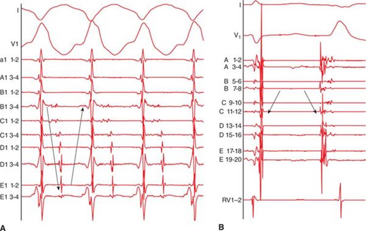
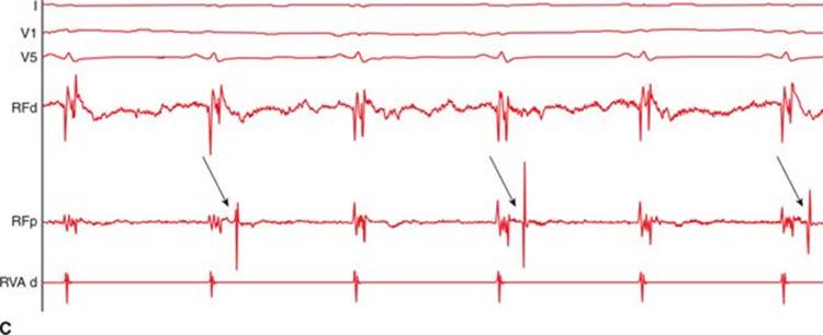
FIGURE 21-3 (A) Multipolar mapping of LAVA covering almost whole cycle length during VT. (B) Reversed activation sequence between sinus beat and ectopic beat. (C) 2:1 block of a LAVA signal.
ABLATION OF LAVA
Over the years, different VT ablation strategies have been investigated: circular lesions around the whole scar, lines to connect islands of surviving tissue in order to block channels, critical isthmus ablation, and recently, scar homogenization and LAVA ablation.16-18 These techniques can be complementary.
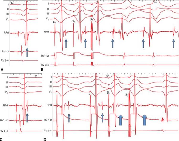
FIGURE 21-4 Role of LAVA in the induction of ventricular tachycardia (VT) and the influence of ablation. Before radiofrequency energy delivery (RF): (A) At first sight, the local ventricular electrogram during baseline-paced rhythm looks simple. However, in the terminal portion of this simple-looking signal, a very high-frequency component (LAVA) can be identified. (B) Programmed electric stimulation from the right ventricle (RV) unmasks the LAVA potential by increasing the delay from the far-field signal. The delay observed during RV pacing suggests poor coupling of the muscle bundle generating the LAVA signal. The delay is maximal with S3, which is associated not only with a change in the polarity of LAVA but also with the induction of VT. Post-RF energy delivery: (C). After delivery of RF energy, there is a remarkable delay (see A) between the far-field ventricular signal and LAVAs during baseline-paced rhythm. (D) Repeat programmed electric stimulation from the RV results in the absence of LAVA signals after the far-field ventricular potential during S2 and S3 (open arrows). The absence of LAVAs is associated with an inability to induce the VT. Although ablation has rendered VT noninducible, further RF energy application is indicated to completely eliminate the LAVAs. Reproduced with permission from Jais P, Maury P, Khairy P, et al. Elimination of local abnormal ventricular activities: a new end point for substrate modification in patients with scar-related ventricular tachycardia. Circulation 2012;May 8;125(18):2184-2196.
TABLE 21-4 Different Voltage Criteria for Substrate-Based Mapping
STANDARDIZED APPROACH FOR VT ABLATIONS
Preparation
First, the usual interrogation and examination of the patient is performed. Imaging is performed to exclude intraventricular thrombus, delineate the scar, and provide further anatomical information. In absence of ICD, MRI is systematically performed, if possible associated with MDCT imaging. In others, MDCT imaging only is performed. The ICD logs are examined and the ICD deactivated. Twelve-lead ECG of the clinical VT is evaluated to acquire information about the exit site, cycle length, and possible multiple morphologies. Preprocedural imaging helps to plan the access needed (endocardial only, combined endocardial, and epicardial or epicardial only) and is imported in the EAM system for image integration purposes (location of scar, phrenic nerve, coronary arteries, papillary muscles). Hemodynamic stability and the need for circulatory support is assessed. Contraindications for pericardial access is evaluated (low platelet count <50.000, uninterrupted NOAC use, prior cardiac surgery, prasugrel/clopidogrel use).
Endo and/or Epicardial Access
If epicardial access is planned, an RV apex catheter (check threshold for RV pacing) is positioned before performing a subxyphoidal anterior percutaneous puncture with a tuohy needle, fluoroscopy in left lateral projection and using minimal doses of contrast (Figure 21-6).1 A long guidewire is inserted, and after careful checking of correct pericardial position (inserting about 40 cm confirms that the guidewire is not in a cardiac chamber), a steerable sheath (epicardial Agilis or short curved Agilis) is inserted in the pericardial space. Heparin is commenced after the pericardial puncture. Endocardial access is obtained with transseptal or retrograde aortic access, depending on cases.
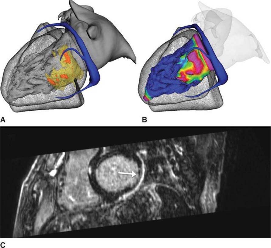
FIGURE 21-5 Patient with a known history of an earlier acute coronary syndrome and LAD lesion in whom an endocardial-only approach was planned. DE-MRI a day before the procedure showed subepicardial basal scar only. A new patent interrogation was performed and suggestive for a postmyocarditis scar. A combined endo- and epicardial approach was then decided, and only epicardial LAVA was found and ablated. (A) MDCT wall-thinning imaging. (B) Color-coded 3-D wall thickness map. (C) DE-MRI short axis view shows subepicardial scar only (white arrow).
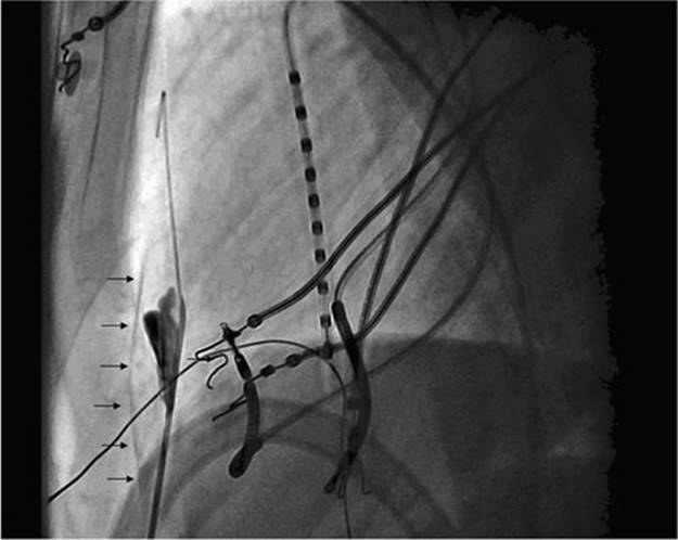
FIGURE 21-6 Lateral fluoroscopic projection showing the subxiphoid pericardial puncture with a Tuohy needle. The course of the needle in the substernal space is almost tangential to the posterior border of the sternum. It penetrates the parietal layer of the pericardium anteriorly as visualized from the contrast staining the anterior pericardium. Intrapericardial entry is confirmed with contrast trickling into the pericardial space (arrows). The guidewire is then inserted. Reproduced with permission from Jais P, Maury P, Khairy P, et al. Elimination of local abnormal ventricular activities: a new end point for substrate modification in patients with scar-related ventricular tachycardia. Circulation 2012;125:2184-96.
Substrate Mapping
An endocardial and/or epicardial anatomical and substrate map is made with a bipolar cut-off of <0.5 mV (scar), 0.5-1.5 mV (border zone), and above >1.5 mV (normal) used as automatic standard settings for endo- and epicardial mapping. In NICM with subepicardial scar only, manual adjustment of the voltage map toward the near-field LAVA signal is performed. All LAVA signals are annotated on the EAM system, and maneuvers to unmask LAVA are performed. Multipolar mapping (Pentaray catheter) allows quick and high-density mapping (off-label use epicardially) of possible LAVA.
VT Induction
After the completion of the substrate map in sinus rhythm, an attempt to induce VT is performed. Figure 21-7 shows an induced monomorphic VT. Depending on the hemodynamic stability, activation mapping and entrainment mapping is performed (cf LAVA ablation). LAVA sites in sinus rhythm may match with mid-diastolic activity during VT. Figure 21-8 shows an activation map in sinus rhythm and during VT. Figure 21-9 shows LAVA in almost the entire VT cycle length on the mapping catheter. The mid-diastolic LAVA signal is ablated. and VT terminates at that site. Ablation is continued in SR to eliminate all LAVA.

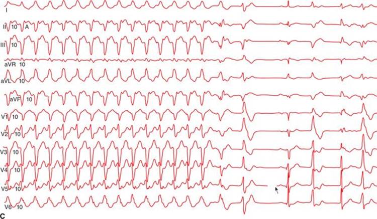
FIGURE 21-7 Patient with a previous inferior myocardial infarction and scar-related VT. (A) Clinical VT and entrainment/pace-mapping shows manifest fusion with short Stim-QRS <40 ms. (B) Almost perfect pace-map 11/12 with clinical VT, Stim-QRS >40 ms. (C) Ablation during stable clinical VT with prolongation and restoration of sinus rhythm during ablation.
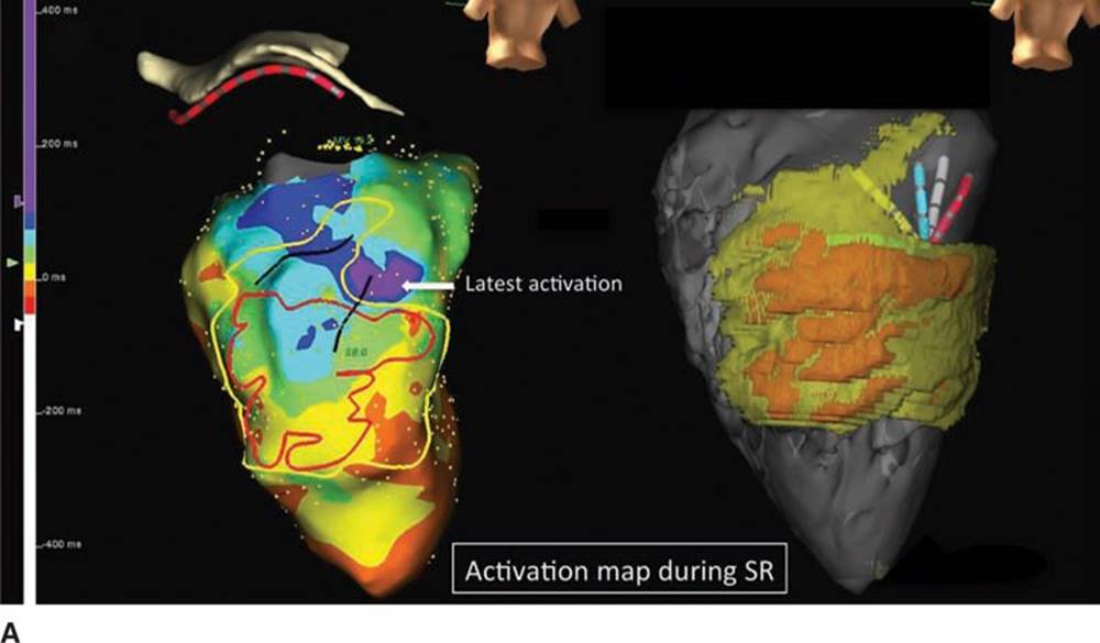
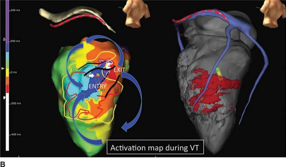
FIGURE 21-8 Patient with a previous inferior myocardial infarction. (A) On the left, the activation map during sinus rhythm shows latest activation inside the isthmus toward the exit site (purple zone), deep inside the scar in the laterobasal region. The figure on the right shows a three-dimensional MDCT wall thinning area of <2 mm in red and <4 mm in yellow. (B) On the left, the activation map during clinical VT shows short, funnel-shaped isthmus with “figure-of-eight” activation. Ablation is performed at mid isthmus. On the right, a three-dimensional MDCT segmentation model is shown. The red area shows wall thinning of <2 mm. On the left in both A and B, encircling of the wall thinning areas <2 mm (in red) and <4 mm (in yellow <4 mm) are shown. Wall thinning underestimates the scar area.
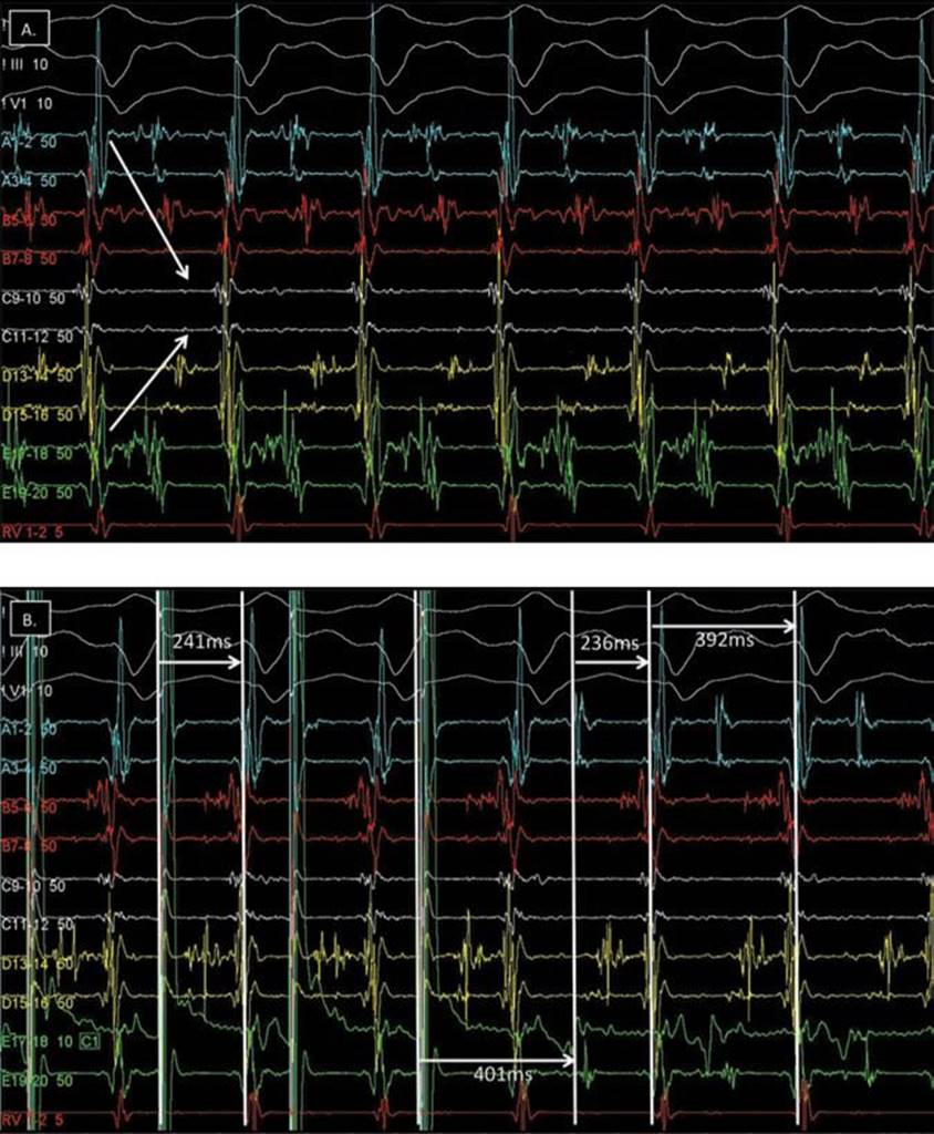
FIGURE 21-9 Same patient with previous myocardial infarction. (A) Multipolar mapping during clinical VT shows LAVA during almost whole cycle length (entry-isthmus-exit: arrows). (B) Entrainment with long Stim-QRS 241 ms, concealed fusion, Stim−QRS = EGM−QRS and PPI−TCL = 401−392 = 9 ms: entry site inside isthmus. (C) Ablation midway isthmus still shows mid-diastolic potentials (white arrow) and stops VT with prolongation (not PVC) in 2 sec.
Ablation During VT
LAVA sites are ablated during VT. Figure 21-9 shows LAVA in almost the whole VT cycle length on the mapping catheter. The mid-diastolic LAVA signal is ablated, and VT terminates at that site.
Ablation in SR
After ablation during VT, if VT cannot be induced or if only rapid hemodynamically unstable VT is induced (with need for DC shock), substrate ablation is performed during sinus rhythm.
All LAVAs are targeted aiming at elimination or isolation. LAVAs are first ablated at the border zone—where they are shortly coupled—before considering ablation deeper inside the scar. This strategy may result in the elimination of the late LAVA inside the dense scar with less ablation than a systematic RF delivery at the entire scar surface would require.19 Ideal ablation sites show local LAVA, have a good or perfect pace-map compared to the VT morphology (>10/12), and demonstrate local capture with long Stim-QRS time >40 to 70 ms (sign of slow conduction). The procedural end point is complete elimination of all LAVA.
Checking the Ablation End Point
After all possible LAVA elimination, a new substrate map is made, and multipolar mapping is repeated to check for persisting LAVA signals. Further ablation is performed if needed. Inducibility is checked at the end of the procedure.
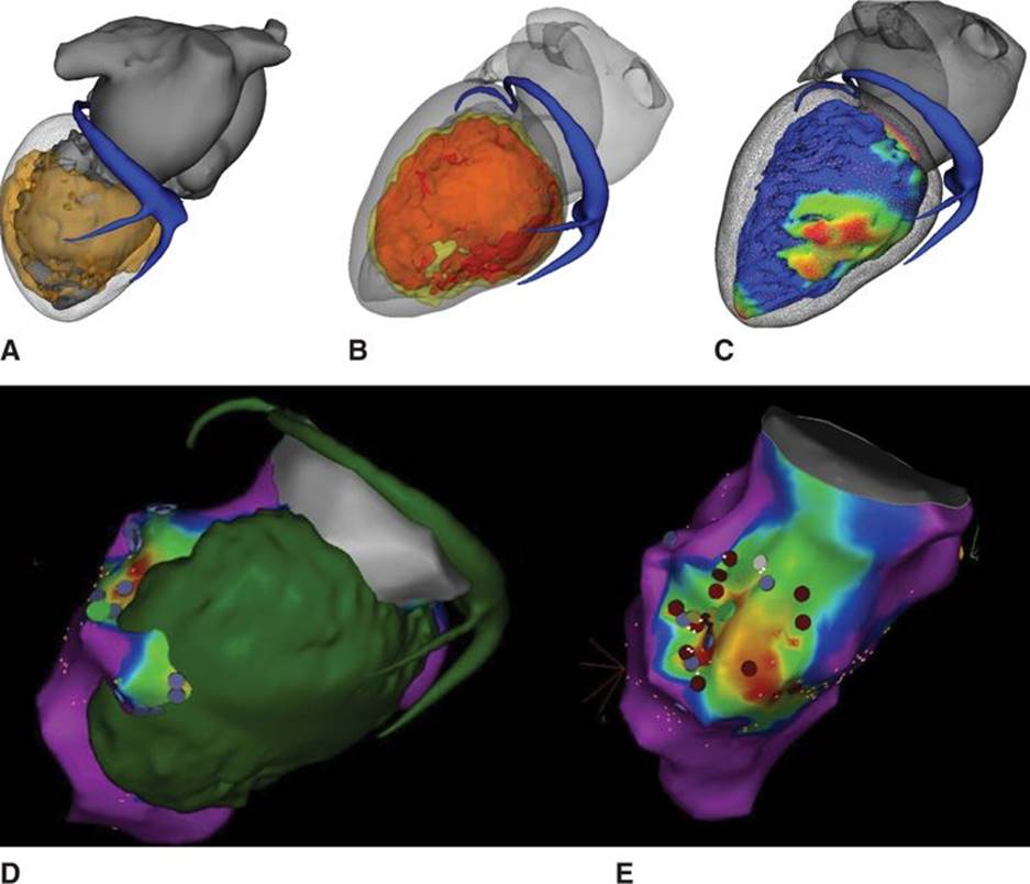
FIGURE 21-10 Patient with a previous myocardial infarction. (A) Inferior scar on DE-MRI. (B) Wall thinning on MDCT. (C) Color-coded wall thickness map. All are integrated in the EAM system using the MUSIC platform. (D) Image integration into the EAM system with merge of MDCT/MRI model with DE scar visualization and an endocardial bipolar voltage map. (E) Good correlation between scar on MRI and low voltage on EAM. LAVA points are tagged in purple and ablation points in red. Mid-diastolic LAVAs are tagged in green.
Postprocedural Management
In case of uncomplicated pericardial puncture, the pericardial sheath is withdrawn at the end. Some authors give intrapericardial corticoids systematically, and others leave a pericardial pigtail for 24 hours.20,21
END POINT OF LAVA ABLATION
The only clear end point for LAVA ablation is complete LAVA elimination. In our experience, all LAVAs are eliminated in 60% to 70% of the patients.1 Endo and epi LAVA elimination requires epicardial ablation in 58% of ICM patients and 82% of NICM patients (paper submitted). Incomplete LAVA elimination is accepted if the patient is hemodynamically unstable. A high risk of complications is expected because of LAVA sites <5 mm from a coronary artery or the phrenic nerve or because LAVA cannot be eliminated with high power, particularly in the case of intraseptal or intramural scar. These complications can often been prevented; preprocedural image integration of CS, coronary arteries, phrenic nerve and periprocedural systematic coronary angiogram, and phrenic pace-mapping if epicardial ablation is used are very helpful.
PROGNOSIS OF LAVA ABLATION
Emerging data demonstrate that complete LAVA elimination has a significantly better prognosis and mortality benefit compared to incomplete elimination, irrespective of VT inducibility (Figure 21-11).
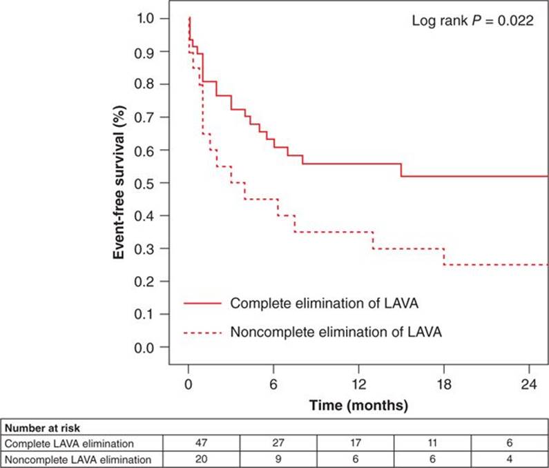
FIGURE 21-11 Kaplan-Meier curves depict freedom from recurrent ventricular tachycardia or death in patients with and without complete elimination of local abnormal ventricular activities (LAVAs). Jaïs et al, with permission.1
CONCLUSION
LAVA ablation with the aim for complete LAVA elimination is feasible and associated with a better clinical outcome. It has the advantage offering a clear end point with the ability to work in sinus rhythm.
REFERENCES
1. Jais P, Maury P, Khairy P, et al. Elimination of local abnormal ventricular activities: a new end point for substrate modification in patients with scar-related ventricular tachycardia. Circulation. 2012;125(18):2184-2196.
2. Komatsu Y, Daly M, Sacher F, et al. Electrophysiologic characterization of local abnormal ventricular activities in postinfarction ventricular tachycardia with respect to their anatomic location. Heart Rhythm. 2013;10(11):1630-7.
3. Aliot EM, Stevenson WG, Almendral-Garrote JM, et al. EHRA/HRS Expert Consensus on Catheter Ablation of Ventricular Arrhythmias: developed in a partnership with the European Heart Rhythm Association (EHRA), a Registered Branch of the European Society of Cardiology (ESC), and the Heart Rhythm Society (HRS); in collaboration with the American College of Cardiology (ACC) and the American Heart Association (AHA). Heart Rhythm. 2009;6:886-933.
4. Zipes DP, Camm AJ, Borggrefe M, et al. ACC/AHA/ESC 2006 guidelines for management of patients with ventricular arrhythmias and the prevention of sudden cardiac death—executive summary: a report of the American College of Cardiology/American Heart Association Task Force and the European Society of Cardiology Committee for Practice Guidelines (Writing Committee to Develop Guidelines for Management of Patients with Ventricular Arrhythmias and the Prevention of Sudden Cardiac Death). Developed in collaboration with the European Heart Rhythm Association and the Heart Rhythm Society. Eur Heart J. 2006;27:2099-2140.
5. Arenal A, Glez-Torrecilla E, Ortiz M, et al. Ablation of electrograms with an isolated, delayed component as treatment of unmappable monomorphic ventricular tachycardias in patients with structural heart disease. J Am Coll Cardiol. 2003;41:81-92.
6. Cochet H, Komatsu Y, Sacher F, et al. Integration of merged delayed-enhanced magnetic resonance imaging and multidetector computed tomography for the guidance of ventricular tachycardia ablation: a pilot study. J Cardiovasc Electrophysiol. 2013;24:419-426.
7. Komatsu Y, Cochet H, Jadidi A, et al. Regional myocardial wall thinning at multidetector computed tomography correlates to arrhythmogenic substrate in postinfarction ventricular tachycardia: assessment of structural and electrical substrate. Circ Arrhyth Electrophysiol. 2013;6:342-350.
8. Cano O, Hutchinson M, Lin D, et al. Electroanatomic substrate and ablation outcome for suspected epicardial ventricular tachycardia in left ventricular nonischemic cardiomyopathy. J Am Coll Cardiol. 2009;54:799-808.
9. Haqqani HM, Tschabrunn CM, Tzou WS, et al. Isolated septal substrate for ventricular tachycardia in nonischemic dilated cardiomyopathy: incidence, characterization, and implications. Heart Rhythm. 2011;8:1169-1176.
10. Garcia FC, Bazan V, Zado ES, Ren JF, Marchlinski FE. Epicardial substrate and outcome with epicardial ablation of ventricular tachycardia in arrhythmogenic right ventricular cardiomyopathy/dysplasia. Circulation. 2009;120:366-375.
11. Hutchinson MD, Gerstenfeld EP, Desjardins B, et al. Endocardial unipolar voltage mapping to detect epicardial ventricular tachycardia substrate in patients with nonischemic left ventricular cardiomyopathy. Circ Arrhythm Electrophysiol. 2011;4:49-55.
12. Liuba I, Marchlinski FE. The substrate and ablation of ventricular tachycardia in patients with nonischemic cardiomyopathy. Circ J. 2013;77:1957-1966.
13. Polin GM, Haqqani H, Tzou W, et al. Endocardial unipolar voltage mapping to identify epicardial substrate in arrhythmogenic right ventricular cardiomyopathy/dysplasia. Heart Rhythm. 2011;8:76-83.
14. Wijnmaalen AP, van der Geest RJ, van Huls van Taxis CF, et al. Head-to-head comparison of contrast-enhanced magnetic resonance imaging and electroanatomical voltage mapping to assess post-infarct scar characteristics in patients with ventricular tachycardias: real-time image integration and reversed registration. Eur Heart J. 2011;32:104-114.
15. Perez-David E, Arenal A, Rubio-Guivernau JL, et al. Noninvasive identification of ventricular tachycardia-related conducting channels using contrast-enhanced magnetic resonance imaging in patients with chronic myocardial infarction: comparison of signal intensity scar mapping and endocardial voltage mapping. J Am Coll Cardiol. 2011;57:184-194.
16. Marchlinski FE, Callans DJ, Gottlieb CD, Zado E. Linear ablation lesions for control of unmappable ventricular tachycardia in patients with ischemic and nonischemic cardiomyopathy. Circulation. 2000;101:1288-1296.
17. Reddy VY, Neuzil P, Taborsky M, Ruskin JN. Short-term results of substrate mapping and radiofrequency ablation of ischemic ventricular tachycardia using a saline-irrigated catheter. J Am Coll Cardiol. 2003;41:2228-2236.
18. Carbucicchio C, Ahmad Raja N, Di Biase L, et al. High-density substrate-guided ventricular tachycardia ablation: Role of activation mapping in an attempt to improve procedural effectiveness. Heart Rhythm. 2013.
19. Tung R, Mathuria NS, Nagel R, et al. Impact of local ablation on interconnected channels within ventricular scar: mechanistic implications for substrate modification. Circ Arrhythm Electrophysiol. 2013;6:1131-1138.
20. Sacher F, Roberts-Thomson K, Maury P, et al. Epicardial ventricular tachycardia ablation a multicenter safety study. J Am Coll Cardiol. 2010;55:2366-2372.
21. Sarkozy A, Tokuda M, Tedrow UB, et al. Epicardial ablation of ventricular tachycardia in ischemic heart disease. Circ Arrhythm Electrophysiol. 2013.