Timothy J. Bennett,
David A. Quillen,
James D. Strong
Since its introduction in the early 1960s, fluorescein angiography has become an essential tool in the understanding, diagnosis, and treatment of retinal disorders. While direct examination of the fundus with slit-lamp biomicroscopy and indirect ophthalmoscopy is indispensable in the diagnosis of retinal disease, fluorescein angiography provides additional information concerning the anatomy, physiology, and pathology of the retina and choroid. This diagnostic procedure utilizes a specialized fundus camera or scanning laser ophthalmoscope (SLO) to capture rapid-sequence photographs of the retina following an intravenous injection of fluorescein sodium. Photographic or video images taken as the dye courses through the eye can demonstrate abnormalities within the neurosensory retina, pigment epithelium, sclera, choroid, and optic nerve, providing clinically useful information for nearly the entire spectrum of posterior segment disorders.
CHARACTERISTICS OF FLUORESCEIN
FLUORESCENCE
Fluorescein angiography is an application of the physical phenomenon of fluorescence.[1] Fluorescence is a type of photoluminescence that occurs when susceptible molecules known as fluorophores absorb electromagnetic energy, temporarily exciting them to a higher energy state. As the molecules return to their original energy level, they emit light of a different, usually longer wavelength. Unlike phosphorescence, which continues to occur after the excitation source is removed, fluorescence requires continuous excitation. Once the excitation source is removed, emission of fluorescence stops almost immediately (10?8 s).
Fluorescence occurs naturally in certain compounds and may occasionally be observed in the human eye. Optic nerve drusen, astrocytic hamartomas, lipofuscin pigments in the retina, and the aging human lens are all believed to exhibit natural fluorescence that can be documented with various photographic techniques.
FLUORESCEIN SODIUM
Although commonly referred to as fluorescein, the dye used for fluorescein angiography is actually fluorescein sodium (C20H10Na2O5).[2] It is the water-soluble salt of fluorescein, also known as resorcinolphthalein sodium, or uranine. A member of the xanthene group of dyes, it is a highly fluorescent chemical compound synthesized from the petroleum derivatives resorcinol and phthalic anhydride.[3]The dye was first synthesized in 1871 by Adolf von Baeyer, who later received the Nobel Prize in Chemistry (1905) for his work in organic dyes.
Fluorescein sodium absorbs blue light, with peak excitation occurring at wavelengths between 465 and 490nm. The resulting fluorescence occurs at the yellow-green wavelengths of 520-530nm (Fig. 128.1). Dye concentration and pH can affect the intensity of fluorescence. Maximum fluorescence occurs at a pH of 7.4, but the pH of fluorescein sodium for angiographic use is adjusted to a range of 8-9.8 for stability. In powdered or concentrated solution form, fluorescein sodium appears orange-red in color. Fluorescence is detectable in concentrations between 0.1% and 0.0000001%. In broad-spectrum illumination, diluted fluorescein sodium appears bright yellow-green in color. When illuminated with blue light, the yellow-green color intensifies dramatically.
|
|
|
|
FIGURE 128.1 Excitation and emission. Representative excitation and emission curves of fluorescein sodium. Peak excitation occurs at wavelengths between 465 and 490 nm (blue-green). Peak fluorescence occurs at wavelengths of 520-530 nm (green-yellow). |
The fluorescent properties of this dye have made it useful in a variety of industrial, scientific, military, and medical applications. Fluorescein sodium was the first fluorescent dye used for water tracing purposes.[4] It has been used as a visible marker for search-and-rescue operations, to track and measure flow dynamics of water sources, map subterranean water courses, track hazardous spill dispersion patterns, identify point sources of pollution, and to detect leaks or obstructions in plumbing and sewage systems. In fact, its common use in industrial plumbing led a plumbers union to start the tradition of using fluorescein to stain the Chicago River green for the annual St Patrick's Day celebration.
Many of the medical and ophthalmic applications of fluorescein are analogous to its uses in plumbing or industrial flow dynamics. For example, it has been used for intraoperative assessment of blood flow in surgical resections and grafts with a Wood's Light to excite fluorescence.[5-9] It has also been employed as an intraoperative predictor of intestinal viability,[10,11] as an indicator of local perfusion in gangrene or severe burns,[12,13] and to monitor perfusate leak in systemic tissues during isolated limb perfusion with high dose chemotherapeutic agents.[14] In ophthalmology, topical application of fluorescein sodium is routinely used for applanation tonometry, and as a vital stain in the documentation of ocular surface disorders such as corneal ulcers, abrasions, or other epithelial defects.[15] It is sometimes used to determine tear film breakdown time, check the fit of contact lenses, verify the patency of lacrimal passageways, and to detect leakage of aqueous humor from corneal or conjunctival wounds using the Seidel Test.
HISTORY
In 1881, just a decade after the discovery of fluorescein, Ehrlich observed anterior chamber fluorescence following an injection of fluorescein. In 1910, Burke described fluorescent staining of retinal and choroidal lesions in white light, after ingestion of a mixture of fluorescein in coffee.[16] In the late 1950s, Flocks and co-workers investigated methods to determine retinal circulation times with various dyes, including trypan blue and fluorescein.[17,18] Using a 16 mm movie camera attached to a fundus camera with a carbon arc light, they succeeded in obtaining fluorescein angiograms in cats, but were unsuccessful in attempts on humans due to insufficient light. MacLean and Maumenee performed fluorescein angioscopy with a blue exciter light to diagnose a choroidal hemangioma following intravenous injection in 1960.[19]
In 1959, two medical students, Harold Novotny and David Alvis worked on a research project to develop a photographic technique to estimate blood oxygen concentrations in the retinal vascular bed as a visible segment of the cerebral circulation. They mixed fluorescein with a blood sample and measured it with a spectrofluorometer to determine the excitation and emission wavelengths of fluorescein. They found the peak excitation of fluorescein to be 490nm and peak emission, 520nm. Then they equipped a fundus camera with broadband absorption filters, a Kodak Wratten 47B for excitation and a Kodak Wratten 58 green for the barrier. They confirmed the technique on rabbits and then flipped a coin to see who would be the first human 'patient'. Alvis lost, so he was the subject of the first successful fluorescein angiogram in a human. After their initial success, they refied the technique on numerous patients with diabetes and hypertension. The landmark paper describing their technique was published in the journal Circulation in 1961, after being rejected by the ophthalmic literature as unoriginal work.[20] Following their report, several investigators studied various clinical applications of angiography, quickly establishing the intrinsic value of the technique.[21] Further innovations were made gradually, including improved filter combinations, fast recycling flash units, digital imaging techniques, and SLOs, but the basic principles described by Novotny and Alvis remain unchanged (Fig. 128.2).
|
|
|
|
FIGURE 128.2 Fluorescein angiography, then and now. (a) Photographs from the first fluorescein angiogram by Novotny and Alvis demonstrate significant crossover of their simple filter combination, resulting in incomplete blockage of the exciting wavelengths. Results were also limited by the slow recycle time of the flash unit, more than 12 s between exposures. (b) Modern high-resolution digital fluorescein angiogram demonstrates improvement in technical quality, but the basic technique developed by Novotny and Alvis is essentially the same. |
INDICATIONS AND USES
The most common uses of fluorescein angiography are in retinal or choroidal vascular diseases such as diabetic retinopathy, age-related macular degeneration, hypertensive retinopathy, and vascular occlusions (Table 128.1). For the most part, these are clinical diagnoses. The angiogram is used to determine the extent of damage, to develop a treatment plan or to monitor the results of treatment. In diabetic retinopathy the angiogram is useful in identifying the extent of ischemia, the location of microaneurysms, the presence of neovascularization and the extent of macular edema. In age-related macular degeneration, angiography is useful in identifying the presence, location and characteristic features of choroidal neovascularization for possible treatment with laser photocoagulation, photodynamic therapy, or antiangiogenic medications.
TABLE 128.1 -- Common Diagnostic Uses and Indications for Fluorescein Angiography
|
Diabetic retinopathy |
|
Age related macular degeneration |
|
Subretinal neovascular membrane from other causes (myopic degeneration, histoplasmosis, etc.) |
|
Central retinal vein occlusion |
|
Branch retinal vein occlusion |
|
Central serous chorioretinopathy |
|
Cystoid macular edema |
|
Hypertensive retinopathy |
|
Central retinal artery occlusion |
|
Branch retinal artery occlusion |
|
Retinal arterial macroaneurysms |
|
Pattern dystrophies of the retinal pigment epithelium |
|
Choroidal tumors |
|
Chorioretinal inflammatory conditions |
|
Hereditary retinal dystrophies |
Fluorescein angiography can be very useful in certain degenerative and inflammatory conditions. Some of these conditions exhibit characteristic fluorescence patterns, which support the diagnosis. For example, Stargardts Disease exhibits a 'silent choroid' and a central bulls-eye fluorescence pattern in the macula while acute posterior multifocal placoid pigment epitheliopathy (APMPPE) demonstrates a characteristic 'block early, stain late' pattern.
Angiography has long played a role in advancing the understanding of retinal vascular disorders and potential treatment modalities. A number of multicenter clinical trials utilize fluorescein angiography in investigating new treatment options in diabetic retinopathy, age-related macular degeneration, and retinal vein occlusions.[22]
DOSAGE AND ADMINISTRATION
Fluorescein angiography is performed by injecting fluorescein sodium dye as a bolus into a peripheral vein. The normal adult dosage is 500 mg, and is typically packaged in doses of 5 mL of 10% or 2 mL of 25%. For pediatric patients, the dose is adjusted to 35 mg/10 pounds of body weight.[23] Upon entering the circulation, ?80% of the dye molecules bind to plasma proteins, which significantly reduces fluorescence because the free electrons that form this chemical bond are subsequently unavailable for excitation.[1] The remaining unbound or free fluorescein molecules fluoresce when excited with light of the appropriate wavelength. With a molecular weight of 376, fluorescein diffuses freely out of all capillaries except those of the central nervous system, including the retina.
The dye is metabolized by the kidneys and is eliminated through the urine within 24-36h of administration. During this period of metabolism and elimination, fluorescein has the potential to interfere with clinical laboratory tests that use fluorescence as a diagnostic marker.[24,25] To avoid any false readings, it may be prudent to schedule clinical lab tests either before the angiogram, or postpone testing for a day or two to allow sufficient elimination of the dye. Side effects of intravenous fluorescein include discoloration of the urine for 24-36h and a slight yellow skin discoloration that fades within a few hours. Nursing mothers should be cautioned that fluorescein is also excreted in human milk.[26]
COMPLICATIONS AND ADVERSE REACTIONS
|
Key Features |
|
Fluorescein angiography is well-tolerated by the vast majority of individuals. The most common adverse reactions are transient nausea and occasional vomiting. |
Fluorescein sodium is well tolerated by most patients, but angiography is an invasive procedure with an associated risk of complication or adverse reaction (Table 128.2). Use of fluorescein sodium may be contraindicated in patients with a history of allergic hypersensitivity to fluorescein. Although generally considered safe for patients receiving dialysis, one manufacturer of fluorescein suggests using half the normal dose in dialyzed patients.[27] There are no known risks or adverse reactions associated with pregnancy but most practitioners avoid performing fluorescein angiography in pregnant women, especially in their first trimester.[28-30]
TABLE 128.2 -- Complications and Adverse Reactions
|
Extravasation of dye |
|
Transient nausea |
|
Vomiting |
|
Pruritis |
|
Urticaria |
|
Bronchospasm |
|
Laryngeal edema |
|
Anaphylaxis |
|
Hypotension |
|
Syncope |
|
Seizures |
|
Myocardial infarction |
|
Cardiac arrest |
Historically, adverse reactions occur in 5-10% of patients and range from mild to severe.[31-37] Anecdotal evidence suggests a lower incidence of reaction in recent years and the first large study conducted in over a decade seems to confirm that, reporting a frequency of adverse reaction of just over 1%.[38] Continued improvements in manufacturing processes and implementation of tighter pharmacopeial standards are credited with this reduction and may lead to lower rates of reaction in the future.[39]
Transient nausea and occasional vomiting are the most common reactions and require no treatment. These mild reactions typically occur 30-60s after injection and last for ?1-2 min. Fortunately, they seldom compromise the diagnostic quality of the angiogram. The incidence of nausea and vomiting seems to be related to the volume of dye and rate of injection. A relatively slow rate of injection often reduces or eliminates this type of reaction but can adversely affect image quality and alter arm-to-retina circulation times. Premedication with promethazine hydrochloride or prochlorperazine may prevent or lessen the severity of nausea and vomiting in patients with a history of previous reactions to fluorescein, but is rarely needed and one study noted a higher frequency of these reactions in patients that had been premedicated.[35] Some patients report a strong taste sensation or hypersalivation following injection of fluorescein.
Moderate reactions occur less frequently, affecting less than 2% of patients that undergo angiography. Allergic reactions such as pruritus or urticaria can be treated with antihistamines, but any patient who experiences these symptoms should be observed carefully for the possible development of anaphylaxis. The advisability of performing angiograms in patients with a history of allergic reaction to fluorescein should be considered carefully, as allergic sensitization to the dye can increase with each subsequent use. Patients with previous history of mild allergic reaction to fluorescein can be pretreated with an antihistamine, such as diphenhydramine, 30-40 min prior to any subsequent angiograms to limit allergic response, although this may not prevent serious reactions.[40] Vasovagal attacks happen in some patients,[41] most likely due to anxiety about the procedure or their ocular condition. Usually the angiogram needs to be aborted or postponed, but some patients are able to tolerate the angiogram during the initial stages of a syncopal episode. However, the drop in blood pressure and heart rate can dramatically alter the angiographic results.[42]
More severe reactions are rare, but include laryngeal edema, bronchospasm, anaphylaxis, tonic-clonic seizure, myocardial infarction and cardiac arrest.[43-47] The overall risk of death from fluorescein angiography has been reported as one in 222000.[35] Although life-threatening reactions during angiography are rare, angiographic facilities and personnel should be properly equipped and prepared to manage serious reactions to the procedure. A resuscitative crash cart and appropriate agents to treat severe reactions should be readily available including epinephrine for intravenous or intramuscular use, soluble corticosteroids, aminophylline for intravenous use, oxygen, and airway instrumentation. It is generally recommended that a physician be present or available during angiographic procedures.
Extravasation of fluorescein dye during the injection can be a serious complication of angiography. With a pH of 8-9.8, fluorescein infiltration can be quite painful. If fluorescein dye extravasates, cold compresses should be placed on the affected area for 5-10 min, and the patient should be reassessed until edema, pain, and redness resolve. Serious complications are more likely to occur when large amounts of dye extravasate. Sloughing of the skin, localized necrosis, subcutaneous granuloma, and toxic neuritis have been reported following extravasation of fluorescein.[48-50] To avoid these problems, continual observation of the injection site during the course of the injection and monitoring the patient for pain is recommended. Accidental arterial injections are rare, but can be quite painful. The dye remains concentrated and stains the effected extremity with little or no dye reaching the retinal vasculature (Fig. 128.3). With proper technique, these complications of injection can usually be avoided.
|
|
|
|
FIGURE 128.3 Accidental arterial injection. Unusual fluorescein staining pattern distal to the injection site in a patient with an AV malformation in the forearm. Photograph was taken with a blue filter over the light source to excite fluorescence to illustrate the distribution of dye. |
In cases when venous access is severely compromised or the patient is known to be highly allergic to the dye, fluorescein can be administered orally.[51,52] Although oral fluorescein administration is typically well tolerated, severe adverse reactions can occur.[53,54] Due to the slow absorption rate, an early transit sequence is not possible. The resulting images are less than ideal, but have traditionally provided limited diagnostic information in conditions where late phase photographs are helpful, such as cystoid macular edema. The use of optical coherence tomography (OCT) to detect the presence of edema or fluid within the retinal tissues has essentially eliminated this use of oral fluorescein.
EQUIPMENT AND TECHNIQUE
The instrumentation used for fluorescein angiography must be capable of delivering the proper excitation wavelengths and capturing rapid sequence images of the retina as the dye courses through the vasculature. The modern mydriatic fundus camera is the tool most commonly used for this purpose, but SLOs and some specialized wide-field fundus cameras can also be used. Fluorescein angiography can be performed using 35 mm black-and-white panchromatic films or with digital cameras. A number of major ophthalmic instrument manufacturers produce fluorescein-ready fundus cameras in both film and digital configurations. Third-party vendors offer digital conversion solutions for a variety of film-only cameras.
Although fluorescein angiography could be done in color, black-and-white imaging offers increased light sensitivity and ease of contrast enhancement to compensate for the low levels of fluorescence in the bloodstream. Film-based angiography requires either the use of a processing service, or access to a darkroom for processing films on-site. Films with an ISO film speed rating of 400 or higher are used and push processed in high contrast developers to increase both light sensitivity and contrast. Films developed in this way exhibit an increase in the silver halide grain structure and a reduction in apparent resolution. These films however are often more forgiving of exposure inconsistencies than are digital cameras
FUNDUS CAMERA
Successful retinal imaging relies on the interaction between the optics of the fundus camera with those of the eye itself. Fundus cameras utilize an aspheric design, that when combined with the optics of the subject eye, matches the plane of focus to the curvature of the fundus. The focus control of the fundus camera is used to compensate for refractive errors in the subject eye. Conditions such as myopia or astigmatism are routinely encountered and many fundus cameras have additional controls to compensate for these optical irregularities in patients' eyes. The fundus-illuminating beam is delivered axially, through the image forming optics and filters of the fundus camera. Pharmacologic dilation is necessary to obtain adequate illumination. A xenon-filled flash tube delivers a brief burst of intense light to expose the photographs.
Fundus cameras are often categorized by their optical angle of view (Fig. 128.4). An angle of 30-40° is considered the normal angle of view for documenting macular detail and creates a film image ?2.5 times life size. Fixed-angle cameras usually offer the sharpest optics, but variable-angle cameras provide wide-angle capabilities between 45° and 60°. Wide-angle cameras need to illuminate a large area of retina, requiring a more-widely dilated pupil to accommodate a larger ring of light.
|
|
|
|
FIGURE 128.4 Fundus camera angle of view. Images of a patient with age-related macular degeneration taken with a variable angle fundus camera at (a) 50°, (b) 35°, (c) 20° magnification settings. |
Fundus cameras equipped for fluorescein angiography have a timer that records the angiographic sequencing on each frame of the study, a matched pair of exciter and barrier filters and a fast recycling electronic flash tube that allows a capture rate of up to one frame per second. Narrow-band pass-interference filters are utilized to allow maximum transmission of peak wavelengths, while minimizing any crossover of transmission curves. The exciter filter transmits blue-green light at 465-490nm, the peak excitation range of fluorescein. The barrier filter transmits a narrow band of yellow at fluorescein's peak emission range of 520-530nm. The barrier filter effectively blocks all visible wavelengths but the specific color of fluorescein.
Images are captured either with high-speed black-and-white 35 mm panchromatic film or electronically, with a charge-coupled device (CCD) and computerized system for digital imaging. Increasingly, the use of digital imaging is replacing the majority of film-based systems.
DIGITAL IMAGING
|
Key Features |
|
Digital angiography has become the imaging modality of choice based on the ability to capture, process, enhance, store, and distribute images electronically. |
The ophthalmic community was quick to adopt digital imaging technology for fluorescein angiography. Commercial digital systems designed specifically for fluorescein angiography and retrofitted to existing film-capable fundus cameras began to appear on the market as early as 1983.[55] This configuration continues to be the most common type of instrumentation used for angiography, offering choice and flexibility between film and digital camera backs. In recent years, new instruments have been developed that rely entirely on digital capture technology for angiography. Digital-only devices include SLOs and specialized wide-field retinal imaging devices that can be configured for fluorescein angiography. Digital imaging hardware and software continues to evolve and improve in quality, and we are likely to see more digital-only devices for angiography in the future.
Spatial resolution in current retinal imaging systems varies from 800 × 600 to over 3000 × 2000 pixels. Monochrome digital backs are considered better for angiography than their color counterparts since they are usually more light sensitive, and all pixels are available for exposure to fluorescence. The narrow band of wavelengths generated by fluorescein will expose only the green channel pixels in RGB color sensors, reducing resolution through interpolation. However, both monochrome and color CCDs with pixel counts of three Megapixels or above surpass the spatial resolution of the 400 speed films commonly employed for film-based angiography. Resolution comes at a cost in terms of light efficiency. High-resolution digital sensors require more light for proper exposure and flash settings often need to be increased. New high-transmission filter sets have been developed to improve light efficiency and performance with high-resolution digital sensors.
Digital imaging offers several distinct advantages over traditional film-based angiography. Computer technology offers a variety of powerful tools that can be used to enhance diagnostic information. Software tools provide adjustments for brightness, contrast and sharpness. Digital analysis enables measurement of pathologic structures, digital overlays can be used to identify potential changes in lesion size in serial photographs, and multiple fields can be linked together to form composite wide-field images. Images can be stored on magnetic or optical media like CD or DVD-ROMs and transmitted electronically across computer networks for remote viewing or storage on servers.
Commercially available digital angiography systems typically conform to the Digital Imaging and Communications in Medicine (DICOM) Standards. This is a set of universal standards for transferring diagnostic images and associated information between devices manufactured by different vendors.[56-59] Conformance to these standards facilitates connectivity to picture archiving and communication systems (PACS) used in radiology, and integration with electronic medical records and other hospital information systems.
In addition to well-known advantages in capturing, processing, enhancing, storing, and distributing images electronically, having instant access to digital images can increase clinical efficiency and enhance patient education opportunities through the ability to review images on large screen computer monitors with the patient. Another significant advantage to digital imaging is that it can shorten the learning curve for novice angiographers trying to master the complex techniques of angiography. Having instant feedback allows the operator to adjust exposure settings and camera alignment to correct any flaws in technique.
Despite these advantages, the high initial cost of digital systems has prevented them from being employed universally, although they are now more common than film-based systems. A pair of surveys looking at tasks performed by retinal angiographers indicated that over 70% of respondents (71% in 2002, 72% in 2004) are utilizing digital technology for some or all of their fluorescein angiograms.[60,61]
SCANNING LASER OPHTHALMOSCOPY
Fluorescein angiography can also be recorded using a confocal SLO in place of the conventional fundus camera. This complex instrument uses a laser beam of the appropriate excitation wavelength to scan across the fundus in a raster pattern to illuminate successive elements of the retina, point-by-point.[62,63] The laser can deliver a very narrow wavelength band for more efficient excitation of fluorescence than the flash illumination generated by a fundus camera flash tube. A confocal aperture is positioned in front of the image detector at a focal plane conjugate to the retina, effectively blocking non image-forming light. The confocal optical system and laser illumination combine to produce high contrast, fiely detailed images. The laser scan rate is synchronized at a frame rate compatible with digital video display, providing a continuous high-speed representation of the flow dynamics of the retina and choroid. This can be especially useful when documentation of the very early filling stages is necessary, such as in identification of choroidal neovascular (CNV) feeder vessels.
The SLO lessens the need for pupillary dilation and patients easily tolerate the low light level of the laser. SLO technology can also be used for indocyanine green (ICG) angiography of the choroidal vasculature, as well as simultaneous fluorescein and ICG angiography, and fundus autofluorescence (FAF) of retinal pigment abnormalities. The major drawback of scanning laser technology is the high cost of the equipment.
STEREO IMAGING
Stereo imaging techniques can be used during angiography to enhance diagnostic information. Stereo images provide a visual sense of depth that is particularly useful in identifying the histopathologic location of angiographic fidings within the retina. Use of this technique in retinal photography dates back as far as 1909, but it wasn't until the 1960s that stereo photography became widely employed after Lee Allen described a practical technique for sequential stereo fundus photography.[64] Stereo imaging is a standard protocol for many clinical trials investigating treatment of retinal diseases.[22]
Stereo separation is achieved by laterally shifting the fundus camera a few millimeters between sequential photographs. The lateral shift causes the illuminating beam of the fundus camera to fall on opposite slopes of the cornea. The resulting cornea-induced parallax creates a hyperstereoscopic effect that is evident when the sequential pair of photographs is viewed together. There are a variety of optical stereo viewers available for viewing side-by-side 35 mm film images on a light box, or digital images on a computer monitor. All stereo viewing devices are designed to deliver the separate stereo images simultaneously but independently to each eye allowing the brain to fuse the pair.
The common use of digital projection has resulted in a resurgence in stereo projection using the color anaglyph technique.[65] This technique works very well with grayscale angiographic images. A stereo pair can be digitally color encoded as a single image using image-editing software. Instead of employing optics or polarization to display a stereo effect, the anaglyph method uses complementary colors to encode and deliver stereo information. Digital imaging software facilitates accurate and effective registration of anaglyph stereo pairs. Anaglyph stereo pairs can be viewed with inexpensive eyewear either on a computer monitor or projected with an LCD projector and are useful in educational settings.
SEQUENCING
Proper sequencing of the angiographic series is essential in obtaining maximum diagnostic information. Color fundus photographs as well as black-and-white monochromatic green filter images are routinely taken as baseline views before administering the dye. The early transit phase is the most critical part of the angiogram and usually lasts less than a minute. Before injecting the dye, the illuminating beam of the fundus camera is centered within the dilated pupil. The angiographer then prefocuses the camera on the appropriate area of interest. The dye is administered as a bolus injection, typically through a small gauge needle into an antecubital vein. The timer is started and photography commences. The arm-to-retina circulation time varies, but normally takes 10-12s. Experienced angiographers anticipate the initial appearance of the dye and begin the photographic sequence before the dye is visible. Images are routinely captured at a rate of one frame per second until maximum fluorescence occurs. During this dynamic early phase only one eye can be captured. After completion of the early phase, photographs of the fellow eye or other areas of interest in the primary retina can be taken.
Over the next few minutes, the appearance of the dye stabilizes and begins to slowly fade. The angiographer can capture appropriate views as necessary without the urgency needed during the early phase. Late phase photographs are taken as the dye dissipates, anywhere from 7 to 15 min after injection.
Many facilities develop disease specific protocols for both sequencing and field of view. For example, peripheral shots of the retina are routinely taken after the early transit in diabetic retinopathy, whereas the macula is the major area of interest in age-related macular degeneration and peripheral views are not usually necessary. The angiographer often adjusts the specific protocol based on visible changes that may occur as the angiogram progresses.
QUALITY ISSUES AND THE ROLE OF THE ANGIOGRAPHER
Some ophthalmologists perform their own angiography, but this is an exception rather than the rule. Most facilities employ a photographer or technician dedicated to performing ophthalmic photography procedures.
Quality angiographic results rely on a number of factors. The skill of the angiographer and the optical and mechanical quality of the instrumentation can have a direct effect on results, but there are a number of common factors that can adversely affect angiographic quality. Media opacities can cause illumination artifacts and blurring of the images. Inadequate pupillary dilation reduces light reaching the retina, causing uneven illumination. Excess topical fluorescein staining of the cornea from the initial patient workup can compete with and degrade retinal fluorescence. Inadequate patient cooperation such as poor fixation or inability to hold steady during the procedure often results in loss of field defiition during the important early transit phase. Extravasation of the dye not only causes discomfort to the patient, but the resulting incomplete dose reduces the amount of dye in the retinal vessels. Some of these causes are beyond the direct control of the angiographer, but every attempt should be made to minimize their detrimental effects in order for each angiogram to be of adequate and consistent diagnostic quality (Table 128.3).
TABLE 128.3 -- Factors Effecting Image Quality
|
The skill of the angiographer |
|
Optical/mechanical quality of the instrumentation |
|
Presence of media opacities |
|
Absorption of blue excitation light by cataracts |
|
Residual topical fluorescein staining of the cornea |
|
Inadequate pupillary dilation |
|
Poor fixation |
|
Inadequate patient cooperation |
|
Extravasation of the dye |
Since fluorescein angiography is a dynamic process, successful results depend on complete preparation before the dye is injected. Many angiographers follow a specific protocol or checklist to ensure that everything is ready. Good communication between the ophthalmologist and angiographer is essential to ensure that maximum diagnostic information is obtained. The photographic timing sequence and the angiographer's ability to adapt to changing conditions are also important elements in producing quality angiographic results. Experience is invaluable, especially in managing the patient if complications occur during the critical early phase of the study.
Unfortunately, there is very little education available in fluorescein angiography. In the absence of formal education, certification plays an important role in developing competent practitioners in angiography. The Ophthalmic Photographers Society offers a voluntary certification program in fluorescein angiography that has established standards of competence in angiography. The Certified Retinal Angiographer (CRA) program was established in 1978. The program is accredited by the National Commission for Certifying Agencies and has certified over 800 individuals to date. Although certification is not mandatory, the CRA credential offers some assurance of competence and safety to both patient and physician.
The responsibility for injecting the dye sometimes falls to the angiographer or a technician. In some practice settings this makes sense. There are however, some legal issues associated with unlicensed personnel performing fluorescein injections.[66] It is generally recommended that angiographic facilities check their current state or local laws regarding the credentialing requirements of personnel performing intravenous injections.[67]
INTERPRETATION
Fluorescein angiography records the dynamic interaction of fluorescein with both normal and abnormal anatomic structures of the ocular fundus. A thorough understanding of the circulation phases and appearance of the dye in a normal eye is essential for interpretation of abnormalities.
THE NORMAL ANGIOGRAM
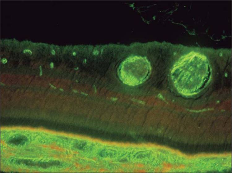
In a normal eye, the retinal blood vessels and the retinal pigment epithelium (RPE) both act as barriers to fluorescein leakage within the retina (Fig. 128.5). The tight junctions of the endothelial cells in normal retinal capillaries make them impermeable to fluorescein leakage. The tight cellular junctions of the healthy RPE provide an outer blood-retinal barrier preventing the normal choroidal leakage from penetrating the retinal tissues.
|
|
|
|
FIGURE 128.5 Blood-retinal barrier. The inner and outer blood-retinal barriers are demonstrated in this photomicrograph. The fluorescein is retained within the retinal vessels by the endothelial cell tight junctions and the choriocapillaris by the RPE. |
Additional anatomical features contribute to the interpretation of the fluorescein angiogram. The choriocapillaris is the capillary-rich layer of the choroid characterized by fenestrated capillary walls that leak fluorescein dye freely into the extravascular space within the choroid. In the posterior fundus, the choriocapillaris is arranged in a mosaic of lobules that accounts for the patchy choroidal fluorescence often seen in the early phases of the angiogram (Fig. 128.6). The taller, more pigmented retinal pigment epithelial cells along with the presence of xanthophyll pigment and absence of retinal capillaries in the center of the fovea (foveal avascular zone) contribute to the relative hypofluorescence of the center of the macula (Fig. 128.7).
|
|
|
|
FIGURE 128.6 Patchy choroidal filling. In the posterior fundus, the choriocapillaris is arranged in a mosaic of lobules that contributes to the patchy choroidal fluorescence often seen in the early phases of the angiogram. |
|
|
|
|
FIGURE 128.7 Normal macular anatomy. The central 500 ?m of the fovea is devoid of blood vessels (foveal avascular zone or FAZ). This fiding, along with the presence of xanthophyll pigment and taller, more pigmented retinal pigment epithelial cells, contributes to the relative hypofluorescence of the macula. |
Early Phase
The early phase of the angiogram can be divided into distinct circulation phases that are useful for interpreting the results (Fig. 128.8a-d).
|
|
|
|
FIGURE 128.8 Normal fluorescein angiogram. (a) Choroidal flush. Fluorescein dye appears first in the choroid, 1-2 s before the dye reaches the retinal arterial circulation. When present, cilioretinal arteries fill along with the choroidal flush since both are supplied by the short posterior ciliary arteries. (b) Arterial phase. The arterial phase occurs when the fluorescein dye enters the retinal arteries. The normal 'arm-to-retina' circulation time is ?12 s. (c) Arteriovenous phase. The arteriovenous phase of the angiogram comprises the time when the retinal arteries, capillaries, and veins contain fluorescein. In the early arteriovenous phase, thin columns of fluorescein are visualized along the walls of the larger veins (laminar flow). (d) Venous phase. As the fluorescein dye begins to exit from the retinal arteries and capillaries, the concentration of fluorescein within the veins increases, resulting in a decrease in fluorescence of the arteries and an increase of fluorescence of the veins. (e) Mid phase. The recirculation phase occurs ?2-4 min after injection. The veins and arteries remain roughly equal in brightness. The intensity of fluorescence diminishes slowly during this phase as fluorescein is removed from the bloodstream by the kidneys. (f) Late phase. The late phase of the angiogram demonstrates the gradual elimination of dye from the retinal and choroidal vasculature. Staining of the optic disk is a normal fiding. Any other areas of late hyperfluorescence suggest the presence of an abnormality, usually the result of fluorescein leakage. |
Choroidal flush
In a normal patient, the dye appears first in the choroid ?10s following injection. The major choroidal vessels are impermeable to fluorescein, but the choriocapillaris leaks fluorescein dye freely into the extravascular space. There is usually little detail in the choroidal flush as the RPE acts as an irregular filter that partially obscures the view of the choroid. If a cilioretinal artery is present, this fills along with the choroidal flush as both are supplied by the short posterior ciliary arteries.
Arterial phase
The retinal arterioles typically fill one to 2 s after the choroid; therefore, the normal 'arm-to-retina' circulation time is ?12s. A delay in the arm-to-retina time may reflect a problem with the fluorescein dye injection or circulatory problems with the patient including heart and peripheral vascular disease.
Arteriovenous phase
Complete filling of the retinal capillary bed follows the arterial phase and the retinal veins begin to fill. In the early arteriovenous phase, thin columns of fluorescein are visualized along the walls of the larger veins (laminar flow). These columns become wider as the entire lumen fills with dye.
Venous phase
Complete filling of the veins occurs over the next 10s with maximum vessel fluorescence occurring ?30s after injection. The perifoveal capillary network is best visualized in the peak venous phase of the angiogram.
Mid Phase
Also known as the recirculation phase, this occurs ?2-4 min after injection. The veins and arteries remain roughly equal in brightness. The intensity of fluorescence diminishes slowly during this phase as much of the fluorescein is removed from the bloodstream on the first pass through the kidneys (see Fig. 128.8e).
Late Phase
The late or elimination phase demonstrates the gradual elimination of dye from the retinal and choroidal vasculature (see Fig. 128.8f). Photographs are typically captured 7-15 min after injection. Late staining of the optic disk is a normal fiding. Any other areas of late hyperfluorescence suggest the presence of an abnormality.
THE ABNORMAL ANGIOGRAM
In evaluating diseases of the macula, fluorescein angiography is helpful in detecting abnormalities in blood flow, vascular permeability, the retinal and choroidal vascular patterns, the RPE, and a variety of other changes.[68] Interpretation of the abnormal angiogram relies on the identification of areas that exhibit hypofluorescence or hyperfluorescence. These are descriptive terms that refer to the time specific, relative brightness of fluorescence in comparison with a normal study (Table 128.4).
TABLE 128.4 -- Abnormal Angiographic Findings
|
Hypofluorescence |
|
Filling defect |
|
Blocking defect |
|
Hyperfluoresence |
|
Autofluorescence |
|
Pseudofluorescence |
|
Transmission or 'window' defect |
|
Leakage |
|
Pooling |
|
Staining |
Hypofluorescence
|
Key Features |
|
Hypofluorescence is usually caused by the blockage of normal fluorescence or abnormal vascular perfusion. |
Pseudofluorescence is the reduction or absence of normal fluorescence. Hypofluorescence is caused by either blockage of the normal fluorescence pattern or abnormalities in choroidal or retinal vascular perfusion.
Blocked fluorescence
Blocked fluorescence is most commonly caused by blood but can result from the deposition of abnormal materials such as lipid exudate, lipofuscin, xanthophyll pigment, or melanin pigment. Fluorescein angiography is very helpful in determining the anatomic location of the blocking material, which in turn, is important in identifying the etiology of the abnormality. For example, preretinal hemorrhage from proliferative diabetic retinopathy blocks visibility of both the retinal and choroidal vasculature while subretinal blood from exudative age-related macular degeneration obscures only the choroidal circulation (Fig. 128.9).
|
|
|
|
FIGURE 128.9 Hypofluorescence: blockage. (a) This fluorescein angiogram of an eye with a central retinal vein occlusion demonstrates widespread hypofluorescence resulting from intraretinal hemorrhages. The majority of hemorrhages are located in the nerve fiber layer, which accounts for the 'flame-shaped' pattern of hypofluorescence along the major vascular arcades. (b) Hypofluorescence related to subretinal hemorrhage is demonstrated in this patient with a ruptured retinal arterial macroaneurysm. The ability to visualize the retinal circulation overlying the blocking defect confirms the subretinal location of the hemorrhage. |
Abnormal vascular perfusion
Abnormal vascular perfusion results in hypofluorescence of the retinal and/or choroidal circulation depending on the location of the abnormality. Common causes of retinal hypoperfusion include retinal arterial and venous occlusions and ischemic disease due to diabetes and other causes. Choroidal hypoperfusion may be produced by ophthalmic artery occlusion, giant cell arteritis, and hypertensive choroidopathy. It is important to understand the relationship between hypofluorescence due to filling defects and the specific phase of the angiogram. For example, in many vascular occlusions the hypofluorescence may be a temporary fiding until delayed filling of the affected vessel occurs in the later phases of the study (Fig. 128.10).
|
|
|
|
FIGURE 128.10 Hypofluorescence: nonperfusion. (a) In this patient with advanced diabetic retinopathy, there is marked hypofluorescence throughout the retina as a result of widespread ischemia. Note that there are scattered patches of more prominent hypofluorescence from intraretinal hemorrhages. (b) This patient with diabetic macular edema has significant macular ischemia with capillary dropout and enlargement and irregularity of the foveal avascular zone. Contrast this with the normal perifoveal capillary network shown in Figure 128.7. |
Hyperfluorescence
|
Key Features |
|
Hyperfluorescence usually results from atrophy of the pigment epithelium (transmission or 'window' defect) or leakage of fluorescein dye. |
Hyperfluorescence is an increase in fluorescence resulting from the increased transmission of normal fluorescence or an abnormal presence of fluorescein at a given time in the angiogram.
Autofluorescence and pseudofluorescence are terms to describe the appearance of apparent hyperfluorescence in the absence of fluorescein.
Autofluorescence
Autofluorescence refers to recordable hyperfluorescence that is believed to occur naturally in certain pathologic entities such as optic nerve drusen and astrocytic hamartomas. Some, but not all disk drusen appear to fluoresce under blue light (Fig. 128.11). Some controversy exists over whether this is actual fluorescence or reflectance.[69] These structures are highly reflective in the same spectral range of fluorescence and could actually be exhibiting pseudofluorescence.
|
|
|
|
FIGURE 128.11 Hyperfluorescence: autofluorescence. (a) Red-free photograph of a patient with disk drusen. (b) A photograph taken with fluorescein exciter and barrier filters demonstrates autofluorescence of the disk drusen in the absence of fluorescein. |
Pseudofluorescence
Pseudofluorescence occurs as a result of crossover in the spectral transmission curves of the exciter and barrier filters. If too much crossover is present, reflectance from bright fundus structures will not be fully blocked by the barrier filter. Crossover can be the result of mismatched or aging filters. Modern interference filters rarely exhibit significant crossover unless they have deteriorated. Control photographs are routinely taken before injection of fluorescein to detect the possible presence of pseudofluorescence.
Transmission defect
Depending on the density of retinal pigmentation, background fluorescence from the choroid can be visible as hyperfluorescence in the angiogram. A 'window defect' is an area of hyperfluorescence that occurs when there is an absence or reduction of pigmentation due to damage of the RPE. The loss of pigment allows visualization of the fluorescence created by the underlying choriocapillaris (Fig. 128.12). Window defects remain uniform in size throughout the angiogram. Their brightness rises and falls with the choroidal fluorescence. It is important to differentiate hyperfluorescence due to transmission defects from leakage.
|
|
|
|
FIGURE 128.12 Hyperfluorescence: transmission defect. A transmission or 'window' defect is seen in this patient with age-related macular degeneration with geographic atrophy. Atrophy of the RPE allows visualization of the underlying choroidal fluorescence. The hyperfluorescence usually appears early in the angiogram and is not associated with leakage in the late phase. |
Leakage
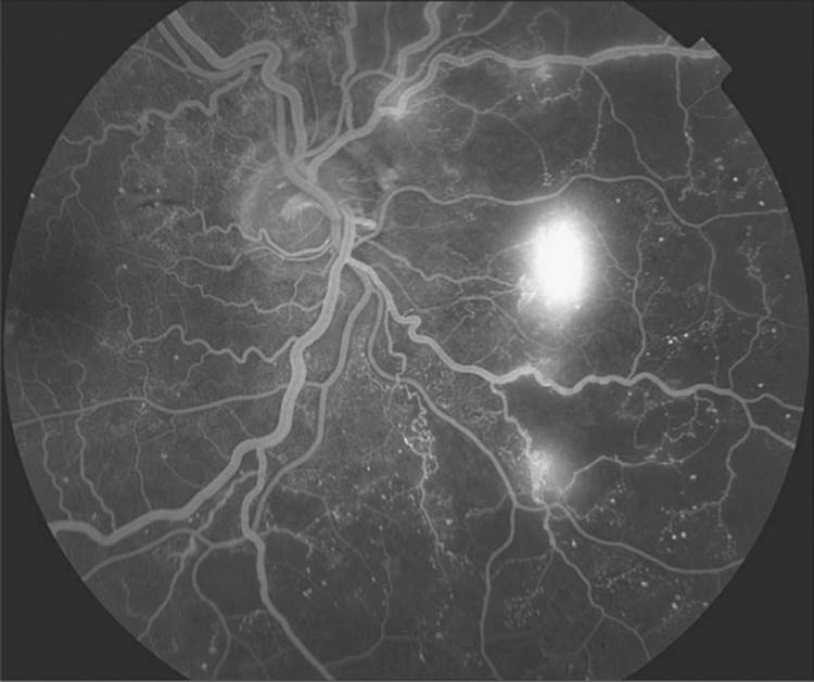
Leakage refers to hyperfluorescence in the angiogram due to extravasation of fluorescein dye. Leakage can result from disruption of the retinal vascular endothelial cell tight junctions or the breakdown of the tight junctions between retinal pigment epithelial cells (the inner and outer blood-retinal barriers, respectively). Examples include macular edema from diabetic retinopathy (Fig. 128.13), cystoid macular edema, and central serous chorioretinopathy. In addition to abnormalities of the retinal vascular system or pigment epithelium, leakage is observed in a variety of conditions associated with the development of new blood vessels. For example, fluorescein leakage is seen in eyes with choroidal neovascularization related to age-related macular degeneration. In these patients, fluorescein angiography is needed to identify the location and features of the choroidal neovascular membrane which, in turn, influences the course of treatment (Fig. 128.14). In eyes with proliferative diabetic retinopathy, optic disk or retinal neovascularization is characterized by intense fluorescein leakage (Fig. 128.15). Leakage can lead to late staining or pooling of dye.
|
|
|
|
FIGURE 128.13 Hyperfluorescence: leakage. The phenomenon of hyperfluorescence related to fluorescein leakage is demonstrated in this patient with diabetic retinopathy. (a) The arteriovenous phase image reveals multiple hyperfluorescent spots corresponding to microaneurysms. (b) In the late phase angiogram, there is diffuse hyperfluorescence related to leakage from the microaneurysms and irregular capillaries. |
|
|
|
|
FIGURE 128.14 Hyperfluorescence: leakage. This pair of images demonstrates fluorescein leakage from exudative age-related macular degeneration. (a) During the arteriovenous phase, the abnormal choroidal blood vessels become visible (they are surrounded by a zone of hypofluorescence caused by the blocking effect of hemorrhage). (b) In the late phase angiogram, there is significant leakage of fluorescein throughout the macula. |
|
|
|
|
FIGURE 128.15 Hyperfluorescence: leakage. Retinal neovascularization is characterized by profuse leakage on fluorescein angiography. The areas of retinal neovascularization usually are located at the junction of the perfused and nonperfused retina. |
Staining
Staining refers to late hyperfluorescence resulting from the accumulation of fluorescein dye into certain tissues. Drusen and chorioretinal scars commonly exhibit staining. Normal staining can occur in the optic nerve and sclera as a result of normal choroidal leakage. Scleral staining is usually only visible when there is a reduction or absence of the pigment epithelium (window defect) and the sclera can be seen clinically (Fig. 128.16).
|
|
|
|
FIGURE 128.16 Hyperfluorescence: staining. This late phase angiogram demonstrates staining of drusen. Hyperfluorescence is observed as fluorescein accumulates within the drusen material. |
Pooling
Pooling is the accumulation of dye within a distinct anatomic space. Pooling can occur in serous detachments of the sensory retina or the RPE due to a breakdown of the blood-retinal barrier. Central serous chorioretinopathy is a condition that often demonstrates the pooling of fluorescein (Fig. 128.17).
|
|
|
|
FIGURE 128.17 Hyperfluorescence: pooling. This pair of angiographic images demonstrates the phenomenon of pooling. (a) Central serous chorioretinopathy is characterized by a hyperfluorescent spot that increases in size and intensity throughout the study. (b) Ten minutes after injection, this patient has the characteristic 'smokestack' appearance as fluorescein accumulates or 'pools' within the localized neurosensory retinal detachment. |
COMPLEMENTARY IMAGING TECHNIQUES
Fluorescein angiography continues to be a vital tool in the detection of retinal vascular disorders. A number of additional diagnostic imaging procedures serve as an adjunct to angiography. Some have a long history of complementary use with fluorescein angiography, while newer techniques can add new diagnostic insights and value to the 'Gold Standard' of retinal imaging. Color stereo fundus photography is a natural complement to fluorescein angiography and has traditionally been included in standard angiography protocols along with monochromatic green light 'red free' photographs. Monochromatic fundus photography with other colors of light has been used for decades, but is probably underutilized given its inherent value. More recently, ICG angiography, OCT, and FAF have expanded the available arsenal of diagnostic imaging procedures.
ICG ANGIOGRAPHY
Digital technology facilitates the use of another fluorescent dye, ICG, for retinal and choroidal angiography. With peak absorption (805nm) and emission (835nm) in the near-infrared range, ICG provides greater transmission through the RPE and hemorrhage than the visible wavelengths used in fluorescein angiography. ICG also binds more completely with blood albumins, so it normally remains within the fenestrated walls of the choriocapillaris, unlike fluorescein, which leaks freely from these vessels.
ICG choroidal angiography was first performed in humans in 1972, but results were limited by insufficient sensitivity of available infrared films.[70] In the early 1990s, two groups reported improved results with commercially available digital angiography systems.[71,72] The infrared sensitivity of available CCD cameras was combined with new lens coatings applied to fundus camera optics to improve infrared transmission for ICG angiography. In the early to mid 1990s, enthusiasm for this procedure exceeded its practical applications. Use of this technique waned by the late 1990s as clinical research had defied a vital, but limited role for ICG angiography as an adjunct to fluorescein angiography.
Today, ICG angiography is used in combination with fluorescein angiography in a limited number of diagnoses where choroidal circulation is effected, particularly in patients with age-related macular degeneration.[73] The goal in age-related macular degeneration is to identify localized areas of choroidal neovascularization or choroidal feeder vessels that can be treated with a laser to prevent damage to the retina.[74-76]
MONOCHROMATIC FUNDUS PHOTOGRAPHY
Monochromatic fundus photography is the practice of imaging the ocular fundus with the use of colored or monochromatic illumination. In 1925, Vogt described the use of green light to enhance the visual contrast of anatomical details of the fundus.[77] The technique is still commonly used today in combination with fundus photography. Monochromatic fundus photography is based on increased scattering of light at shorter wavelengths and the use of contrast filters to alter subject tones in black and white photographs. By limiting the spectral range of the illuminating source, the visibility of various fundus structures can be enhanced (Fig. 128.18).[78-81] This technique is most effective when combined with high-resolution black-and-white film or digital sensors.
|
|
|
|
FIGURE 128.18 Monochromatic Imaging. (a) Fluorescein angiogram of a choroidal lesion. (b) Mononchromatic red light (peak transmission at 615 nm) imaging is particularly useful for documenting lesions deep within the retina and choroid. Longer wavelengths partially penetrate the retina pigment epithelium and make it appear more transparent, revealing the borders of the nevus. |
Blue light increases visibility of the anterior retinal layers, which normally are almost transparent in white light. Blue light is absorbed by retinal pigmentation and blood vessels, providing a dark background against which the specular reflections and scattering in the anterior layers of the fundus is enhanced. Scattering in the ocular media can limit the effectiveness of these wavelengths. The retinal nerve fiber layer, the internal limiting membrane, retinal folds, cysts and epiretinal membranes are examples of semitransparent scattering structures that are enhanced with short wavelength illumination. Because of excessive scattering at very short wavelengths, fluorescein exciter filters at blue-green wavelengths of 490nm are often used.
Green light is also absorbed by blood, but is reflected more than blue light by retinal pigmentation. There is less scatter than with shorter wavelengths, so media opacities are not quite as troublesome. Green light provides excellent contrast and the best overall view of the fundus. It enhances the visibility of the retinal vasculature, and common fidings such as hemorrhages, drusen and exudates. For this reason, green filter 'red-free' photos are routinely taken as baseline images before fluorescein angiography.
Retinal pigmentation appears more transparent in red light, revealing the choroidal pattern. Overall fundus contrast is greatly reduced with red illumination. Retinal vessels appear lighter and become less obvious at longer wavelengths. The optic nerve appears lighter and almost featureless. Red light is useful for imaging pigmentary disturbances, choroidal ruptures, choroidal nevi, and choroidal melanomas.
Traditionally, monochromatic photography has required use of high-resolution black-and-white films and customized film processing techniques to maximize diagnostic information. These film and developer combinations could be difficult to control, which may explain why monochromatic photography never gained universal acceptance. Digital imaging facilitates immediate control of exposure settings and easy contrast enhancement, making the monochromatic technique more practical for widespread use.
OPTICAL COHERENCE TOMOGRAPHY
OCT is useful in the diagnosis of several retinal disorders that have traditionally been imaged with fundus photography or fluorescein angiography. OCT imaging provides direct cross-sectional images of the macula, retinal nerve fiber layer and optic nerve for objective measurement and clinical evaluation in the detection of retinal diseases and glaucoma. It is particularly useful in the detection of changes in normal retinal architecture such as macular holes, epiretinal membranes, vitreomacular traction, cystoid macular edema, subretinal fluid, and retinal pigment epithelial detachments.[82,83] Its greatest value however, may lie in the ability to quantify and monitor change in retinal thickness due to macular edema from diabetic retinopathy or other causes.
Although the technology has been available since 1991, OCT was mostly used in academic settings or for research applications until 2002, when the evolution of the instrumentation, in the form of increased resolution and ease of operation, matured to the point where OCT imaging became both practical and affordable. Since its introduction, OCT has rapidly gained widespread acceptance and for certain retinal conditions, is now the diagnostic procedure of choice. Compared to angiography, OCT is less expensive, noninvasive, faster, well tolerated and easy to perform. The procedure can be conducted in ?10 min, usually without dilation or discomfort to the patient. Enthusiasm for OCT continues to grow as new instruments are being developed by a number of manufacturers. Advances in technology that use spectral or Fourier domain OCT techniques, promise improvement in resolution and acquisition speed, as well as 3-D viewing of retinal structures.
Fluorescein angiography was originally developed to look specifically at retinal blood flow. An unexpected benefit was the ability to detect structural changes in certain retinal conditions by observation of fluorescein staining patterns in abnormal retinal tissues or anatomic spaces caused by structural change. OCT has demonstrated great application in detecting many of these structural abnormalities and fluorescein angiography is no longer needed for some of these diagnoses (Fig. 128.19). The true strength of angiography lies in its original purpose, to look specifically at flow dynamics in the retinal and choroidal vasculature. Used in tandem, OCT and fluorescein angiography provide a wealth of diagnostic information to aid in the management of retinal disease (Fig. 128.20).
|
|
|
|
FIGURE 128.19 Optical coherence tomography. OCT imaging can be used as an adjunct to, or a replacement for, fluorescein angiography. OCT imaging has become the diagnostic procedure of choice to detect cystoid macular edema, a condition that was traditionally confirmed with fluorescein angiography. |
|
|
|
|
FIGURE 128.20 Optical coherence tomography. The combination of fluorescein angiography and OCT can provide the clinician with greater diagnostic information as demonstrated in this case of idiopathic central serous chorioretinopathy. Angiography identifies the area of active leakage, while OCT illustrates a compartmentalized serous detachment. |
FUNDUS AUTOFLUORESCENCE
FAF is a recently developed noninvasive imaging technique for documenting the presence of lipofuscin in the RPE. Lipofuscin is a fluorescent pigment that accumulates in the RPE as a result of incomplete degradation of photoreceptor outer segments as the eye ages. When excited with short wavelength illumination, lipofuscin granules autofluoresce, exhibiting a broad emission spectrum from 500 to 750nm with peak emission at ?630nm.[84]
The original technique used a confocal SLO with the excitation wavelength set at 488nm and a wide band-pass filter with short wavelength cutoff at 521nm.[85] Several frames are captured with the SLO, then aligned and averaged to reduce noise. Because several frames are required, image quality may be affected by eye movement during capture. More recently, digital fundus-camera based systems have been developed which use high-sensitivity monochrome sensors with an excitation filter at 580nm and a barrier filter at 695nm to avoid confounding autofluorescence from the crystalline lens.[86] Both systems require significant amounts of light and increased gain settings to achieve adequate exposure, and are subject to image noise. Despite the disparity in excitation wavelength and barrier filters between the SLO and fundus camera systems, these two techniques obtain results that are quite similar in appearance.
Autofluorescence imaging has the potential to provide useful information in conditions where the health of the RPE plays a key role. Hyperfluorescence is a sign of increased lipofuscin accumulation, which may indicate degenerative changes or oxidative injury. Areas of hypofluorescence indicate missing or dead RPE cells. Geographic atrophy that appears as a window defect in fluorescein angiography will appear dark in autofluorescent imaging (Fig. 128.21). A number of investigators have been exploring potential applications of this imaging technique in a variety of retinal diseases including: retinitis pigmentosa,[87] central serous chorioretinopathy,[88] macular dystrophies,[89] pseudoxanthoma elasticum,[90] and age-related macular degeneration.[86] The role of lipofuscin in the pathogenesis of macular degeneration is currently unknown, but increased autofluorescence may precede development or progression of geographic atrophy in AMD.[91]
|
|
|
|
FIGURE 128.21 Fundus autofluorescence. (a) Fluorescein angiography image of a patient with geographic atrophy in age-related macular degeneration. (b) Fundus autofluorescent imaging (excitation at 580 nm and barrier at 695nm) noninvasively identifies RPE atrophy as areas of hypofluorescence due to an absence or reduction of lipofuscin accumulation. |
SUMMARY
Fluorescein angiography has revolutionized the understanding, diagnosis and treatment of retinal vascular disorders. For over 40 years, ophthalmologists have used fluorescein angiography as a guide for laser treatment, benefiting many thousands of patients. This important diagnostic tool continues to evolve with new advances in digital imaging technique. As new treatment modalities are developed, fluorescein angiography will continue to play an important role in the management of retinal conditions.
REFERENCES
1. Wolfe DR: Fluorescein angiography basic science and engineering. Ophthalmology 1986; 93:1617-1620.
2. Morris PF: Fluorescein sodium and indocyanine green: uses and side effects. In: Saine PJ, Tyler ME, ed. Ophthalmic photography: retinal photography, angiography and electronic imaging, 2nd edn. Boston: Butterworth-Heinemann; 2002:137-165.
3. Jacobs J: Fluorescein sodium - what is it?. J Ophthal Photography 1992; 14:62.
4. Dole RB: Use of fluorescein in the study of underground waters. USGS Water Supply Paper 1906; 160:73-85.
5. Myers B: Prediction of skin sloughs at the time of operation with the use of fluorescein dye. Surgery 1962; 51:158-162.
6. McCaw JB, Myers B, Shanklin KD: The value of fluorescein in predicting the viability of arterialized flaps. Plast Reconstr Surg 1977; 60:710-719.
7. Singer R, Lewis CM, Franklin JD, et al: Fluorescein test for prediction of flap viability during breast reconstructions. Plast Reconstr Surg 1978; 61:371-375.
8. Smith Jr JA, Middleton RG: The use of fluorescein in radical inguinal lymphadenectomy. J Urol 1979; 122:754-756.
9. Sloan GM, Sasaki GH: Noninvasive monitoring of tissue viability. Clin Plast Surg 1985; 12:185-195.
10. Stolar CJ, Randolph JG: Evaluation of ischemic bowel viability with a fluorescent technique. J Pediatr Surg 1978; 13:221-225.
11. Marfuggi R, Greenspan M: Intraoperative prediction of intestinal viability. Surg Gynae Obstet 1981; 152:33-35.
12. Crimson J, Fuhrman F: Studies on gangrene following cold injury. IV. The use of fluorescein as an indicator of local blood flow: fluorescein test in experimental frostbite. J Clin Invest 1947; 26:259-268.
13. Gatti JE, LaRossa D, Silverman DG, et al: Evaluation of the burn wound with perfusion fluorometry. J Trauma 1983; 23:202-206.
14. Minor DR, Allen RE, Alberts D, et al: A clinical and pharmacokinetic study of isolated limb perfusion with heat and melphalan for melanoma. Cancer 1985; 55:2638-2644.
15. Martonyi CL, Bahn CF, Meyer RF: Clinical slit lamp biomicroscopy and photo slit lamp biomicrography, Ann Arbor, MI: Time One Ink; 1985:64-67.
16. Saine PJ: Landmarks in the development of fluorescein angiography. J Ophthal Photography 1993; 15:17-23.
17. Chao P, Flocks M: The retinal circulation time. Am J Ophthalmol 1958; 46:8-10.
18. Flocks M, Miller J, Chao P: Retinal circulation time with the aid of fundus cinematography. Am J Ophthalmol 1959; 48:3-6.
19. MacLean AL, Maumenee AE: Hemangioma of the choroid. Am J Ophthalmol 1960; 50:2-11.
20. Novotny HR, Alvis DL: A method of photographing fluorescence in circulating blood of the human retina. Circulation 1961; 24:82-86.
21. David NJ, Justice J: The early days of fluorescein angiography. J Ophthal Photography 1994; 16:83-86.
22. Quillen DA, Gardner TW, Blankenship GW: The Diabetic Retinopathy Study. In: Kertes PJ, Conway MD, ed. Clinical trials in ophthalmology: a summary and practice guide, Baltimore: Williams & Wilkins; 1998:1-13.
23. Physicians' desk reference for ophthalmic medicines, Montvale: Thompson PDR; 2006:207.
24. Palestine AG: Does intravenous fluorescein interfere with clinical laboratory testing. J Ophthal Photography 1991; 13:27-28.
25. Bloom JN, Herman DC, Elin RJ, et al: Intravenous fluorescein interference with clinical laboratory tests. Am J Ophthalmol 1989; 108:375-379.
26. Mattern J, Mayer PR: Excretion of fluorescein into breast milk [letter]. Am J Ophthalmol 1990; 109:598.
27. AK-FLUOR package insert, rev 08/05. Akorn, Inc Buffalo Grove, IL. Available: http://www.akorn.com/documents/catalog/package_inserts/17478-254-10.pdf
28. Halperin LS, Olk RJ, Soubrane G, et al: Safety of fluorescein angiography during pregnancy. Am J Ophthalmol 1990; 109:563-566.
29. Greenberg F, Lewis RA: Safety of fluorescein angiography during pregnancy [letter]. Am J Ophthalmol 1991; 110:323-325.
30. Berkow JW, Flower RW, Orth DH, Kelley JS: Fluorescein and indocyanine green angiography, 2nd edn. San Francisco: American Academy of Ophthalmology; 1997:7.
31. Chazan BI, Balodimos MC, Koncz L: Untoward effects of fluorescein retinal angiography in diabetic patients. Ann Ophthalmol 1971; 3:42.
32. Pacirariu RI: Low incidence of side effects following intravenous fluorescein angiography. Ann Ophthalmol 1982; 14:32-36.
33. Butner RW, McPherson AR: Adverse reactions in intravenous fluorescein angiography. Ann Ophthalmol 1983; 15:1084-1086.
34. Marcus DF, Bovino JA, Williams D: Adverse reactions during intravenous fluorescein angiography. Arch Ophthalmol 1984; 102:825.
35. Yannuzzi LA, Rohrer KT, Tindel LJ, et al: Fluorescein angiography complication survey. Ophthalmology 1986; 93:611-617.
36. Karhunen U, Raitta C, Kala R: Adverse reactions to fluorescein angiography. Acta Ophthalmol 1986; 64:282-286.
37. Kwiterovitch KA, Maguire MG, Murphy RP, et al: Frequency of adverse systemic reactions occurring after fluorescein angiography - results of a prospective study. Ophthalmology 1991; 98:1139-1142.
38. Kwan AS, Barry CJ, McAllister IL, et al: Fluorescein angiography and adverse drug reactions revisited: the Lions Eye experience. Clin Exp Ophthalmol 2006; 34:33-38.
39. Eutick M: Sodium fluorescein - colourful past, bright future. J Ophthal Photography 2006; 28:66-70.
40. Ellis PP, Schoenberger M, Rendi MA: Antihistamines as prophylaxis against side reactions to intravenous fluorescein. Trans Am Ophthalmol Soc 1980; 78:190-205.
41. Buchanan RT, Levine NS: Blood pressure drop as a result of fluorescein injection. Plast Reconstr Surg 1982; 70:363-368.
42. Merin LM, Lam BL: Case report: fluorescein angiogram during vasovagal syncope. J Ophthal Photography 1994; 16:94-95.
43. Gombos GM, Lieberman RM: Seizures associated with fluorescein angiography. Ann Ophthalmol 1989; 21:89-90.
44. Kelly SP, Mcdermott NJ, Saunders DC, et al: Convulsion following fluorescein angiography. Br J Ophthalmol 1989; 73:655-656.
45. Hess JB, Pacirariu RI: Acute pulmonary edema following intravenous fluorescein angiography. Am J Ophthalmol 1976; 82:567-570.
46. Deglin SM, Deglin EA, Chung EK: Acute myocardial infarction following fluorescein angiography. Heart Lung 1977; 6:505-509.
47. Acasco FJ, Tiestos MT, Navales J, et al: Fatal acute myocardial infarction after intravenous fluorescein angiography. Retina 1993; 13:238-239.
48. Schatz H: Sloughing of skin following fluorescein extravasation. Ann Ophthalmol 1978; 10:625.
49. Elman MJ, Fine SL, Sorenson J, et al: Skin necrosis following fluorescein extravasation. A survey of the Macula Society. Retina 1987; 7:89-93.
50. Lipson BK, Yannuzzi LA: Complications of fluorescein injections. Int Ophthalmol Clin 1989; 29:200-205.
51. Kelley JS, Kincaid M: Retinal fluorography using oral fluorescein. Arch Ophthalmol 1979; 97:2331-2332.
52. Hara T, Inami M, Hara T: Ef-cacy and safety of fluorescein angiography with orally administered sodium fluorescein. Am J Ophthalmol 1998; 126:560-564.
53. Kinsella FP, Mooney DJ: Anaphylaxis following oral fluorescein angiography. Am J Ophthalmol 1988; 106:745-746.
54. Gomez-Ulla F, Gutierrez C, Seonae I: Severe anaphylactic reaction to orally administered fluorescein. Am J Ophthalmol 1991; 112:94.
55. In: Saine PJ, Tyler ME, ed. Ophthalmic photography: retinal photography, angiography and electronic imaging, 2nd edn. Boston: Butterworth-Heinemann; 2002:247-248.
56. Oosterwijk H: DICOM versus HL7 for modality interfacing. J Digit Imaging 1998; 11(3 Suppl 1):39-41.
57. Kabachinski J: DICOM: key concepts-part I. Biomed Instrumen Technol 2005; 39:214-216.
58. Kabachinski J: DICOM: key concepts-part II. Biomed Instrumen Technol 2005; 39:292-294.
59. Bidgood Jr WD, Horii SC: Introduction to the ACR-NEMA DICOM standard. Radiographics 1992; 12:345-355.
60. Bennett TJ, MacGregor G, Scheuneman JD: Digital Imaging and the certi-ed retinal Angiographer Program. J Ophthal Photography 2004; 26:28-36.
61. Benetz BA, Bennett TJ, Tomer TL: What does today's ophthalmic photographer do. J Ophthal Photography 2005; 27:85-87.
62. Woon WH, Fitzke FW, Chester GH, et al: The scanning laser ophthalmoscope: basic principles and applications. J Ophthal Photography 1990; 12:17-23.
63. Clark TM: Scanning laser ophthalmoscopes. In: Saine PJ, Tyler ME, ed. Ophthalmic photography: retinal photography, angiography and electronic imaging, 2nd edn. Boston: Butterworth-Heinemann; 2002:306-321.
64. Allen L: Ocular fundus photography: suggestions for achieving consistently good pictures and instructions for stereoscopic photography. Am J Ophthalmol 1964; 57:13-28.
65. Bennett TJ: Stereo anaglyph preparation for PowerPoint. J Ophthal Photography 2005; 27:38-45.
66. Ellis JH, Weber P: Legal issues arise when unlicensed personnel administer IV fluorescein. Argus 1995; Nov-Dec:28-31.
67. Ophthalmic photographers' society standards of practice. J Ophthal Photography 1999; 21:26.
68. Gass JDM: Stereoscopic atlas of macular diseases: diagnosis and treatment, 4th edn. St Louis, Mosby, 1997.
69. Barry C, Singh J, Constable IJ: Are optic disc drusen exhibiting Autofluorescence, pseudofluorescence or reflectance. J Ophthal Photography 2000; 22:32-35.
70. Flower RW, Hochheimer BF: Clinical infrared absorption angiography of the choroids. Am J Ophthalmol 1972; 73:458-459.
71. Guyer DR, Pulia-to CP, Mones JM, et al: Digital indocyanine-green angiography in chorioretinal disorders. Ophthalmology 1992; 99:287-290.
72. Yannuzzi LA, Slakter JS, Sorenson JA, et al: Digital indocyanine green videoangiography and choroidal neovascularization. Retina 1992; 12:191-223.
73. Stanga PE, Lim JI, Hamilton P: Indocyanine green angiography in chorioretinal diseases: indications and interpretation: an evidence-based update. Ophthalmology 2003; 110:15-21.
74. Shiraga F, Ojima Y, Matsuo T, et al: Feeder vessel photocoagulation of subfoveal choroidal neovascularization secondary to age-related macular degeneration. Ophthalmology 1998; 105:662-691.
75. Flower RW: Experimental studies of indocyanine green dye-enhanced photocoagulation of choroidal neovascularization feeder vessels. Am J Ophthalmol 2000; 129:501-512.
76. Flower RW: Optimizing treatment of choroidal neovascularization feeder vessels associated with age-related macular degeneration. Am J Ophthalmol 2002; 134:228-239.
77. Vogt A: Die Ophthalmoskopie im rotfreiem licht. GraefSaemisch Handbuch der gesamten Augenheilkunde, Berlin, Springer Verlag, 1925.
78. Delori FC, Gragoudas ES: Examination of the ocular fundus with monochromatic light. Ann Ophthalmol 1976; 8:703-709.
79. Behrendt T, Slipakoff E: Spectral reflectance photography. Int Ophthalmol Clin 1976; 16:95-100.
80. Delori FC, Gragoudas ES, Francisco R, et al: Monochromatic ophthalmoscopy and fundus photography. The normal fundus. Arch Ophthalmol 1977; 95:861-868.
81. Ducrey NM, Delori FC, Gragoudas ES: Monochromatic ophthalmoscopy and fundus photography. II. The pathological fundus. Arch Ophthalmol 1979; 97:288-293.
82. Pulia-to CA, Hee MR, Lin CP, et al: Imaging of macular diseases with optical coherence tomography. Ophthalmology 1995; 102:217-229.
83. Costa RA, Skaf M, Melo Jr LA, et al: Retinal assessment using optical coherence tomography. Prog Retin Eye Res 2006; 25:325-353.
84. Delori FC, Dorey CK, Staurenghi G, et al: In vivo fluorescence of the ocular fundus exhibits retinal pigment epithelium lipofuscin characteristics. Invest Ophthalmol Vis Sci 1995; 36:718-729.
85. von Ruckman A, Fitzke FW, Bird AC: Distribution of fundus autofluorescence with a scanning laser ophthalmoscope. Br J Ophthalmol 1995; 79:407-412.
86. Spaide RF: Fundus autofluorescence and age-related macular degeneration. Ophthalmology 2003; 110:392-399.
87. Robson AG, Egan C, Holder GE, et al: Comparing rod and cone function with fundus autofluorescence images in retinitis pigmentosa. Adv Exp Med Biol 2003; 533:41-47.
88. Spaide RF, Klancnik Jr JM: Fundus autofluorescence and central serous chorioretinopathy. Ophthalmology 2005; 112:825-833.
89. Von Ruckmann A, Fitzke FW, Bird AC: In vivo fundus autofluorescence in macular dystrophies. Arch Ophthalmol 1997; 115:609-615.
90. Sawa M, Ober MD, Freund KB, et al: Fundus autofluorescence in patients with pseudoxanthoma elasticum. Ophthalmology 2006; 113:814-820.
91. Hopkins J, Walsh A, Chakravarthy U: Fundus autofluorescence in age-related macular degeneration: an epiphenomenon. Invest Ophthalmol Vis Sci 2006; 47:2269-2271.