
Daniel J. Sucato
DEFINITION
 Thoracic scoliosis and thoracolumbar–lumbar scoliosis are typically curves seen in idiopathic scoliosis and can be treated anteriorly.
Anterior arthrodesis refers to the fusion of the anterior part of the vertebral bodies, usually with instrumentation for these curve patterns.
ANATOMY
Thoracic idiopathic scoliosis usually has an apex at T8 or T9. It is the most common right convex curve pattern and has axial-plane rotational deformity as well as hypokyphosis.
The vertebral bodies are nearly normal in their shape, although some distortion of the vertebral body and pedicles is seen, with thin long pedicles on the concavity and shorter, wider pedicles on the convexity.
Thoracolumbar–lumbar scoliosis has an apex of the curve at T12 or below and is most commonly a left-sided curve, with or without a compensatory thoracic curve.
PATHOGENESIS
The cause of idiopathic scoliosis is not yet known.
NATURAL HISTORY
Idiopathic scoliosis progresses with continued growth of the spine, especially during the peak growth periods and when the curve magnitudes are “large” at the completion of growth.
Thoracic curves tend to progress at skeletal maturity when the curve is greater than 45 to 50 degrees.
Thoracolumbar–lumbar curves tend to progress when the curve is greater than 35 to 40 degrees at the time of skeletal maturity.
PATIENT HISTORY AND PHYSICAL FINDINGS
Patients with thoracic scoliosis and thoracolumbar scoliosis should be evaluated for their perception of spine and body deformity to include asymmetric shoulder elevation, trunk shift, waistline asymmetry, and rib or flank prominence.
Pain in the axial spine and pain radiating into the lower extremities should be ascertained with a good history; such symptoms warrant an MRI.
Neurologic symptoms such as paresthesias, hyperesthesia, or bowel or bladder symptoms are relevant and require further imaging with an MRI.
Physical examination should assess the trunk imbalance in the coronal plane, which can be seen with isolated thoracic or thoracolumbar–lumbar curves.
The Adams forward bend test characterizes the axial-plane deformity seen in scoliosis and is used to assess rotational deformity of the thoracic rib prominence or the flank prominence. The rotational deformity of the thoracic and lumbar spine is graded using a scoliometer with the patient bending forward. The rotational deformity seen in scoliosis can be very prominent and the most obvious deformity seen by patient and families.
Cutaneous manifestations of dysraphism should also be analyzed.
IMAGING AND OTHER DIAGNOSTIC STUDIES
Anteroposterior (AP) and lateral radiographs of the spine should be obtained to review the coronal and sagittal plane deformities, respectively (FIG 1).
On the AP radiograph, the coronal plane deformity is measured using the Cobb method. Truncal imbalance can be measured using the Floman method (bisecting the distance between the lateral rib margins and comparing this point to the center sacral vertical line [CSVL]).
The decompensation of the head relative to the pelvis is measured by the distance between the C7 plumb line and the CSVL.
The Risser sign should be evaluated by assessing the ossification of the iliac apophysis, giving it a grade between 0 and 5.
The triradiate cartilage status should be assessed as either open or closed.
The lateral radiograph is used to measure thoracic kyphosis (measured from T5 to T12) and lumbar lordosis (from L1 to S1) as well as the sagittal balance (comparing a C7 plumb bob line to the front edge of S1).
Supine best-bend radiographs can be used to determine the flexibility of the spine and are especially useful to determine whether the thoracolumbar–lumbar curve is flexible when a primary thoracic curve is present or if the thoracic curve is flexible and compensatory when the primary thoracolumbar– lumbar curve is present.

FIG 1 • AP and lateral radiographs of a 51-degree left lumbar curve.
DIFFERENTIAL DIAGNOSIS
Idiopathic scoliosis should be differentiated from other types of scoliosis in which congenital abnormalities are not seen in ambulatory patients. This list includes neurofibromatosis, Marfan syndrome, type 3 spinal muscular atrophy, scoliosis associated with syringomyelia, or tethered cord.
NONOPERATIVE MANAGEMENT
Adolescent thoracic and thoracolumbar scoliosis can be treated with bracing when curve magnitudes are between 25 and 45 degrees during peak growth periods.
Bracing is used for these curve magnitudes to prevent curve progression and is indicated in Risser grade 0 to 2 patients.
Nonoperative management is primarily indicated when the cosmetic appearance of the patient is acceptable to him or her.
SURGICAL MANAGEMENT
Surgical indications for thoracic idiopathic scoliosis are curves exceeding 45 to 50 degrees with unacceptable cosmetic deformity.
Indications for surgical treatment of thoracolumbar–lumbar curves are curves exceeding 40 to 45 degrees with unacceptable cosmetic deformity.
Preoperative Planning
A careful physical examination as noted above is necessary to ensure that there are no neurologic signs or symptoms, which would indicate neural axis abnormalities. If these are present, MRI of the neural axis is indicated.
Radiographic imaging should be used to ensure the curve is characteristic of an idiopathic curve. For thoracic curve magnitudes, this should demonstrate apical lordosis. The atypical curves, such as left-sided thoracic curves or those with significant decompensation despite minimal rotational deformity, or patients who have excessive thoracic kyphosis should be further evaluated with an MRI.
The AP radiograph, the lateral standing radiograph, and the supine best-bend radiograph should be used to determine the Lenke classification.
Specific detailed analysis of the compensatory curves should be performed to fine-tune a surgical plan to ensure that postoperative decompensation does not occur. This is especially important to determine the flexibility of the lumbar curve and the lumbar modifier for primary thoracic curves, as well as the flexibility of the compensatory thoracic curve for primary thoracolumbar–lumbar curves.
Anterior fusion levels for thoracic scoliosis are, in general, proximal-end vertebra to distal-end vertebra. Occasionally a parallel disc is noted at the distal segment. It is controversial whether this disc should be included in the fusion levels. When the curve is relatively small (50 to 60 degrees) and flexible (greater than 50% flexibility index) and the patient is skeletally mature (triradiate cartilage is closed and Risser grade 1 or higher), inclusion of the parallel disc is not often necessary (FIG 2A,B).
Anterior fusion levels for thoracolumbar–lumbar curves in general are proximal-end vertebra to distal-end vertebra. When the disc below the planned lowest instrumented vertebra is reversing and opening into the fractional lumbosacral curve, then disc wedging is not seen postoperatively. However, a disc below the lowest instrumented vertebra that is parallel preoperatively will often be wedged postoperatively (FIG 2C,D).
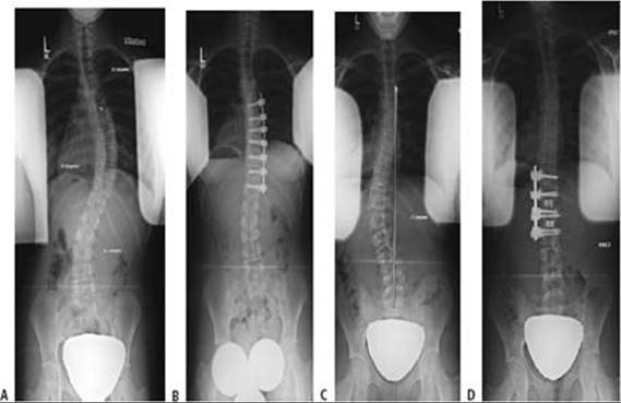
FIG 2 • A. Preoperative radiograph of a 13-year-old girl with a right thoracic curve measuring 52 degrees from T6 to T12. The disc at T11–12 is open into the right thoracic curve while the disc at T12-L1 is parallel. B.Thoracoscopic anterior spinal fusion and instrumentation from T6 to T12 demonstrating excellent correction of the main thoracic curve with excellent response of the proximal thoracic and lumbar curves. C. A left thoracolumbar curve measured between T11 and L2 with a trunk shift to the left. D. Two-year postoperative radiographs following an open anterior fusion and instrumentation from T11 to L2 with dual rod-dual screw system and anterior cages placed at the T12-L1 and L1-L2 levels with excellent coronal plane correction.
Positioning
Positioning for anterior surgery for either the thoracic or thoracolumbar curves is fairly similar.
Patients are placed in the lateral decubitus position with the convex side of the curve up.
An axillary roll is used for safe upper extremity neurologic function (FIG 3).
An inflatable bean bag is used to position the patient, and body positioners can be added for further patient stabilization.
For thoracolumbar–lumbar curves, a table that can be flexed allows for greater access to the abdomen and spine. It should be centered over the apex of the curve.
For thoracic scoliosis surgery, the patient can be placed on a flat radiolucent table.
Approach
The anterior approach is used for thoracic scoliosis.

FIG 3 • Positioning for access for a thoracoscopic anterior spinal fusion and instrumentation in the left lateral decubitus position. The arms are positioned at 90 degrees, axillary rolls are placed on the left axilla, and the patient is secured with a bean bag.
TECHNIQUES
OPEN THORACIC ANTERIOR INSTRUMENTATION AND ARTHRODESIS
 A curved incision is made over the proximal rib corresponding to the proximal fusion level (ie, commonly T5 with the fifth rib). The incision is carried through the thoracic and abdominal musculature to the periosteum of the rib.
Subperiosteal dissection of the rib is performed circumferentially, and the rib is cut posteriorly and anteriorly.
The parietal pleura is incised in a longitudinal fashion over the vertebral bodies across the intended levels of instrumentation and fusion.
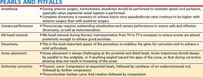
The segmental vessels can be temporarily ligated and spinal cord monitoring should be observed during temporary ligation.
Permanent ligation can be performed after 20 minutes of normal spinal cord monitoring.
Discectomy is performed (see below in the section on the thoracoscopic technique).
Instrumentation is placed (see below).
For the remaining procedures, see details under the thoracoscopic approach.
THORACOSCOPIC ANTERIOR INSTRUMENTATION AND ARTHRODESIS
Positioning, Preparation, and Draping
After true lateral positioning is confirmed, fluoroscopy is used to mark the skin for the proximal-end vertebra and distal-end vertebra on the AP view. The skin markings are made to identify the angle of the proximal-end vertebra on the AP view (TECH FIG 1).
The anterior and posterior edges of the vertebral bodies are then marked using the lateral fluoroscopy view.
The chest and flank are prepared and draped in the normal sterile fashion.
Thoracoscopic Portal and Guidewire Placement
An anterior portal is placed, bisecting the distance between the proximal and the distal intended instrumented vertebra, in the anterior axillary line. This portal is used for placement of the camera (TECH FIG 2A).
A guidewire is then placed directly over the vertebral bodies over the intended second-most-proximal portal and is visualized with the thoracoscope placed in the anterior portal (TECH FIG 2B).
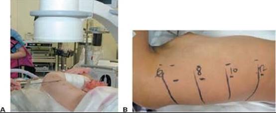
TECH FIG 1 • Fluoroscopic imaging of the spine prior to surgery. A. The lateral radiograph is used to identify the anterior and posterior edges of the vertebral body. B. The AP radiograph is used to mark the skin over the intended fusion levels to direct portal placement. This example demonstrates a T6–T12 fusion.

TECH FIG 2 • A. The anterior portal is placed in the anterior axillary line with the camera inserted in the portal. The patient is in the left lateral decubitus position: proximal to the right and distal to the left. B. A guidewire is placed before placing the posterior lateral portals. The guidewire is directed just anterior to the rib heads and marks a good position for the posterolateral portal.
After good placement of the guidewire (directly over the rib head), the portal is placed with a transverse incision centered over the rib. This portal can be used for visualization with a thoracoscope to place the remaining portals.
The most proximal posterolateral portal is placed after the intended second posterolateral portal to ensure exact location of the proximal portal. The proximal portal position is most important, since the most proximal two screws are often placed in small vertebral bodies and have significant coronal angulation, and retraction of the scapula makes this portal difficult.
The remaining portals are placed in the posterolateral line.
The portals will house the camera, a fan retractor to retract the lung, a suction device, a working portal, and then a free portal.
Discectomy Technique
The pleura is incised in the midvertebral line in a longitudinal fashion, keeping the segmental vessels intact (TECH FIG 3A).
The segmental vessels are then ligated two or three at a time (normotensive anesthesia is used for anterior surgery).
The parietal pleura is retracted anteriorly, all the way to the opposite side, and access to the anterior longitudinal ligament and the contralateral annulus is allowed (TECH FIG 3B).
Posterior retraction allows for identification of the rib heads (TECH FIG 3C).
The disc is incised from the convex rib head to the opposite annulus (TECH FIG 3D).
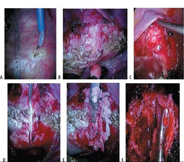

TECH FIG 3 • A. Electrocautery is used to incise the parietal pleura longitudinally, starting over the disc to avoid the segmental vessels. The segmental vessels are left intact on the first pass. B,C. After ligation of the segmental vessels, the pleura is bluntly retracted. B. Anterior dissection circumferentially to the opposite side of the pleura. C. Posterior retraction of the parietal pleura beyond the rib head. D.A scalpel blade is used to incise the annulus from rib head posteriorly all the way to the opposite annulus. Shown here is the incision up against the rib head after incising the annulus and the anterior longitudinal ligament. E. Disc shavers are used to break up the disc material. F. An angled curette is used to take down the endplate and tease the periosteum around the corner to get full access to the bone. G.The most anterior aspect of the rib head is being removed. Electrocautery is used to loosen the soft tissues attaching the rib head to the vertebral body. Part of the rib head has been removed in this photo.
The periosteum for the proximal and distal vertebra is incised to allow for subperiosteal dissection when the discectomy is performed.
Disc shavers are used to break up the disc material, using shavers of increasing width (TECH FIG 3E).
A rongeur is used to remove the annulus and nucleus pulposus.
An angled curette is used to take down the endplate circumferentially (TECH FIG 3F).
The rib head is removed at the T4–T7 levels. Since it is positioned relatively anterior on the vertebral bodies, it allows for good discectomy and good placement of the screws at these levels (TECH FIG 3G).
After discectomy, Gelfoam or Surgicel is placed in the disc space to prevent endplate bleeding.
Implant Placement and Grafting
Screw placement is performed beginning at the apex of the curve.
The proper screw position starts just anterior to the rib head and is angled in line with the midaxial plane of the vertebral body (angled anteriorly at the apex especially, with less angulation at the proximal distal levels) (TECH FIG 4A).
Screw position should be parallel to the endplate, and the proximal and distal levels should be angled toward the apex of the curve so that during correction, any screw plow will not loosen screws. Visualization of adjacent screws should confirm good alignment (TECH FIG 4B).
After screw placement, the screw height should be visualized to ensure that rod seating will occur without difficulty (TECH FIG 4C).
Autologous bone is packed into the disc space after removal of Gelfoam or Surgicel.
Rod placement is performed; rods can be seated either proximally or distally. Depending on rod flexibility and size, a straight rod is placed on the end and the set screws are engaged to secure the rod (TECH FIG 4D).


TECH FIG 4 • A. The screw-awl device is placed while visualizing a previously placed screw. The starting point is just anterior to the rib head in this photo. B. Final placement of a distal screw while visualizing the more proximal screws. The diaphragm is seen in the background. C. After screw placement, the height of the screws should be consistent to allow easy seating of the rod. D. The rod is inserted into the most distal screws. E.Compression across the most distal segment is first performed using the cable compressor. F. After distal compression, the rod is cantilevered to the remaining screw heads. G.AP intraoperative fluoroscopic image confirms good correction of the spine with maintenance of screw position. H. Lateral fluoroscopic image demonstrates good position of the screws with restoration of thoracic kyphosis. Rotational correction is also seen with rib margins symmetric. I. Closure of the parietal pleura over the instrumentation. J. Placement of chest tube under direct visualization while the lung is still deflated.
Compression across the initial levels is then performed to improve the coronaland sagittal-plane deformity (TECH FIG 4E).
The rod is then cantilevered down to the remaining screws, and compression is sequentially performed over those levels. Often the rod cannot be cantilevered down to all of the screws, so sequential cantilever and compression are performed (TECH FIG 4F).
Radiographs are obtained at this point and the desired correction is compared with the radiographs. Further compression is performed as needed. Care should be taken to ensure that screw plow or loosening is not occurring radiographically or visually (TECH FIG 4G,H).
Set screws are completely torqued down.
The pleura is closed over the instrumentation to ensure correct bone graft positioning, decreased chest tube drainage, and improved long-term pulmonary function (TECH FIG 4I).
The lung is inflated under direct visualization.
A chest tube is placed through the distal portal incision and tunneled to the proximal portal (TECH FIG 4J).
The incisions are closed in the normal fashion.
OPEN INSTRUMENTATION AND ARTHRODESIS OF THE THORACOLUMBAR–LUMBAR SPINE
Preparation and Exposure
The patient is placed in the lateral decubitus position with the convex side of the spine up.
An axillary roll is placed.
The bed can be flexed to allow for easier access to the flank (TECH FIG 5A).
A curved linear incision is made in line with the rib just proximal to the planned upper instrumented vertebra (TECH FIG 5B).
The incision is carried down through the subcutaneous layer through the various muscle layers down over the rib. The incision can be carried out distally lateral to the umbilicus.
Subperiosteal dissection is carried out around the rib. The rib is transected posteriorly near its insertion to the spine (TECH FIG 5C).
The costochondral junction is then incised. A marking suture is placed at the costochondral junction for later reapproximation (TECH FIG 5D).
Usually at the costochondral level at the 10th rib, access into the retroperitoneal space is quite easy, with retroperitoneal fat evident. The peritoneal contents are then bluntly dissected off the abdominal wall and the undersurface of the diaphragm (TECH FIG 5E).
The diaphragm is then incised just proximal to its insertion, and marking sutures are placed to ensure proper reapproximation (TECH FIG 5F).
A pleural incision is made longitudinally in line with the spine, leaving the segmental vessels intact (TECH FIG 5G).
Segmental vessel ligation is then carried out, maintaining good blood pressure to ensure good spinal cord perfusion (TECH FIG 5H).

TECH FIG 5 • A. Positioning for thoracoabdominal approach to the spine. The table is flexed to allow full access to the thoracoabdominal region. B. Skin incision is marked. This example is centered over the 10th rib for a T11–L3 fusion. C. The incision is made over the rib and subperiosteal dissection is carried out circumferentially around the rib after sequential dissection through the musculature. D. The posterior aspect of the periosteum is then incised and the chest is entered. E. After incision of the costochondral junction, the retroperitoneal fat is visualized and the retroperitoneal cavity is entered. F. The diaphragm is incised a fingerbreadth proximal to its insertion. G. The parietal pleura is incised proximally. H. Ligation of segmental vessels after suture tying.

TECH FIG 6 • A. Incision of the annulus with a scalpel blade. B. Endplate dissection off the bone using a Cobb elevator. C. Lexcel rongeur removal of the disc material.
Discectomy
Discectomies are performed with incision of the annulus fibrosis (TECH FIG 6A).
Endplate dissection is carried out, using a Cobb elevator to remove the entire endplate disc material back to the posterior aspect of the annulus and to the posterior longitudinal ligament if necessary (for severe curves; TECH FIG 6B).
The disc material is removed completely using rongeurs and curettes (TECH FIG 6C).
The disc space is packed with Surgicel.
Implant Placement, Correction, and Fusion
The instrumentation is then placed using single large screws with a quarter-inch single-rod implant system, or a dual rod with a 5.5-mm rod (shown here).
Screws are initially placed at the apex in the middle to posterior third of the vertebral body in the midaxial plane (TECH FIG 7A).
When using a dual-rod system, the posterior screws are initially placed angled in the midaxial plane, while the anterior screws are directed slightly posteriorly. A staple is often used when both the singleand dual-rod screws are used (TECH FIG 7B).
Once screws are placed, the bone graft material is placed as far back toward the posterior longitudinal ligament as possible, or the posterior rim of the annulus fibrosis.
The operating table should now be leveled to allow for correction of the spine.
The posterior rod is initially placed with the dual-rod system, and a 90-degree rod rotation removal can be performed (TECH FIG 7C).
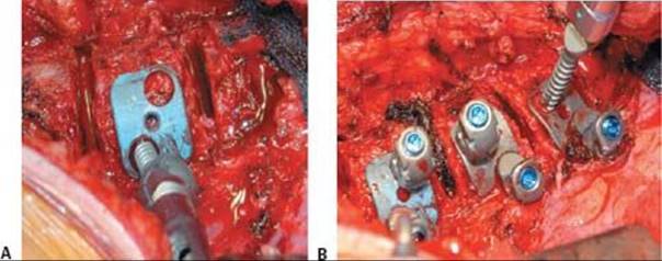

TECH FIG 7 • A. Placement of the posterior screw directed slightly anteriorly with direct visualization of the endplates after complete disc removal. B. Anterior screw placement after placement of the posterior screws. The anterior screws are directed slightly posteriorly. C. Insertion of the posterior rod with lumbar lordosis built into the rod. D. After 90 degrees of rod rotation, scoliosis correction is achieved while restoring lumbar lordosis, as shown here. E. After rod rotation, the anterior structural support is placed anteriorly and toward the concavity of the deformity. F. The anterior rod is seated into the anterior screws.
 Alternatively, directed force on the anterior screws to correct the coronal and axial plane is achieved, and then the posterior rod is inserted (TECH FIG 7D).
After rod rotation with a dual-rod system or single-rod system, or correction with pressure on the anterior screws and fixation with the posterior rod, the anterior structural support is placed. This is most commonly at levels distal to T12 or alternatively at all instrumented levels (TECH FIG 7E).
Compression can then be performed to further correct coronal-plane deformity.
The anterior structural support should be placed anteriorly and onto the concavity to ensure maintenance of the lordosis and improvement of coronal-plane correction.
The second anterior rod should be then placed with a dual-rod system and all set screws completely tightened (TECH FIG 7F).
The remaining bone graft material is then placed in the remaining disc space.
Closure
The pleura is closed as far distally as possible (TECH FIG 8A).
The diaphragm is reapproximated with interrupted Neurolon sutures (TECH FIG 8B).
The costochondral junction is reapproximated, and the periosteum of the rib is reapproximated (TECH FIG 8C).
A chest tube of fairly large diameter is then placed.
The abdominal wall is reapproximated in layers (TECHFIG 8D).
The remaining muscle layers are closed, as well as the skin and subcutaneous layers (TECH FIG 8E).
The postoperative radiographs are shown in TECH NIQUES FIGURE 8F AND 8G.


TECH FIG 8 • A. The parietal pleura is closed beginning proximal to the implants. B. Interrupted Neurolon sutures are used to close the diaphragm in an anatomic fashion. C. The ribs are reapproximated after placing no. 1 sutures under the proximal and distal ribs. D. Sequential closure of the muscle and soft tissue layers. E. Skin closure. F,G. The patient in Figure 1, 1 year postoperatively.
POSTOPERATIVE CARE
The chest tube should be placed to wall suction and can usually be removed between 48 and 72 hours, when the drainage decreases below 80 cc per shift and when it turns more strawcolored.
Serial hemoglobin and hematocrit levels should be obtained in the first 48 hours.
Advancing activities: Sitting in a chair the first postoperative day and walking on the second postoperative day ensures good postoperative pulmonary status and normal bowel function.
Postoperative bracing is used for 3 months for single-rod anterior thoracoscopic thoracic arthrodesis and instrumentation. No bracing is necessary with single quarter-inch rod instrumentation or dual-rod instrumentation when anterior structural support is used.
Normal activities are resumed when arthrodesis is visualized (best seen on the lateral radiograph).
OUTCOMES
Thoracoscopic anterior instrumentation and fusion achieves a good radiographic and functional outcome.
Thoracoscopic anterior instrumentation and fusion continues to have a fairly high pseudarthrosis rate of 5% to 6%.
Pulmonary function is somewhat decreased early in the postoperative period with anterior surgery, but then it can return to baseline at 1 to 2 years.
Thoracolumbar–lumbar anterior instrumentation and fusion results in excellent coronal-, axial-, and sagittal-plane realignment, especially when dual-rod and large single-rod instrumentation systems with anterior structural support are used.
COMPLICATIONS
Acute complications
 Infection is rare in anterior spine deformity surgery.
Atelectasis and mucous plugs can be seen, especially with single-lung ventilation with anterior instrumentation. Aggressive pulmonary toilet and resuming activities minimize this risk.
Late complications
Pseudarthrosis: The incidence is 4% to 10% for thoracic scoliosis (usually occurs at the apex of the curve) and 4% to 12% for thoracolumbar scoliosis (usually occurs at the distal fusion level).
Loss of correction with kyphosis is seen for thoracolumbar–lumbar curves treated anteriorly when anterior structural support is not used.
REFERENCES
· Bernstein RM, Hall JE. Solid rod short segment anterior fusion in thoracolumbar scoliosis. J Pediatr Orthop B 1998;7:124–131.
· Betz RR, Shufflebarger H. Anterior versus posterior instrumentation for the correction of thoracic idiopathic scoliosis. Spine 2001;26: 1095–1100.
· Bitan FD, Neuwirth MG, Kuflik PL, et al. The use of short and rigid anterior instrumentation in the treatment of idiopathic thoracolumbar scoliosis: a retrospective review of 24 cases. Spine 2002;27:1553–1557.
· Bullmann V, Halm HF, Niemeyer T, et al. Dual-rod correction and instrumentation of idiopathic scoliosis with the Halm-Zielke instrumentation. Spine 2003;28:1306–1313.
· Kaneda K, Shono Y, Satoh S, et al. New anterior instrumentation for the management of thoracolumbar and lumbar scoliosis: application of the Kaneda two-rod system. Spine 1996;21:1250–1262.
· Lenke LG, Newton PO, Marks MC, et al. Prospective pulmonary function comparison of open versus endoscopic anterior fusion combined with posterior fusion in adolescent idiopathic scoliosis. Spine 2004;29:2055–2060.
· Lonner BS, Kondrachov D, Siddiqi F, et al. Thoracoscopic spinal fusion compared with posterior spinal fusion for the treatment of thoracic adolescent idiopathic scoliosis. J Bone Joint Surg Am 2006;88A:1022–1034.
· Lowe TG, Alongi PR, Smith DAB, et al. Anterior single rod instrumentation for thoracolumbar adolescent idiopathic scoliosis with and without the use of structural interbody support. Spine 2003;28:2232–2242.
· Newton PO, Parent S, Marks M, et al. Prospective evaluation of 50 consecutive scoliosis patients surgically treated with thoracoscopic anterior instrumentation. Spine 2005;30:S100–109.
· Ouellet JA, Johnston CE II. Effect of grafting technique on the maintenance of coronal and sagittal correction in anterior treatment of scoliosis. Spine 2002;27:2129–2136.
· Picetti GD III, Pang D, Bueff HU. Thoracoscopic techniques for the treatment of scoliosis: early results in procedure development. Neurosurgery 2002;51:978–984.
· Sanders AE, Baumann R, Brown H, et al. Selective anterior fusion of thoracolumbar/lumbar curves in adolescents: when can the associated thoracic curve be left unfused? Spine 2003;28:706–714.
· Saraph VJ, Krismer M, Wimmer C. Operative treatment of scoliosis with the Kaneda anterior spine system. Spine 2005;30:1616–1620.
· Satake K, Lenke LG, Kim YJ, et al. Analysis of the lowest instrumented vertebra following anterior spinal fusion of thoracolumbar/lumbar adolescent idiopathic scoliosis: can we predict postoperative disc wedging? Spine 2005;30:418–426.
· Sucato D, Kassab F, Dempsey M. Thoracoscopic anterior spinal instrumentation and fusion for idiopathic scoliosis: a CT analysis of screw placement and completeness of discectomy. Scoliosis Research Society, Cleveland, Ohio, 2001.
· Sweet FA, Lenke LG, Bridwell KH, et al. Prospective radiographic and clinical outcomes and complications of single solid rod instrumented anterior spinal fusion in adolescent idiopathic scoliosis. Spine 2001;26:1956–1965.
· Wong H-K, Hee H-T, Yu Z, et al. Results of thoracoscopic instrumented fusion versus conventional posterior instrumented fusion in adolescent idiopathic scoliosis undergoing selective thoracic fusion. Spine 2004;29:2031–2039.