
Joseph F. Slade III† and Greg Merrell
DEFINITION
 Scaphoid nonunion describes a wide spectrum of conditions.
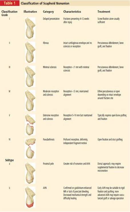
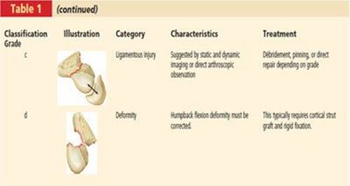
The classification system shown in Table 1 describes them in the context of treatment options.
ANATOMY
The scaphoid is almost entirely covered with cartilage and provides the mechanical link between proximal and distal carpal rows.
Blood supply is from volar and dorsal, entering distally. The volar artery supplies only the distal tubercle region. The proximal pole is primarily dependent on intraosseous blood supply, similar to the head of the proximal femur.
PATHOGENESIS
Mechanical instability and decreased perfusion are the most common causes of scaphoid nonunion.
These factors work to exacerbate each other. Micromotion disrupts vascular perforators (often the only blood supply), leading to bone resorption and further decrease in mechanical stability.
Proximal pole fractures are particularly at risk for nonunion for both mechanical (long distal lever arm and a small proximal contact area) and vascular reasons.
Infection is rarely a cause of scaphoid nonunion but should not be forgotten in the workup and treatment.
NATURAL HISTORY
Although progression is variable, patients often develop a dorsal intercalated segment instability (DISI) deformity (as described for scapholunate ligament injuries) and advance through stages of degeneration (scaphoid nonunion advanced collapse [SNAC] wrist arthritis) over decades.
 SNAC wrist stage I: affects only radial styloid; stage II: arthritis at radioscaphoid joint; stage III: involvement of the scaphocapitate and capitolunate joints; stage IV: pancarpal arthritis with preservation of the radiolunate joint
PATIENT HISTORY AND PHYSICAL FINDINGS
In established nonunions, patients present with wrist pain and in many cases are unaware of their original injury many years before.
Findings on examination typically include radial-sided wrist tenderness on palpation and decreased range of motion, particularly extension (secondary to the DISI deformity of the carpus).
Other than information regarding previous operative and nonoperative treatments, the additional information for evaluation and treatment decisions comes more from imaging.
IMAGING AND OTHER DIAGNOSTIC STUDIES
CT scan with 1-mm slices in the plane of the scaphoid can help delineate bony anatomy in established nonunions and can determine if there is any evidence of healing in early nonunions.
MR with intravenous contrast will help determine proximal pole vascularity.
The time and equipment required for vascularized bone grafting are more substantial than those needed for simple open reduction and internal fixation (ORIF) of the scaphoid with nonvascularized bone graft.
DIFFERENTIAL DIAGNOSIS
Bone cyst
Infection
Acute fracture
Pressier disease (scaphoid avascular necrosis [AVN])
NONOPERATIVE MANAGEMENT
If a nonunion has not previously been given a trial of conservative care and if there is no significant resorption, casting and a bone stimulator could be attempted prior to surgical fixation.
SURGICAL MANAGEMENT
Surgical treatment must solve three obstacles:
Re-establishment of local perfusion
Replacement of necrotic tissue with an osteoconductive and osteoinductive matrix
Stable fixation
Not all proximal pole nonunions with AVN require a vascularized graft.
If the distal scaphoid is well perfused and good fixation can be achieved, healing can proceed via creeping substitution.
Guidewire placement and reaming for screw fixation helps re-establish vascular channels.
Palmar flexion of the distal fragment and DISI position of the carpus must be corrected at the time of surgery.
The surgical technique described in this chapter is appropriate to repair grade I to III scaphoid nonunions.
If a grade IV nonunion lacks significant flexion deformity and has an intact fibrous shell to contain bone graft, one may consider treatment of these fractures using the minimally invasive method reviewed in this chapter.
Grade V and VI nonunions are characterized by substantial bone loss, synovial nonunion, and significant flexion deformity. They are therefore not suitable for percutaneous treatment.
Preoperative Planning
Advanced degenerative changes secondary to scaphoid nonunion are a relative contraindication to repair of a nonunion.
Advanced imaging, as discussed earlier, is crucial for appropriate preoperative planning.
Positioning
The patient is placed supine.
Traction for arthroscopy can be performed with either a traction tower or a simple horizontal pulley traction system.
Approach
A dorsal approach is used for proximal pole fractures to provide the most secure fixation (as a basic principle, think of securing the island to the mainland).
Waist fractures can be treated either dorsally or volarly.
The dorsal approach is preferred.
Nonunion of a distal pole scaphoid fracture, although rare, is best approached volarly.
TECHNIQUES
PLACEMENT OF THE TARGETING GUIDEWIRES
 A fluoroscopic survey is undertaken to evaluate the fracture, scaphoid alignment, and fragment mobility.
 Other occult carpal fractures are sought.
The wrist is ulnarly deviated to extend the distal fragment. A smooth 0.062-inch dorsal-to-volar targeting Kirschnerwire is placed in the distal fragment in the center position.
A smooth 0.062-inch lateral targeting wire is placed in the center of the distal fragment from radial to ulnar.
These Kirschner wires form a “crosshair” target to guide placement of the central axis guidewire (TECH FIG 1).
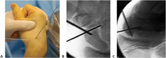
TECH FIG 1 • Crosshair targeting guide. A. External view. B. AP view. C. Central axis view.
Placement of the first central axis wire in the distal fragment is undertaken.
Place a 19-gauge needle into the fracture site and confirm position fluoroscopically.
Use the position of the needle to introduce a double-cut 0.045-inch Kirschner wire into the fracture site and down the medullary canal of the distal fragment, using the distal crossed targeting Kirschner wires as guides.
PLACEMENT OF THE DISTAL CENTRAL AXIS DEROTATION WIRE
Exit at the base of the thumb in an area devoid of neurovascular structures and withdraw it until the proximal tip is at the fracture site.
This first Kirschner wire will be used only to maintain a reduction and serve as a derotation wire, so perfect central axis placement is not necessary.
FRACTURE REDUCTION
From dorsal to volar drive a 0.062-inch Kirschner wire into the proximal fragment to serve as the proximal joystick.
Flex the distal dorsal-to-volar targeting Kirschner wire toward the proximal fragment joystick wire to correct the flexion deformity of the distal fragment (TECH FIG 2A,B).
Sometimes a percutaneous snap may need to be in-l troduced for additional leverage or to correct translational deformities.
Confirm fragment position fluoroscopically while holding the reduction.
Drive the distal fragment wire that is at the base of the thumb retrograde into the proximal fragment to secure the reduction (TECH FIG 2C).
Again, perfect placement in the proximal pole is not necessary, as this wire is used only temporarily.
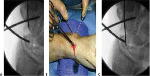
TECH FIG 2 • A. Fracture during reduction showing Kirschner wire positioned distally to capture reduction. B. Fracture reduction with joysticks. C. Radiograph of reduced fracture secured with a Kirschner wire.
PLACEMENT OF THE PROXIMAL CENTRAL AXIS GUIDEWIRE
With the wrist partially flexed and under fluoroscopy, impale a 19-gauge needle into the proximal ulnar corner of the proximal pole (TECH FIG 3A,B).
Drive a 0.045-inch Kirschner wire toward the thumb base, correcting its direction based on the external crossed-wire targeting guide.
A successfully placed central axis scaphoid wire will hit the crossing wires in the distal scaphoid.
The guidewire is driven volarly past this intersection, through the trapezium, and exits at the thumb base in a zone devoid of neurovascular structures.

TECH FIG 3 • A. Radiograph of a needle used to identify starting position for central axis wire. B. External view of starting position for central axis wire. C. Reduced fracture with antirotation wire.
The guidewire is withdrawn until the trailing edge crosses the radiocarpal joint and the wrist can be safely extended without bending the wire.
There are now two intramedullary Kirschner wires down the length of the scaphoid, one used to capture the initial reduction and the other placed down the long axis to be used as a guide for eventual screw insertion (TECH FIG 3C).
The use of two Kirschner wires limits bending forces and acts as an antirotation construct during scaphoid reaming and screw placement.
ARTHROSCOPIC EVALUATION AND REAMING
The arm is exsanguinated and the extremity is placed in a traction tower with 12 pounds distributed between four finger traps.
Fluoroscopy can be used with 19-gauge needles to identify the radiocarpal and midcarpal portals.
This maneuver limits iatrogenic injury to the joint, which can result from multiple attempts to introduce a blunt trocar blindly.
A small hemostat is used to separate the soft tissue and enter the wrist joint. A blunt trocar is placed at the radial midcarpal portal and a small joint angled arthroscope is introduced.
Additional 19-gauge needles are inserted to establish outflow.
A probe is introduced at the ulnar midcarpal portal, and the competency of the carpal ligaments is evaluated by directly stressing their attachments to detect partial and complete tears.
Any scapholunate interosseous ligament (SLIL) injury detected is graded using the Geissler grading system.2
Grade I and II ligament injuries are treated with débridement and shrinkage alone.
Grade III injuries are treated with débridement and, after fracture repair, carpal pinning for 6 weeks.
Grade IV instability requires open repair of the dorsal SLIL ligament with or without capsulodesis.
Tears of the triangular fibrocartilage complex are classified using the Palmer classification and are treated based on established guidelines.
Fracture reduction is thoroughly evaluated arthroscopically.
It is important to determine the presence of a fibrous capsule around the nonunion site. If there is no fibrous capsule, percutaneous bone graft is contraindicated as it will dissipate into the surrounding synovial fluid.
If vascularity of the proximal fragment is in question, flex the wrist in the traction tower.
Drive the central axis guidewire retrograde through the proximal fragment, ream over the wire to the level of the nonunion site.
Withdraw the central axis wire to the fracture site (while keeping the derotation Kirschner wire in place to maintain reduction) and introduce the scope into the proximal fragment through the previously reamed tract.
Stop the inflow and let down the tourniquet. Inspect the cancellous bone of the proximal pole with the scope for the appearance of punctate bleeding (TECH FIG 4).
Keep the wrist in a flexed position and retrograde the central axis wire so it is equally exposed dorsally and volarly.
Hand ream, under fluoroscopy, to within 2 mm of the distal cortex. Then withdraw the central axis wire volarly back to the level of the fracture site.

TECH FIG 4 • Inspect the cancellous bone of the proximal pole with the scope for the appearance of punctate bleeding. A. Devascularized proximal pole with no punctate bleeding. B. Vascularized proximal pole.
DÉBRIDEMENT OF THE NONUNION SITE AND BONE GRAFTING
A grade I scaphoid nonunion (delayed presentation) typically does not require débridement or bone grafting.
For grade II or III nonunions, insert a small curved curette through the path that was just reamed and débride the nonunion site (TECH FIG 5A).
Avoid disrupting the peripheral fibrous shell so there is a contained cavity within which to pack bone graft.
Using an 8-gauge bone biopsy needle, harvest cores of cancellous bone from either the distal radius or iliac crest. Introduce the bone biopsy cannula into the reamed proximal pole tract.
Pack plugs of bone graft through the cannula into the nonunion site until the radiolucent image of the nonunion site becomes radiopaque (TECH FIG 5B).

TECH FIG 5 • A. Percutaneous curette of nonunion. B. Nonunion site filled with percutaneous bone graft.
FIXATION
The wrist is flexed and the central axis scaphoid guidewire at the base of the thumb is driven dorsally.
The wire is adjusted until the trailing end is in the subchondral bone of the distal scaphoid pole.
A second wire of equal length is placed percutaneously against the proximal scaphoid pole, next to and parallel with the guidewire.
The difference in length between the trailing end of each wire represents the scaphoid length. The screw length selected should be 4 mm less than the scaphoid length.
This permits 2 mm of clearance of the screw at each end of the scaphoid, thus ensuring complete implantation without screw prominence.
The most common reported complication of percutaneous screw stabilization for scaphoid fractures is implantation of a screw that is too long.1
Advance the central axis wire so it is exposed equally volar and dorsal.
Re-ream the entire path of the screw to within 2 mm of the opposite cortex. This creates a path through the bone graft for the screw and prevents exploding the graft through the cortical shell with a blunt screw.
The scaphoid should never be reamed to the opposite bone cortex (overdrilling). This reduces fracture compression and increases the risk of motion at the fracture site.
Place the headless cannulated screw. If the screw is advanced to the distal cortex, attempts to advance the screw further will force the fracture fragments to gap and separate.
A standard-size Acutrak screw will best resist flexion moments.4
In unstable nonunions, as the screw is advanced it is advisable to use the joysticks to maintain a counterforce compression at the fracture site.
If screw fixation provides only modest stability, additional fixation is advantageous.
In proximal pole nonunions the bending forces of the long lever arm of the distal scaphoid can be neutralized with a Kirschner wire or screw from the distal scaphoid into the capitate (TECH FIG 6A).
Micromotion can be decreased with a Kirschner wire down the second or third web space locking the capitolunate articulation.
With the wrist partially flexed the radiolunate joint can be secured with a Kirschner wire, preventing the tendency of DISI position (TECH FIG 6B).
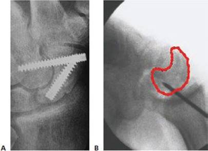
TECH FIG 6 • A. Decreasing lever arm with scaphocapitate screw. B. Helping dorsal intercalated segment instability (DISI) reduction by pinning lunate with wrist flexed.

POSTOPERATIVE CARE
A short-arm volar splint and bulky dressing are applied in the operating room and the patient returns in 1 week for suture removal.
If fixation is secure (as in a waist nonunion), then additional immobilization is not necessary.
Proximal pole nonunions, especially those with AVN, or other unstable patterns are protected with a short-arm cast until bridging bone is visible on CT scan.
Early finger motion and gentle hand strengthening are encouraged to reduce swelling and promote axial loading, encouraging fracture healing.
Serial CT scans can be performed every 6 weeks to assess healing.
Plain radiographs are not reliable for assessing healing.
Clinical symptoms are also not a reliable indicator of healing. Rigid fixation alone may provide a painless wrist after surgery before actual bridging bone has occurred.
Contact sports and heavy labor are restricted until healing is confirmed on CT.
OUTCOMES
The only published series of nonunions treated percutaneously is a select series of 15 patients with minimal resorption treated with screw fixation alone. All healed, as demonstrated by bridging bone on CT scans.3
Many grade I to IV nonunions have been successfully treated with this technique (data not yet published).
As more case series are reported, we will be better able to define the functional outcomes, indications, contraindications, and rate of union of percutaneous treatment of these injuries.
COMPLICATIONS
Complications are often related to screw placement.
Screws placed outside the central axis have less stable fixation and therefore an increased risk of nonunion.
A screw that is too long risks wear of the radioscaphoid joint.
Infection and scar tenderness are reported complications but are uncommon.
REFERENCES
1. Bond CD, Shin AY, McBride MT, et al. Percutaneous screw fixation or cast immobilization for nondisplaced scaphoid fractures. J Bone Joint Surg Am 2001;83:483–488.
2. Geissler WB, Freeland AE, Savoie FH, et al. Intracarpal soft-tissue lesions associated with an intra-articular fracture of the distal end of the radius. J Bone Joint Surg Am 1996;78A:357–365.
3. Slade JF III, Geissler WB, Gutow AP, et al. Percutaneous internal fixation of selected scaphoid nonunions with an arthroscopically assisted dorsal approach. J Bone Joint Surg Am 2003;85A(Suppl 4):20–32.
4. Toby EB, Butler TE, McCormack TJ, et al. A comparison of fixation screws for the scaphoid during application of cyclic bending loads. J Bone Joint Surg Am 1997;79A:1190–1197.