
Craig S. Mauro, Anthony M. Buoncristiani, and Christopher D. Harner
DEFINITION
 The posterior cruciate ligament (PCL) serves as the primary restraint to posterior translation of the tibia relative to the femur.
PCL injuries are uncommon, may be partial or complete, and rarely occur in isolation.
Our understanding of the PCL with respect to its natural history, surgical indications and technique, and postoperative rehabilitation is improving rapidly.
ANATOMY
The PCL has a broad femoral origin in a semicircular pattern on the medial femoral condyle.
 It inserts on the posterior aspect of the tibia, in a depression between the medial and lateral tibial plateaus, 1.0 to 1.5 cm below the joint line.
Its width, on average, is 13 mm, which is variable along its course; the average length is 38 mm.
Anatomic studies have delineated separate characteristics of the anterolateral (AL) and posteromedial (PM) bundles within the PCL.
The AL bundle origin is more anterior on the intercondylar surface of the medial femoral condyle, and the insertion is more lateral on the tibia, relative to the PM bundle.
The larger AL bundle has increased tension in flexion, whereas the PM bundle becomes more taut in extension.
The meniscofemoral ligaments, which arise from the posterior horn of the lateral mensicus and insert on the posterolateral aspect of the medial femoral condyle, also contribute to the overall strength of the PCL.
PATHOGENESIS
Acutely, there usually is a history of a direct blow to the anterior lower leg. Common mechanisms include high-energy trauma and athletic injuries.
In motor vehicle trauma, the “dashboard injury” occurs when the proximal tibia strikes the dashboard, causing a posteriorly directed force to the proximal tibia.
Athletic injuries usually involve a direct blow to the anterior tibia or a fall onto a flexed knee with the foot in plantar flexion.
Hyperextension injuries, which often are combined with varus or valgus forces, often result in combined ligamentous injuries.
NATURAL HISTORY
There is little conclusive clinical information regarding the natural history of patients with PCL tears treated nonoperatively.
Most studies suggest that patients with isolated grade I–II PCL injuries usually have good subjective results, but few achieve good functional results.11,13,14
A high incidence of degeneration, primarily involving the medial femoral condyle and patellofemoral joint, has been noted in patients treated nonoperatively. This finding is especially prevalent in those patients with grade III injuries or combined ligamentous injuries.
Consequently, pain rather than instability may be the patient's primary symptom following a PCL injury treated nonoperatively.
PATIENT HISTORY AND PHYSICAL FINDINGS
The initial history should focus on the mechanism of injury, its severity, and associated injuries.
With acute injuries, the patient often does not report feeling a “pop” or “tear,” as often is described with ACL injuries.
The history also should focus on assessing the chronicity of the injury and the instability and pain experienced by the patient.
A complete knee examination, including inspection, palpation, range of motion (ROM) testing, neurovascular examination, and special tests, should be performed.
Posterior drawer test: the most accurate clinical test for PCL injury
Posterior sag (Godfrey) test: A positive result is an abnormal posterior sag of the tibia relative to the femur from the force of gravity. This result suggests PCL insufficiency if it is abnormal compared to the contralateral side.
Quadriceps active test: useful in patients with combined instability. A posteriorly subluxed tibia that reduces anteriorly is a positive result.
Reverse pivot shift test: A palpable reduction of the tibia occuring at 20 to 30 degrees indicates a positive result. The contralateral knee must be examined, because a positive test may be a normal finding in some patients.
Dial test: A positive test is indicated by asymmetry in external rotation. Asymmetry of more than 10 degrees at 30 degrees rotation indicates an isolated posterolateral corner (PLC) injury, while asymmetry at 30 and 90 degrees suggests a combined PCL and PLC injury.
Posterolateral external rotation test: Increased external rotation of the tibia is a positive result. Increased posterior translation and external rotation at 90 degrees indicate a PLC or PCL injury, while subluxation at 30 degrees is consistent with an isolated PLC injury.
It is important to assess the neurovascular status of the injured limb, especially if there is a history of a knee dislocation.
IMAGING AND OTHER DIAGNOSTIC STUDIES
Radiographs of the knee should be performed following an acute injury to assess for a fracture. An avulsion of the tibial insertion of the PCL may be identified on a lateral radiograph (FIG 1A).
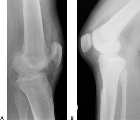
FIG 1 • A. Avulsion fracture of the tibial insertion of the posterior cruciate ligament (PCL). B. Posterior subluxation of the tibia in a case of chonic PCL deficiency.
In the chronic setting, radiographs may identify posterior tibial subluxation (FIG 1B) or medial and patellofemoral compartmental arthrosis.
Stress radiographs may be used to confirm and quantify dynamic posterior tibial subluxation.8
Long-cassette films should be obtained if coronal malalignment is suspected.
MRI is important to confirm a PCL injury, determine its location and completeness, and assess for concomitant injury, including meniscal and PLC pathology.
DIFFERENTIAL DIAGNOSIS
Combined ligament injury
PLC injury
ACL tear
Tibial plateau fracture
Articular cartilage injury
Medial or lateral collateral ligament tear
Meniscal tear
Patellar or quadriceps tendon rupture
Patellofemoral dislocation
NONOPERATIVE MANAGEMENT
Most experts advocate nonoperative management of isolated, partial PCL injuries (grades I and II).
In these cases, we recommend immobilization in full extension with protected weight bearing for 2 weeks. The goal is to protect the healing PCL/PLC.
ROM exercises are advanced as tolerated, and strengthening is focused on the quadriceps muscles.
Closed chain exercises (foot on the ground) are recommended.
Applying an axial load across the knee causes anterior translation of the tibia because of the sagittal slope.4 This important biomechanical principle allows early ROM exercises and protects PCL/PLC healing.
The patient usually can return to athletic activities after isolated grade I and II PCL injuries in 4 to 6 weeks. It is important to protect the knee from injury during this time to prevent progression to a grade III injury.
Functional bracing is of little benefit after return to sports activities.
Isolated grade III injuries are more controversial, and nonoperative management may be appropriate in certain patients.
We recommend immobilization in full extension for 2 weeks to prevent posterior tibial subluxation. Weight bearing is protected during these 2 weeks, then slowly advanced.
Quadriceps strengthening such as quadriceps sets and straight leg raises is encouraged; hamstring loading is prohibited until later in the rehabilitation course.
After 1 month, ROM, full weight-bearing, and progression to functional activities are instituted.
Return to sports usually is delayed for 2 to 4 months in patients with grade III injuries.
SURGICAL MANAGEMENT
Surgical indications include those patients with displaced bony avulsions, acute grade III injuries with concomitant ligamentous injuries, and chronic grade II–III injuries with symptoms of instability or pain.
With any PCL injury, it is imperative to assess the PLC to rule out injury, because surgery is indicated for combined injuries.
In higher-level athletes, surgical treatment may be considered for acute isolated grade III PCL injuries.
The timing of PCL reconstruction depends on the severity of the injury and the associated, concomitant ligamentous injuries.
Displaced bony avulsions and knees with multiligamentous injuries should be addressed within the first 3 weeks to provide the best opportunity for anatomic repair.5
A number of graft options are available for PCL reconstruction.
Autologous tissue options include bone–patellar tendon–bone, hamstring tendons, and quadriceps tendons.
Allograft options include tibialis anterior tendon, Achilles tendon, bone–patellar tendon–bone, and quadriceps tendon.
Advantages of allograft tissue include decreased surgical time and no harvest site morbidity. Disadvantages include the possibility of disease transmission. The operating surgeon should discuss these issues with the patient preoperatively.
Currently, allograft tibialis anterior tendon is our graft of choice for singleand double-bundle PCL reconstructions (FIG 2).
Preoperative Planning
In the office setting, the surgeon should have a variety of options available and explain that the final surgical plan will depend on the examination under anesthesia (EUA) and the diagnostic arthroscopy.

FIG 2 • Double-stranded tibialis anterior allograft sutured through an EndoLoop (Ethicon, Inc).
In the preoperative holding area, sciatic and femoral nerve block catheters may be placed by the anesthesiology staff.
No anesthetic is introduced, however, until neurologic assessment has been completed.
After anesthesia induction in the operating room, an EUA is performed on both the nonoperative and the operative knees.
A detailed examination is performed to determine the direction and degree of laxity.
Data from the contralateral knee may be particularly helpful with combined injuries.
Fluoroscopy may be used after the EUA to assess posterior tibial displacement.
Positioning
The patient is positioned supine on the operating room table.
We do not use a tourniquet.
Depending on the anticipated length of the planned procedure, a Foley catheter may be used.
A padded bump is taped to the operating room table to hold the knee flexed to 90 degrees. A side post is placed on the operative side just distal to the greater trochanter to support the proximal leg with the knee in flexion (FIG 3A). Padded cushions are placed under the nonoperative leg.
For the inlay technique, a gel pad bump is placed under the contralateral hip to facilitate later exposure to the posteromedial knee of the operative extremity in the figure 4 position.
After prepping and draping the operative site, a hole is cut in the stockinette for access to the dorsalis pedis pulse throughout the case (FIG 3B).
Approach
Several techniques have been described for PCL reconstruction. We have developed the following treatment algorithm:
For acute injuries, we employ the single-bundle technique.
If some component of the native PCL remains, we spare this tissue and use the augmentation technique.
 This technique can be time-consuming and difficult, but preservation of PCL tissue may provide enhanced posterior stability of the knee and may promote graft healing.
We most commonly perform the double-bundle technique in the chronic setting, when any remaining structures are significantly incompetent.
Some authors advocate the tibial inlay technique for all settings. We typically do not use this technique, but have included a description of an open double-bundle technique here as part of a comprehensive overview. All arthroscopic tibial inlay techniques also have recently been described.6,9
In cases of displaced tibial avulsion, we use the technique described in the Techniques box.

FIG 3 • A. Operative field setup, demonstrating the bump holding the knee flexed to 90 degrees and a side post supporting the proximal leg with the knee in flexion. B. Stockinette with hole cut out to palpate the dorsalis pedis pulse.
TECHNIQUES
SINGLE-BUNDLE TECHNIQUE
Diagnostic Arthroscopy
 A bump is placed between the post and the leg to stabilize the knee in a flexed position while the foot rests on the pre-positioned sandbag.
 The knee is flexed to 90 degrees, and the vertical arthroscopy portals are delineated.
The anterolateral portal is placed just lateral to the lateral border of the patellar tendon and adjacent to the inferior pole of the patella.
The anteromedial portal is positioned 1 cm medial to the medial border of the superior aspect of the patellar tendon.
Diagnostic arthroscopy is conducted to determine the extent of injury and evaluate for other cartilage or meniscal derangements.
The notch is examined for any remaining intact PCL fibers. If augmentation is to be performed, care should be taken to preserve these fibers (see Single-Bundle Augmentation Technique).
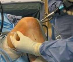
TECH FIG 1 • The posteromedial portal is established under direct visualization using a spinal needle.
Using an arthroscopic electrocautery device and shaver, overlying synovium and ruptured PCL fibers are débrided, and the superior interval between the ACL and PCL is defined.
An accessory posteromedial portal is created just proximal to the joint line and posterior to the MCL.
A 70-degree arthroscope is placed between the PCL remnants and the medial femoral condyle to assess the posterior horn of the medial meniscus and to localize the posteromedial portal with a spinal needle (TECH FIG 1).
A switching stick can be placed into the posteromedial portal to facilitate exchange of the arthroscope. The 30-degree arthroscope is used when viewing via the posteromedial portal.
A transseptal portal also may be created for better visualization of and access to the tibial PCL insertion.1,10
Preparation and Exposure of the Tibia
Correct preparation and exposure of the tibia is essential for drilling the tunnel safely in the appropriate position.

TECH FIG 2 • A. Posterior cruciate ligament (PCL) drill guide positioned to facilitate guide pin exit at the PCL insertion. B. Once the PCL drill guide is set, it is confirmed arthroscopically and fluoroscopically. C. The tibial guidewire is drilled under fluoroscopic guidance. D. The tibial guidewire position is confimed with fluoroscopy.
First the 70-degree arthroscope is placed into the anterolateral portal, and a commercially available PCL curette is introduced through the anteromedial portal.
A lateral fluoroscopic image can be obtained to confirm its position.
The 30-degree arthroscope is then introduced through the posteromedial portal. The soft tissue on the posterior aspect of the tibia is carefully elevated centrally and slightly laterally.
A shaver can be placed through the anterolateral portal to débride some of the surrounding synovium.
The 70-degree arthroscope is returned to the anterolateral portal and the shaver placed in the posteromedial portal to complete the exposure.
Creating the Tibial Tunnel
A commercially available PCL tibial drill guide set to 55 degrees is advanced through the anteromedial portal and placed just distal and lateral to the PCL insertion site, 1.5 cm distal to the articular edge of the posterior plateau along the sloped face of the posterior tibial fossa (TECH FIG 2A).
The position is checked fluoroscopically using a lateral view and arthroscopically via the posteromedial portal.
An incision and dissection through periosteum to bone is made on the anteromedial aspect of the tibia in line with the guide.
The PCL guide is set, and its position is confirmed with fluoroscopy and arthroscopy (TECH FIG 2B).
A guidewire is drilled to but not through the posterior cortex.
Fluoroscopy is used to confirm the path of the guidewire (TECH FIG 2C,D).
With the 30-degree arthroscope in the posteromedial portal, the PCL curette is introduced through the anteromedial portal and is used to protect the posterior knee structures as the guidewire is carefully advanced through the posterior cortex under arthroscopic visualization.
A parallel pin guide can be used to make small pin placement corrections if necessary.
A cannulated compaction reamer is used to drill the tibial tunnel.
The tibial cortex is cautiously perforated by hand reaming under arthroscopic visualization.
The tunnel is irrigated, and increasing serial dilators are used under arthroscopic visualization up to the graft size.
Creating the Femoral Tunnel
An angled awl, via the anterolateral portal, is used to create a starting hole at the 1:00 (right knee) or 11:00 (left knee) position.
The anteroposterior position depends on the size of the graft, but the hole should be positioned so the tunnel edge is located at the junction with the articular cartilage (TECH FIG 3).
A guidewire is impacted into the starting hole via the anterolateral portal.
An appropriately sized cannulated acorn reamer is carefully passed over the guidewire, taking into consideration the close proximity of the patellar articular surface.
The tunnel is drilled to a depth of approximately 30 mm, taking care to avoid penetrating the outer cortex of the medial femoral condyle.
Increasing serial dilators are passed to match the size of the graft.
A smaller EndoButton drill (Smith & Nephew, Andover, MA) is used to perforate the outer cortex of the medial femoral condyle, and a guidewire is inserted through the anterolateral portal into the femoral tunnel.
An incision is made parallel to Langer's lines over the anteromedial aspect of the distal medial femoral condyle, at the estimated exit of the guidewire from the bone.
The vastus medialis obliquus fascia and muscle is split in line with their fibers, and the muscle and periosteum are elevated off the anteromedial distal femur.
The drill hole is exposed and guidewire is removed.

TECH FIG 3 • The femoral tunnel is positioned so the tunnel edge is located at the junction with the articular cartilage.
Graft Passage
Passage of the graft may require enlarging the anterolateral portal.
The 30-degree arthroscope is placed in the posteromedial portal, and a long 18-gauge bent wire loop is passed with the loop bent upward from anterior and distal to posterior and proximal through the tibial tunnel.
A tonsil is introduced through the anterolateral portal and through the notch to retrieve the bent wire loop (TECH FIG 4).
Leading sutures from the free ends (tibial side) of the graft are placed through the wire loop.
The wire and sutures are pulled back through the tibial tunnel in an anterograde fashion.
A small scooped malleable retractor is introduced through the anterolateral portal and placed just posterior to the femoral tunnel to retract the fat pad and provide an unobstructed path for a Beath pin.
A Beath pin is then passed through the anterolateral portal and through the femoral tunnel.
The lead suture limbs from the EndoLoop (Ethicon, Inc.) side of the graft are threaded through the eye of the Beath pin.
The pin, with the suture limbs, is pulled proximally.
Traction on the suture limbs pulls the graft into the femoral tunnel to the marked line, while traction of the tibial suture limbs pulls the graft into the femoral tunnel.
The position of the graft is confirmed arthroscopically.
Graft Fixation
Graft fixation is achieved by placing the EndoLoop along the medial femur with a tonsil to estimate its most proximal extent.
A 3.2-mm drill bit is used to make a unicortical hole at the most proximal extent of the EndoLoop.
After the hole is measured and tapped, a 6.5-mm cancellous screw and washer are placed through the EndoLoop into the femur.
The screw is tightened as the graft is pulled tight distally.
The fixation is palpated to ensure the EndoLoop limbs are tight distal to the screw and washer.

TECH FIG 4 • A long 18-gauge bent wire loop, used to pass the sutures through the tibial tunnel in an anterograde fashion, is retrieved through the anterolateral portal.
An anterior tibial force is applied to reduce the tibia before and during final tibial fixation.
A cortical 4.5-mm screw and washer are placed from anteromedial to posterolateral within the proximal tibia.
The graft is fixed at 90 degrees flexion.
Before the screw advances to the second cortex, the suture limbs from the tibial side of the graft are tied with tension over the post. The screw is then tightened.
The arthroscope is inserted to confirm adequate position, tension, and fixation of the graft.
Wound Closure
The incisions are irrigated, and the fascia in the anterolateral femoral incision is closed with size 0 Vicryl suture.
The subcutaneous layer is approximated with interrupted, inverted 3-0 Vicryl suture, and the skin is closed with a running 4-0 absorbable suture.
The portals are closed with 3-0 nylon suture.
The dorsalis pedis and posterior tibialis pulses are assessed by palpation and a Doppler ultrasound examination if necessary.
The incisions are covered with adaptic gauze and sterile gauze, then wrapped in cast padding and bias wrap.
SINGLE-BUNDLE AUGMENTATION
When preparing the medial femoral condyle for tunnel drilling, care again is taken to preserve the intact PCL bundle.
The starting hole is placed at the 1:00 (right knee) or 11:00 (left knee) position.
The hole should be positioned in the anteroposterior plane so the tunnel edge is located at the junction with the articular cartilage.
This location depends on the size of the graft and the distance from the intact PM bundle.
The graft is passed around the intact bundle, which is the final augmentation consideration.
Fixation and closure are then performed.
For single-bundle augmentation, much of the technique is identical to the single-bundle technique already described.
Often, the AL bundle is ruptured and the PM bundle remains intact. Consequently, for the purposes of this chapter, AL bundle augmentation will be described.
The diagnostic arthroscopy is performed.
If the AL bundle is found to be intact, special care is taken to preserve this bundle while the overlying synovium and ruptured PCL fibers are débrided (TECH FIG 5A).
When preparing the posterior aspect of the tibia, preservation of the PCL origin is essential.
Tibial tunnel preparation is performed similarly to the single-bundle technique.
The exit point for the guide pin along the sloped face of the posterior tibial fossa is just distal and lateral to the intact PCL insertion site (TECH FIG 5B).

TECH FIG 5 • A. An intact AL bundle is preserved and the overlying synovium and ruptured PCL fibers are débrided. B. The exit point for the tibial tunnel along the sloped face of the posterior tibial fossa is just distal and lateral to the intact PCL insertion, as demonstrated by a long 18-gauge bent wire loop.
DOUBLE-BUNDLE RECONSTRUCTION
For double-bundle PCL reconstruction, the initial aspects of the technique are identical to those of single-bundle reconstruction, including portal placement, arthroscopy, and preparation for drilling.
Tibial Tunnel Creation
Throughout this process, care must be taken to avoid tunnel convergence and ensure an adequate bony bridge between the two tibial tunnels.
First, the guide pin for the AL tunnel is positioned using the same technique as with single-bundle reconstruction.
It exits the tibia just distal and lateral to the PCL insertion site, 1.5 cm distal to the articular edge of the posterior plateau.
The PCL guide is reintroduced into the joint.
The same steps and precautions are repeated for placement of the PM tibial guidewire.
The PM tibial guidewire enters the tibia on the anteromedial aspect of the tibia, slightly more proximal and medial than the AL guidewire.
Conversely, the PM guidewire can be introduced through the anterolateral tibia, crossing the AL guidewire on the coronal view, but remaining proximal to the AL guidewire throughout its course on the sagittal view. It exits the tibia in the footprint more medial and slightly proximal to the AL tibial guidewire (TECH FIG 6A).
It is important to ensure adequate separation between the two guide pins to accommodate both tunnels with a bony bridge separation.

TECH FIG 6 • A. Both the AL and PM guidewires are positioned in the proximal posterior tibia. The PM guidewire, and subsequently the tunnel, exits the tibia in the footprint more medial and slightly proximal to the AL tibial guidewire. B. Dilators demonstrate the position of the AL and PM tunnels in the proximal posterior tibia.
Once the guidewire positions are satisfactory, a cannulated compaction reamer is used to first drill the AL tibial tunnel.
The drill is advanced under fluoroscopic guidance.
The posterior tibial cortex is cautiously perforated by hand reaming under arthroscopic visualization.
The tunnel is irrigated, and increasing serial dilators are used under arthroscopic visualization.
The steps are repeated for drilling the PM tibial tunnel with a 7-mm cannulated compaction reamer (TECH FIG 6B).
Femoral Tunnel Creation
An angled awl is used to create the starting holes.
For the AL bundle, the starting hole is placed at the 1:00 (right knee) or 11:00 (left knee) position.
The hole should be positioned in the anteroposterior plane so the tunnel edge is located at the junction with the articular cartilage.
The guidewire is passed via the anterolateral portal and impacted into the starting hole.
The appropriately sized cannulated acorn reamer is passed over the guidewire.
The reamer should be passed carefully, given the close proximity of the patellar articular surface.
The tunnel is drilled to a depth of about 30 mm, with care taken to avoid penetration of the outer cortex of the medial femoral condyle.
Increasing serial dilators are passed to match the size of the graft.
A smaller EndoButton drill (Smith & Nephew, Andover, MA) is used to perforate the outer cortex of the medial femoral condyle.
This inside-out femoral tunnel preparation technique is then repeated for the PM tunnel.
The angled awl is used to create the starting hole at the 3:00 (right knee) or 9:00 (left knee) position.
The PM tunnel is placed parallel or slightly posterior to the AL tunnel.
The guide pin is then placed via the anterolateral portal and impacted into the starting hole.
A 7-mm acorn reamer is passed over the guidewire and drilled to a depth of approximately 30 mm (TECH FIG 7).
The medial femoral condylar cortex is perforated with the EndoButton drill.

TECH FIG 7 • The femoral tunnels, with the AL tunnel at the 11:00 position and the PM tunnel at the 9:00 position.
Graft Placement and Fixation
The AL graft is passed first, using the same technique as with single-bundle reconstruction.
This process is then repeated for the PM graft (TECH FIG 8).
It is helpful to keep tension on the AL graft suture ends when passing the PM graft to ensure that the AL graft does not get pulled into the joint.
Graft fixation is performed first on the femoral side.
The AL bundle is secured as previously described.
This process is repeated for the PM bundle, ensuring that adequate separation exists between the two screws and washers to prevent overlap.
An anterior tibial force is applied to reduce the tibia before and during final tibial fixation.
Two 4.5-mm cortical screws and washers are placed from anteromedial to posterolateral within the proximal tibia, just distal to the respective tunnels.
As with the single-bundle technique, before the screw advances to the second cortex, the suture limbs from the tibial side of the graft are tied with tension over the post, and then the screw is tightened.
The AL graft is secured first at 90 degrees flexion, and the PM bundle then is secured at 15 degrees of flexion.
The arthroscope is inserted to confirm adequate position, tension, and fixation of the grafts.

TECH FIG 8 • The double-bundle reconstruction with the grafts in place.
Tibial Inlay
For the double-bundle tibial inlay PCL reconstruction, the initial aspects of the technique are similar to those for single-bundle reconstruction, including portal placement, arthroscopy, and débridement.
A whole, nonirradiated, frozen patellar tendon allograft is prepared with two bundles attached to a common tibial bone block and distinct femoral bone blocks.
The tibial bone block is fashioned from the tibial side of the graft and should measure 20 mm long, 13 mm wide, and 12 mm thick.
 A single 4.5-mm gliding hole is placed in the center of the block for later fixation.
The tendon bundles stemming from the tibial bone block should measure 11 mm (AL bundle) and 9 mm (PM bundle).
The femoral bone plugs from the patellar side of the graft are shaped to 20 mm in length and 11 mm (AL bundle) and 9 mm (PM bundle) in diameter.
The femoral bone plugs are each drilled with two separate 2.0-mm holes, through which Fiberwire (Arthrex, Naples, FL) passing sutures are placed (TECH FIG 9A).
The leg is brought into a figure 4 position, with the knee flexed to 90 degrees and the bump repositioned under the lateral ankle.
A 6-cm incision is made over the posterior border of the tibia from the crease of the popliteal fossa and curving distally along the posteromedial border of the tibia (TECH FIG 9B).
The dissection is continued through the subcutaneous fat to the sartorius fascia and the fascia overlying the medial head of the gastrocnemius.
The fascia is incised along the palpable posteromedial tibial border.
The semimembranosus and pes anserinus tendons are retracted anteriorly and proximally.
The medial head of the gastrocnemius is elevated from the tibial cortex and retracted posteriorly.
The medial border of the gastrocnemius is followed distally along the posterior tibia, and the proximal border of the popliteus muscle is identified. The popliteus muscle is elevated subperiosteally off the posteromedial surface of the tibia and mobilized laterally and distally (TECH FIG 9C).
Attention is then turned to drilling an 11-mm AL and a 9-mm PM femoral tunnel, performed as described for the double-bundle technique.
The leg is returned to the figure 4 position, and the tibial trough is prepared by creating a vertical arthrotomy between the palpable prominences of the medial and lateral tibial plateaus at the native PCL tibial insertion.
The remaining PCL is identified and débrided, and a1 ⁄ 4 -inch curved osteotome is used to create a trough measuring 13 mm wide, 12 mm deep, and 20 mm long (TECH FIG 9D).
A 3.2-mm transtibial drill hole is placed in the trough that corresponds to the 4.5-mm gliding hole in the tibial bone block.

TECH FIG 9 • A. The tibial inlay graft. B. The approach for the tibial inlay begins with a 6-cm incision over the posterior border of the tibia from the crease of the popliteal fossa, which curves distally along the posteromedial border of the tibia. C. The posterior aspect of the tibia after the popliteus muscle has been elevated subperiosteally off the posteromedial surface of the tibia and mobilized laterally and distally. D. The posterior aspect of the tibia after the inlay trough has been created. E. The double-bundle tibial inlay graft after being positioned in the tunnels. F. Lateral radiograph demonstrating the tibial inlay fixation with a 4.5-mm fully threaded cortical screw on the tibial side, and interference screws on the femoral side.
The graft is passed through the joint via an enlarged anteromedial portal into the tibial trough.
A 4.5-mm fully-threaded cortical screw is used to lag the bone block into the trough.
Fluoroscopy is used to verify the position of the graft.
A 4-cm incision is made along the posterior border of the vastus medialis at the center of the medial femoral condyle, and the femoral tunnels are identified.
The AL and PM bundle grafts are then passed through their respective femoral tunnels using a suture passer.
Several cycles of flexion and extension are performed to pretension the graft.
The bundles are secured with metal interference screws placed outside-to-in (TECH FIG 9E,F).
The AL graft is secured first at 90 degrees flexion, and the PM bundle then is secured at 15 degrees of flexion.
A gentle anterior drawer is applied during screw insertion to recreate the natural tibial step-off.
Any remaining bone plug protruding from the femoral tunnels is removed with a rongeur, and sutures are tied together over the tunnel bone bridge.
Tibial Avulsion
The PCL tibial avulsion is approached similarly to tibial inlay reconstruction.
The patient is positioned supine, as in the tibial inlay technique, to facilitate arthroscopic examination.
The skin incision and the dissection are performed as described for the tibial inlay technique.
A vertical arthrotomy is made, and the avulsed fragment of the tibia with the attached PCL is identified.
The bone fragment and PCL are reduced and secured with a 4.0-mm cortical or a 6.5-mm cancellous screw and spiked washer, depending on the size of the fragment.
The reduction is confirmed with fluoroscopy or a radiograph (TECH FIG 10).
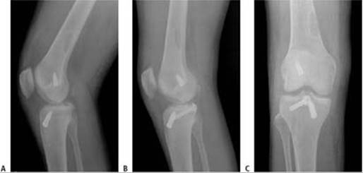
TECH FIG 10 • A. PCL tibial avulsion in a patient with a previous ACL reconstruction. B,C. Lateral and PA radiographs after fixation of the tibial avulsion.

POSTOPERATIVE CARE
 A hinged knee brace is applied and locked in extension. The patient is awakened and taken to the recovery room, where pain and neurovascular status are reevaluated.
Patients may be kept overnight for pain management and to monitor their neurovascular status.
Patients are given instructions for exercises (quadriceps sets, straight-leg raises, and calf pumps) and crutch use.
All dressing changes are performed while an anterior tibial force is applied.
Patients are instructed to maintain touch-down weight bearing for 1 week.
Partial weight bearing is initiated after the first postoperative visit.
The brace is unlocked after 4 to 6 weeks, and usually is discontinued after 8 weeks.
Symmetric full hyperextension is achieved, and passive prone knee flexion, quadriceps sets, and patellar mobilization exercises are performed with the assistance of a physical therapist for the first month.
Mini-squats are performed from 0 to 60 degrees after the first week and from 0 to 90 degrees after the third week.
Once full, pain-free ROM is achieved, strengthening is addressed.
The goals for achievement of flexion are 90 degrees at 4 weeks and 120 degrees at 8 weeks.
OUTCOMES
Choice of graft (autograft vs allograft) has not been shown to affect overall outcome.3
Acute single-bundle reconstructions have been demonstrated to have significantly better outcomes than chronic reconstructions.12
The clinical outcomes after single-bundle and tibial inlay reconstructions have produced a satisfactory return of function and improvement in symptoms.3,12
Neither transtibial or tibial inlay has been shown to be superior with regard to overall outcome.7
No studies have specifically addressed the long-term clinical outcomes of double-bundle reconstructions and PCL augmentation reconstructions.
COMPLICATIONS
Failure to carefully position the extremity with adequate padding may result in neuropraxia.
Loss of motion (usually decreased flexion) can result from errors in graft positioning or excessive tensioning during graft fixation. Inadequate rehabilitation also may lead to loss of motion.
Residual laxity also can occur as a result of graft positioning or failure to address concomitant ligamentous injury.
Injury to the popliteal vessels is rare, but may be a very serious complication. Care must be taken to prevent overpenetration of the posterior tibial cortex.
The thigh and calf should be routinely palpated to ensure no compartment syndrome develops from fluid extravasation into the soft tissues.
REFERENCES
1. Ahn JH, Ha CW. Posterior trans-septal portal for arthroscopic surgery of the knee joint. Arthroscopy 2000;16:774–779.
2. Ahn JH, Yoo JC, Wang JH. Posterior cruciate ligament reconstruction: double-loop hamstring tendon autograft versus Achilles tendon allograft: clinical results of a minimum 2-year follow-up. Arthroscopy 2005;21:965–969.
3. Cooper DE, Stewart D. Posterior cruciate ligament reconstruction using single-bundle patella tendon graft with tibial inlay fixation: 2to 10-year follow-up. Am J Sports Med 2004;32:346–360.
4. Giffin JR, Vogrin TM, Zantop T, et al. Effects of increasing tibial slope on the biomechanics of the knee. Am J Sports Med 2004;32:376–382.
5. Harner CD, Waltrip RL, Bennett CH, et al. Surgical management of knee dislocations. J Bone Joint Surg Am 2004;86A:262–273.
6. Kim SJ, Park IS. Arthroscopic reconstruction of the posterior cruciate ligament using tibial-inlay and double-bundle technique. Arthroscopy 2005;21:1271.
7. MacGillivray JD, Stein BE, Park M, et al. Comparison of tibial inlay versus transtibial techniques for isolated posterior cruciate ligament reconstruction: minimum 2-year follow-up. Arthroscopy 2006;22: 320–328.
8. Margheritini F, Mancini L, Mauro CS, et al. Stress radiography for quantifying posterior cruciate ligament deficiency. Arthroscopy 2003; 19:706–711.
9. Mariani PP, Margheritini F. Full arthroscopic inlay reconstruction of posterior cruciate ligament. Knee Surg Sports Traumatol Arthrosc 2006;14:1038–1044. Epub 2006 Sep 8 2006.
10. Mauro CS, Margheritini F, Mariani PP. The arthroscopic transeptal approach for pathology of the posterior joint space. Tech Knee Surg 2005;4:120–125.
11. Parolie JM, Bergfeld JA. Long-term results of nonoperative treatment of isolated posterior cruciate ligament injuries in the athlete. Am J Sports Med 1986;14:35–38.
12. Sekiya JK, West RV, Ong BC, et al. Clinical outcomes after isolated arthroscopic single-bundle posterior cruciate ligament reconstruction. Arthroscopy 2005;21:1042–1050.
13. Shelbourne KD, Davis TJ, Patel DV. The natural history of acute, isolated, nonoperatively treated posterior cruciate ligament injuries. A prospective study. Am J Sports Med 1999;27:276–283.
14. Toritsuka Y, Horibe S, Hiro-Oka A, et al. Conservative treatment for rugby football players with an acute isolated posterior cruciate ligament injury. Knee Surg Sports Traumatol Arthrosc 2004;12:110–114.