
Beat Hintermann and Alexej Barg
DEFINITION
 The HINTEGRA Total Ankle Prosthesis (Integra, Plainsboro, NJ) is an unconstrained, three-component system that provides inversion–eversion stability (FIG 1). Axial rotation and normal flexion–extension mobility are provided by a mobile bearing element.3,6
The HINTEGRA ankle includes a metal tibial component, an ultrahigh-density polyethylene mobile bearing, and a metal talar component, all of which are available in six sizes. The metal components are manufactured of cobalt–chromium alloy with a porous coating of a 20% porosity. The porous coating is covered by titanium fluid and hydroxyapatite. The remaining metallic surfaces are highly polished.
The tibial component employs a flat, 4-mm-thick loading plate with pyramidal peaks on the flat surface against the tibia and an anterior shield that allows for fixation by two screws through two oval holes. The anatomically sized flat surface allows for optimal contact with the subchondral bone, as well as optimal support of the cortical bone ring, providing a maximal load-transfer area. It also makes it possible to minimize bony resection to 2 to 3 mm of the subcortical bone. This fixation concept prevents any stress shielding from occurring.
The talar component is conically shaped, with a smaller radius medially than laterally. It consists of a highly polished articular surface, and a medial and lateral surface. A 2.5mm-high rim on the medial and lateral sides ensures stable position and anteroposterior translation of the polyethylene on the talar surface. The medial and lateral talar surfaces are covered by two wings that are anatomically sized and formed to the original articular, cartilage-covered surfaces. The inner, slightly curved surface of the wings allows for press-fit of the component to the bone. The anterior shield increases the bone support on weaker bone at the talar neck to increase stability in the sagittal plane and to prevent the adherence of scar tissue that might restrict motion. The current design, introduced in 2004, includes two pegs to facilitate the insertion of the talar component and to provide additional stability.
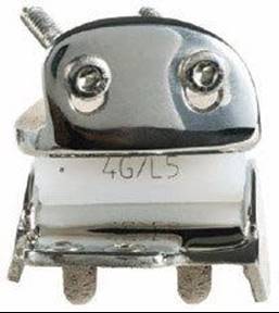
FIG 1 • The HINTEGRA ankle consists of three components.
The high-density polyethylene mobile bearing (ultrahighmolecular-weight polyethylene) consists of a flat surface on the tibial side and a concave surface that perfectly matches the talar surface. It has a minimum thickness of 5 mm but is also available for thicker sizes (6, 7, and 9 mm). The size of the bearing is determined by the talar size. As it fully covers the talar component, it ensures optimal stability against valgus–varus forces and minimal contact stress in both the primary and secondary articulating surfaces. The bearing is restrained by the compressive action of the collateral ligaments and adjacent tissues. Further, compressive muscle forces and gravitational loads across the joint hold the bearing against the metallic articulating surfaces. Thus, when properly positioned, dislocation of the bearing is unlikely.
The HINTEGRA ankle provides 50 degrees of congruent contact flexion–extension and 50 degrees of congruent contact axial rotation, which provides congruent contact surfaces for normal load-bearing activities, even in the case of a distinct implantation error or pre-existing deformity. Limits of motion depend on natural soft tissue constraints: no mechanical prosthetic motion constraints are imposed for any ankle movement with this device.
The HINTEGRA ankle uses all available bone surface for support. The anatomically shaped, flat tibial and talar components essentially resurface the tibia and talar dome, respectively, and the wings hemiprosthetically replace degenerate medial and lateral facets (a potential source of pain and impingement).
ANATOMY
The superior extensor retinaculum is a thickening of the deep fascia above the ankle, running from tibia to fibula.
It includes, from medially to laterally, the tendons of tibialis anterior, extensor hallucis longus, and extensor digitorum longus.
The anterior neurovascular bundle lies roughly halfway between the malleoli; it can be found consistently between the extensor hallucis longus and extensor digitorum longus tendons.
The neurovascular bundle contains the A. tibialis anterior and the deep peroneal nerve. The nerve supplies the extensor digitorum brevis and extensor hallucis brevis and a sensory space interdigital I–II.
On the height of the talonavicular joint the medial branches of the superficial peroneal nerve cross from lateral to medial. It supplies the skin of the dorsum of the foot.
On the posterior aspect of the ankle, the medial neurovascular bundle is located behind its posteromedial corner and the flexor hallucis longus tendon on its posterior aspect. The deltoid ligament is a multibanded complex with superficial and deep components.
PATHOGENESIS
Primary osteoarthritis of the ankle joint is rare; degenerative disease of the ankle is more often seen after trauma and systemic diseases (eg, rheumatoid arthritis).
Osteoarthritis of the ankle joint is often associated with malalignment, deformities, and instabilities of the foot, particularly in posttraumatic ankles.5
NATURAL HISTORY
Development of osteoarthritis of the ankle joint can take years, particularly in posttraumatic ankles (eg, after fractures and sprains).
Once it has become symptomatic, osteoarthritic changes usually progress, resulting in pain under loading and finally at rest.
If associated with instability or muscular dysfunction, misalignment and deformity may occur.
PATIENT HISTORY AND PHYSICAL FINDINGS
A careful history is taken to assess:
 Previous trauma
Previous infections
Underlying diseases
Actual pain
Limitations in daily and sports activities
While the patient is standing, a thorough clinical investigation of both lower extremities is done to assess:
Alignment
Deformities
Foot position
Muscular atrophy
While the patient is sitting with free-hanging feet, the examiner assesses:
The extent to which a deformity is correctable
Preserved joint motion at the ankle and subtalar joints
Ligament stability of the ankle and subtalar joints with anterior drawer and tilt tests
Supination and eversion power (eg, function of posterior tibial and peroneus brevis muscles)
IMAGING AND OTHER DIAGNOSTIC STUDIES
Plain weight-bearing radiographs, including AP views of the foot and ankle and a lateral view of the foot (FIG 2), are obtained to assess:
Extent of destruction of the tibiotalar joint (eg, tibia, talus, and fibula)
Status of neighboring joints (eg, associated degenerative disease)
Deformities of the foot and ankle complex (eg, heel alignment, foot arch, talonavicular alignment)
Tibiotalar malalignment (eg, varus, valgus, recurvatum, and antecurvatum)
Bony condition (eg, avascular necrosis, bony defects)
A CT scan may be ordered for assessment of:
Destruction of joint surfaces and incongruency
Bony defects
Avascular necrosis
Single-photon-emission computed tomography combined with computed tomography (SPECT-CT) with a superimposed bone scan (FIG 3) may be used to visualize:
Morphologic pathologies and associated activity process
Biologic bone pathologies and associated activity process
MR imaging may be used to show:
Injuries to ligament structures
Morphologic changes of tendons
Avascular necrosis of bones (eg, talar body and tibial plafond)
Gait analysis7

FIG 2 • Preoperative assessment includes weight-bearing standard radiographs as follows: (A) AP view of the ankle; (B) lateral view of the foot; (C) AP view of the foot.

FIG 3 • Single photon emission computed tomography with combined computed tomography (SPECT-CT) in a patient with valgus deformity showing the pathologic process in the lateral tibiotalar and fibulotalar joints. A. AP view. B. Lateral view.
NONOPERATIVE MANAGEMENT
Although nonoperative management is controversial, patients with less debilitating pain and dysfunction may be treated nonoperatively.
Nonoperative treatment may consist of:
Shoe modifications to facilitate gait
Physiotherapy to decrease inflammatory response
Anti-inflammatory medicine for acute pain
SURGICAL MANAGEMENT
Successful total ankle arthroplasty with an unconstrained three-component prosthesis demands thorough preoperative planning to address all associated pathologies.
During surgery, the surgeon must continuously check whether these associated pathologies are sufficiently addressed. For instance:
Whether pre-existing deformity is sufficiently corrected
Whether the foot is properly aligned
Whether soft tissues are sufficiently balanced
Indications
Primary osteoarthritis (eg, degenerative disease)
Systemic arthritis (eg, rheumatoid arthritis)
Posttraumatic osteoarthritis (if instability and malalignment are manageable)
Secondary osteoarthritis (eg, infection, avascular necrosis) (if at least two thirds of the talar surface is preserved)
Salvage for failed total ankle replacement (if bone stock is sufficient)
Salvage for nonunion and malunion of ankle fusion (if bone stock is sufficient)
Low demands for physical activities (hiking, swimming, biking, golfing)
Relative Indications
Severe osteoporosis
Immunosuppressive therapy
Increased demands for physical activities (eg, jogging, tennis, downhill skiing)
Bony avulsion fracture of medial malleolus (with or without fracture of the fibula–syndesmotic disruption)
Contraindications
Infection
Avascular necrosis of more than one third of the talus
Unmanageable instability
Unmanageable malalignment
Neuromuscular disorder
Neuroarthropathy (Charcot)
Diabetic syndrome
Suspected or documented metal allergy or intolerance
Highest demands for physical activities (eg, contact sports, jumping)
Controversial Indications
Diabetic syndrome without polyneuropathy
Avascular necrosis of talus
Preoperative Planning
All imaging studies are reviewed.
Plain films should be reviewed to identify possible coexisting arthritis of adjacent joints as well as varus and valgus of the hindfoot and the longitudinal arch.
Associated foot deformity, malalignment, and instability should be addressed concurrently.
Examination under anesthesia should be accomplished to compare with the contralateral ankle.
Positioning
The patient is positioned with the feet on the edge of the table.
The ipsilateral back is lifted until a strictly upward position of the foot is obtained.
A block is placed under the affected foot to facilitate fluoroscopy during surgery.
The contralateral (nonaffected) leg is also draped if significant deformity is to be corrected.
A tourniquet is applied on the ipsilateral thigh.
Approach
An anterior longitudinal incision 10 to 12 cm long is made to expose the retinaculum.
The retinaculum is dissected along the lateral border of the anterior tibial tendon, and the anterior aspect of the distal tibia is exposed.
While the soft tissue mantle is dissected with the periosteum from the bone, attention is paid to the neurovascular bundle that lies behind the long extensor hallucis tendon.
Capsulotomy and capsulectomy are done, and a self-retaining retractor is inserted to carefully keep the soft tissue mantle away (FIG 4).
Osteophytes on the tibia are removed, particularly on the anterolateral aspect.
Osteophytes on the talar neck and the anterior aspect of medial malleolus are also removed.
The fibula usually cannot be fully visualized at this stage.

FIG 4 • The ankle joint is exposed through an anterior approach.
TECHNIQUES
TIBIAL RESECTION
 Position the tibial cutting block with its alignment rod using the tibial tuberosity (eg the anterior cresta iliaca of pelvis in the case of leg deformity [TECH FIG 1A] as the proximal reference and the anterior border of the ankle (eg, the center of the resection block is supposed to be at intermediate line of the tibiotalar joint) as the distal reference.
Make the final adjustment as follows:
 Sagittal plane: Move the rod until a parallel position to the anterior border of the tibia has been achieved (TECH FIG 1B).
Frontal (coronal) plane: Frontal plane position is given by the position of the rod (eg there is a fixed 90° angle between the resection surface and the rod). Once the rod is proximally centered to tibial tuberosity (TECH FIG 1C), two pins are used for fixation.
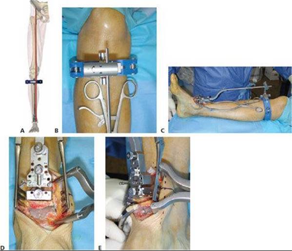
TECH FIG 1 • Tibial resection. A,B. Tibial resection block is adjusted taking the tibial tuberosity or the anterior spina of iliac crest as the reference in the frontal plane, and (C) the anterior tibia in the sagittal plane. D. 2 to 3 mm of bone is removed, as measured at the apex of the tibial plafond. E. Bone is removed and resection is finalized at the lateral side, paying attention to not damaging the integrity of the fibula and at the medial side to get a sharp perpendicular cut along the medial malleolus.
Vertical adjustment: Move the tibial resection block proximally until the desired resection height is achieved. Usually resection of about 2 to 3 mm on the apex of the tibial plafond is desired. In varus ankles more tibial resection is usually needed, whereas in valgus ankles or in presence of high joint laxity, less bone resection is advised.
Rotational adjustment: Rotate the tibial resection block to get a parallel position of its medial surface to the medial surface of the talus (eg, to avoid damaging the malleoli with the saw blade during resection).
Slide the tibial cutting guide into the cutting block, creating a slot in which the saw blade will be guided. The width of the slot limits the excursion of the saw blade, thereby protecting the malleoli from hitting and fracturing.
Once the tibial cut is made, a reciprocating saw might be used to finalize the cuts, particularly for the vertical cut on the medial side (TECH FIG 1D).
Remove the remaining bone with a rongeur (TECH FIG 1E), including the posterior capsule.
Use the measuring gauge to determine the size of the implant. In doubt (eg, if the anterior border of the tibia is projected onto the gauge between two markers), select the bigger size.
TALAR RESECTION
Insert the talar resection block into the tibial cutting block.
Move the resection block distally as much as possible to properly tension the collateral ligaments (TECH FIG 2A).
Remove all distractors and spreaders before the foot is taken into neutral position (eg, with respect to dorsiflexion–plantarflexion and pronation–supination).
Once the foot is in neutral position, fix the resection block with two pins (medially and laterally) (TECH FIG 2B,C).
Resect the talar dome with the oscillating saw through the slot of the talar cutting block.
Remove the tibial and talar resection block and again mount the distractor (Hintermann spreader) to distract the joint.
Remove the posterior capsule completely until fat tissue and tendon structures are visible to achieve full dorsiflexion.
Insert the 12-mm-thick spacer representing the thickness of the tibial and talar components and the thinnest 5-mm inlay into the created joint space (TECH FIG 2D). While the foot is held in neutral flexion position, this allows the surgeon to check:
Whether an appropriate amount of bone has been resected
 Whether the achieved alignment is appropriate
Whether the medial and lateral stability are approximate
If the spacer cannot be properly inserted into the joint space, and if there is no obvious contracture of the remaining posterior capsule present, additional bony resection might be considered. In most instances, such additional resection should be done on the tibial side. Reposition the tibial cutting block using the same fixation holes for the pins. Move the distal resection block proximally as desired, and make a new cut with the saw blade.
If the alignment is not appropriate, and if an associated deformity of the foot itself (eg, varus, valgus heel) can be excluded, consider a corrective cut. In most instances, the resection should be done on the tibial side. Make the desired angular correction on the tibial resection block, and reposition the tibial cutting block using other fixation holes for the pins. Move the distal resection block proximally or distally so that an angular bony resection will result.


TECH FIG 2 • Talar resection. A. After insertion of talar resection block, the whole block is moved distally until collateral ligaments of ankle are fully tensioned. B. Talar resection block is fixed by pins to the talus while the foot is held in neutral position. C. Alignment of the hindfoot is carefully checked. D. After the horizontal cut is made by the saw through the slot and the resection block is removed, the spacer is inserted to check alignment and stability of the ankle. E. Appropriate size of talar resection block is fitted to the bone using the medial border of the talus as the reference. F. After posterior, medial, lateral and anterior cuts are made, the block is removed. G. Bone stock of talus after careful debridement of the medial, lateral, and posterior compartment as well as complete resection of the posterior capsule of the ankle joint.
If the ankle is not stable on both sides, consider using a thicker inlay. If the ankle is not stable on one side, consider a release of the contralateral ligaments or ligament reconstruction on the affected side. Ligament reconstruction is better done once the definitive implants have been inserted, and if there is still an obvious instability.
Remove the spacer and mount the distractor (Hintermann spreader) using the same pins.
Determine the size of the resected talar block as follows (TECH FIG 2E):
Use the medial side of the talus as the reference; position the resection block along the medial border of the talus so that 1 to 2 mm of bone will be removed from the medial side of the talus.
On the lateral side, the resection block is supposed to remove as little bone as possible on its posterior aspect; usually, more bone will need to be removed on the lateral aspect of the talus as there are osteophytes.
On the posterior side, the resection block is supposed to remove 2 to 3 mm of bone in addition to remaining cartilage; this is given by the distance of the posterior hooks of resection block that aim to be in strong contact with the posterior surface of talus.
The talar size should not exceed the previously determined tibial component by more than one size; if so, a smaller talar size must be selected.
After selecting the appropriate size of talar cutting block, fix it with two or three short pins.
Make posterior resection on the talus with an oscillating saw that is guided through the posterior slot of the talar cutting block.
Make medial and lateral resections on the talus with a reciprocating saw that is guided along the talar cutting block. Make the cut as follows:
Medial side: 6 mm deep; the reference is the upper surface of the talus
Lateral side: 8 mm deep; the reference is the upper surface of the talus
Make the anterior resection on the talus with a drill that is guided through the anterior slot of the talar cutting block.
Remove the talar cutting block (TECH FIG 2F)
On the medial and lateral sides, the cuts are finalized by using a chisel to make an almost horizontal cut along the base of the cuts previously made, thereby avoiding extended loss of bone stock and potential damage to the vascular supply of the talus.
Clean the medial and lateral gutters using a rongeur.
Remove the remaining bone and capsule of the posterior compartment (TECH FIG 2G).
INSERTING TRIAL IMPLANTS AND FINALIZING CUTS
Talar trial:
Insert the talar trial using the given impactor. The window on the posterior aspect of the trial allows the surgeon to check its proper fit to the posterior resection surface of the talus (TECH FIG 3A)
If proper position of the talus has been achieved, resect the anterior surface of the talus using a rongeur or the oscillating saw.
Fix the drill guide onto talar trial (TECH FIG 3B)
Make two drill holes with the provided 4.5-mm drill, and remove the trial (TECH FIG 3C).
Tibial trial:
Use the tibial depth gauge to determine the size of tibial implant to be selected; insert it with the appropriate side (right/left) against the tibial surface, and hook the posterior edge on the posterior border of the tibia. The size to be selected can be taken from the scale on the depth gauge (TECH FIG 3D).
Remove the depth gauge and, if necessary, smooth the anterior border of tibia resection with an oscillating saw or rongeur according to the shape of indicated resection.
Insert the tibial trial. Try to get the tibial component in close contact with the medial malleolus and the anterior surface of tibia (TECH FIG 3E).
Trial inlay: Insert the 5-mm inlay trial and remove the distractor (Hintermann spreader); if not enough soft tissue tension can be achieved, insert the 6-mm, 7-mm, or 9-mm trial.
The use of fluoroscopy is highly recommended to check the position of implants while the foot is held in neutral position, particularly:
Appropriate length of the tibial component: its posterior border should be on line with the posterior aspect of the tibia so that the tibial surface is fully covered
Proper fit of the tibial component to the tibial surface
Proper fit of the posterior edge of the talar component to the posterior surface of the talus
Point of contact of the talar component to the tibial component. This contact point should be between 40% and 45% of the tibial component when the anterior border is taken as 0% and the posterior border as 100%, respectively. If the point of contact is too posterior, ligament balance will not be achieved.
Carefully check the bony surfaces. Any cysts are removed with a curette, and filling with cancellous bone taken from the removed bony material is recommended. If there is sclerotic bone left on surface, drilling with a 2.0-mm drill is recommended.

TECH FIG 3 • Trial implants. A. First, the trial implant of the talus is inserted, paying attention to obtain a proper fit to the posterior resection surface. B. After resection of anterior surface, the bloc is inserted and the holes for the pegs are drilled. C. The talar trial is removed. The resection surfaces of the talus and tibia are carefully checked for cyst formations. If present, they are meticulously removed. D.The tibial depth gauge is inserted and the size of tibial implant is determined. E. The tibial trial implant is inserted paying attention to get the tibial component in close contact with the medial malleolus and the anterior surface of tibia. If necessary, the anterolateral tibia has to be smoothed.
INSERTION OF IMPLANTS
Insert the final implants, as previously selected, as follows:
Fill the talar component with bone matrix (ISOTIS) to get the cysts filled and then insert it such as the pegs can glide into the two drilled holes; use a hammer and impactor to obtain a proper fit of the component to the bone (TECH FIG 4A).
Insert the tibial component along the medial malleolus until proper fit to the anterior border of the tibia is achieved (TECH FIG 4B).
Insert the inlay (same size as the talar component). Remove the distractor (Hintermann spreader). Hammer and impactor might be used for appropriate fit to bone (TECH FIG 4C).
Check stability and motion clinically.
While the foot is moved in dorsiflexion with the surgeon's maximal power, settling of the implant might be improved, and remaining soft tissue contracture on the posterior aspect of the ankle might be released (TECH FIG 4D).
Screw fixation of the tibial component may be considered to achieve stability against rotational and translational forces during the osteointegration process; however, this is very seldom necessary as the proper fit and pyramidal peaks do provide sufficient primary stability.
It is also highly recommended to check the position of the implants by fluoroscopy, as described for the trial implants (TECH FIG 4E,F). This also allows the surgeon to detect any remaining bony fragments or osteophytes that could be a potential source of pain or motion restriction.
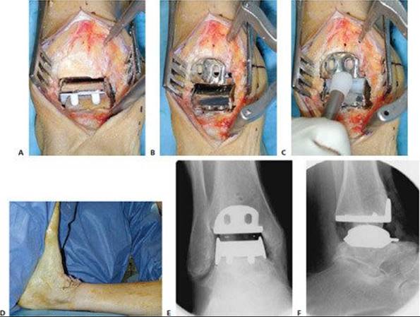
TECH FIG 4 • Insertion of definitive implants. A. The talar component is impacted first. B. After insertion of the tibial component and the polyethylene insert (C), the tibial component is impacted to obtain a proper fit to the tibial resection surface. D. The foot is moved in dorsiflexion with the surgeon's maximal power, thereby settling of the implant might be improved, and remaining soft tissue contracture on the posterior aspect of the ankle might be released. E. Final check of the position of the implants using fluoroscopy. On the AP view the surgeon checks the position of the implants for any misalignment that may cause edge load of the polyethylene insert, overall alignment in the frontal (coronal) plane, distraction of the ankle (gap between the fibula and talus), and medial and lateral gutters for any bone left that may cause bony impingement. F. On the lateral view the surgeon checks the position of the implants with regard to the bone surfaces (proper fit) and alignment of the implants with regard to contact area (usually, the apex of the talar component should meet the tibial component 3 to 5 mm anterior to its midpoint).
WOUND CLOSURE
The wound is closed by suturing the tendon sheath and retinaculum (TECH FIG 5A) and the skin (TECH FIG 5B).
Dress the wound, taking care to avoid any pressure to the skin (TECH FIG 5C).
A splint is used to keep the foot in neutral position (TECH FIG 5D).

TECH FIG 5 • Wound closure and dressing. A. The extensor retinaculum is closed first. B. Then, the skin is closed by interrupted sutures. C. A compressive dressing is used to avoid swelling and hematoma formation. D. A splint is used to keep the foot in neutral position.

POSTOPERATIVE CARE
The dressing and splint are removed and changed after 2 days.
When the wound is dry and proper, typically 2 to 4 days after surgery, the foot is placed in a stabilizing cast or walker that protects the ankle against eversion, inversion, and plantarflexion movements for 6 weeks.
Active motion and lymphatic drainage may support recovery of soft tissues during the first 6 weeks. Overly aggressive motion during the first postoperative days, however, may lead to breakdown of soft tissues.
Weight bearing is allowed as tolerated. Usually, full weight bearing is achieved after 1 week.
In the case of additional osteotomies of the calcaneus, ligament reconstruction, or tendon transfer, cast immobilization for 6 weeks is advised.
In the case of additional fusion of adjacent joints, cast immobilization for 8 weeks is advised.
In the case of additional supramalleolar osteotomy, the patient should remain non–weight-bearing for 8 to 10 weeks.
A rehabilitation program should be started for the foot and ankle after cast or walker removal, including stretching and strengthening of the triceps surae.8
First clinical and radiologic follow-up is made at 6 weeks, to check the wound site and osteointegration and position of the implants.
The patient should be advised to wear a compression stocking to avoid swelling for a further 4 to 6 months.
OUTCOMES
Between May 2000 and December 2006, 574 primary total ankle arthroplasties were performed in 549 patients (272 women, 277 men; mean age 59.7 ± 12.6 years [range 19.8 to 90 years]; left side 277, right side 297, bilateral 26). The underlying diagnosis was posttraumatic osteoarthritis in 459 ankles, primary osteoarthritis in 40 ankles, and inflammatory arthritis in 63 ankles.
The mean follow-up was 31.9 ± 19.7 months (range 12 to 82 months). The mean AOFAS improved from 42.1 ± 17.0 preoperatively to 78.1 ± 11.1 postoperatively, and the mean pain relief was from 6.8 ± 3.9 preoperatively to 2.9 ± 2.4 postoperatively. The mean plantarflexion at latest follow-up was 28.5 ± 10.2 degrees and the mean dorsiflexion was 6.4 ± 6.1 degrees. The satisfaction grade was excellent in 213 patients (38.8%), good in 238 patients (43.4%), and moderate in 87 patients (15.8%); only 11 patients (2.0%) were dissatisfied.
Early complications included malleolar fractures intraoperatively, 11 patients; wound healing problems, 7 patients; infection, 4 patients; and polyethylene dislocation, 5 patients.
Late complications included loosening of components, 24 patients (talar component, 22 patients, 7 of them with subsidence or migration; tibial component, 19 patients, none of them with subsidence or migration); polyethylene dislocation, 5 patients; polyethylene wear, 0; progressive loss of motion, 38 patients; chronic pain syndrome, 11 patients.
Taking revision of a metallic implant or conversion into ankle arthrodesis as the endpoint, overall survivorship of both components at 6 years was 98.2% (97.9% for the talar component and 98.8% for the tibial component).
Four ankles were revised to total ankle arthroplasty (component loosening, three; pain, one), and two ankles (component loosening and recurrent misalignment, one; pain, one) were revised to ankle arthrodesis.
COMPLICATIONS
Intraoperative complications1–4
Malpositioning of prosthetic implant
Improper sizing of prosthetic implant
Fractures of malleoli
Tendon injuries
Postoperative complications1–4
Wound healing problems
Infection
Swelling
Deep venous thrombosis
Late complications1–4
Aseptic loosening
Subsidence
Polyethylene wear
Dislocation of polyethylene insert
Progressive loss of motion
REFERENCES
· Haddad SL, Coetzee JC, Estok R, et al. Intermediate and long-term outcomes of total ankle arthroplasty and ankle arthrodesis: a systemic review of the literature. J Bone Joint Surg Am 2007;89A:1899–1905.
· Henricson A, Skoog A, Carlsson A. The Swedish ankle arthroplasty register: an analysis of 531 arthroplasties between 1993 and 2005. Acta Orthop 2007;78:569–574.
· Hintermann B, Valderrabano V, Dereymaeker G, et al. The HINTEGRA ankle: rationale and short-term results of 122 consecutive ankles. Clin Orthop Relat Res 2004;424:57–68.
· SooHoo NF, Zingmond DS, Ko C. Comparison of reoperation rates following ankle arthrodesis and total ankle arthroplasty. J Bone Joint Surg Am 2007;89A:2143–2149.
· Valderrabano V, Hintermann B, Horisberger M, et al. Ligamentous posttraumatic ankle osteoarthritis. Am J Sports Med 2006;34:612–620.
· Valderrabano V, Hintermann B, Nigg BM, et al. Kinematic changes after fusion and total replacement of the ankle. Part 1: Range of motion. Part 2: Movement transfer. Part 3: Talar movement. Foot Ankle Int 2003;24:881–900.
· Valderrabano V, Nigg BM, von Tscharner V, et al. Gait analysis in ankle osteoarthritis and total ankle replacement. Clin Biomech 2007;22:894–904.
· Valderrabano V, Pagenstert G, Horisberger M, et al. Sports and recreation activity of ankle arthritis patients before and after total ankle replacement. Am J Sports Med 2006;34:993–999.