
John M. Rhee, Claude Jarrett, and Sam W. Wiesel
DEFINITION
 Cervical spondylosis refers to degenerative conditions affecting the cervical spine, including disc degeneration, herniation, facet arthrosis, and osteophytic spur formation. Depending on the nature and location of the spondylotic changes, pathologic compression of neural structures in the cervical spine may occur.
This chapter focuses on anterior cervical discectomy and fusion (ACDF) as a surgical treatment option for patients with cervical radiculopathy. Cervical myelopathy can also be treated with ACDF as long as the spinal cord compression occurs at the disc, rather than the retrovertebral, level.
All techniques described in this chapter can apply to the decompression of the spinal cord in myelopathic patients as well as the nerve root in radiculopathic patients. However, for the purposes of organization, cervical myelopathy is discussed in the chapter on anterior cervical corpectomy (see Chap. SP-7).
ANATOMY
The anterior longitudinal ligament is a wide band of ligaments stretching along the anterior surface of the vertebral bodies. Its dense longitudinal fibers widen as they travel caudally and are intimately associated with the intervertebral discs as well as the vertebral endplates.
The posterior longitudinal ligament (PLL) is a smooth and shiny group of dense ligaments that course along the posterior surface of the vertebral bodies within the spinal canal. The PLL tends to be thicker centrally and thins out laterally as it attaches to the uncinate regions. Bulging or ossification of the PLL (OPLL) can cause spinal cord compression.
The intervertebral disc comprises the outer annulus fibrosus and the central gelatinous nucleus pulposus. Each disc is attached to the subchondral bone of the adjacent vertebral bodies. The outermost rim of the vertebral endplate is not attached to the disc, leaving a ring of exposed bone that may be more prone to forming arthrotic spurs.
The uncovertebral joints are critical bony landmarks for anterior cervical decompression (FIG 1). Spurs commonly arise from these articulations and cause impingement of the exiting roots as they enter the foramen.
 Depending on the cervical level, the vertebral artery may be as close as 5 mm away from the medial aspect of the uncinate process.
Each cervical spinal nerve is composed of dorsal and ventral roots. The ventral root lies dorsal to the uncovertebral joint, while the dorsal root is ventral to the superior articular facet.
It is important to keep in mind when performing uncovertebral osteophyte resection that the nerve root leaves the spinal cord at roughly a 45-degree angle ventrolaterally in the axial plane. Thus, care must be taken to hug the posterior surface of the uncinate to avoid injury to the exiting root.4

FIG 1 • Anterior foraminotomy anatomy: important anatomic relationships to consider when performing anterior cervical spine surgery. The exiting nerve root enters the foramen at a 45-degree ventrolateral angle. The posterior aspect of the uncinate joint marks the entry zone of the neuroforamen, and it is where osteophytes commonly arise to impinge the exiting root. Thus, the uncus should be decompressed when performing foraminotomy. It is critical to hug the posterior aspect of the uncinate during foraminotomy to avoid injuring the exiting root, which lies immediately dorsal. The vertebral artery is unlikely to be injured while working in the posterior disc space (eg, during decompression) because it is located at roughly the level of the middle third of the vertebra. The trajectory of discectomy should be bounded by the uncinates at all times, but it can widen posteriorly at the level of the nerve root to thoroughly decompress the root while avoiding vertebral artery injury (dashed blue line). The posterior longitudinal ligament (dashed yellow line) tends to be thicker and better defined centrally; it thins out laterally.

PATHOGENESIS
Neural impingement occurs in two main locations: within the spinal canal, affecting the spinal cord, the nerve root, or both; or within the foramen, where the exiting root can be affected.
Depending on whether the involved structure is the spinal cord or the nerve root, patients can present with symptoms of myelopathy, radiculopathy, or both.
NATURAL HISTORY
The natural history of cervical radiculopathy is generally favorable, with most patients having spontaneous resolution or considerable improvement of their symptoms over time.
It is not common for radiculopathic patients to progress to myelopathy.9,10
HISTORY AND PHYSICAL FINDINGS
Patients with radiculopathy typically present with radiating pain, paresthesia, or motor weakness (Table 1). However, the pattern of symptoms is not always dermatomal (FIG 2).
On examination, patients with radiculopathy may have motor, sensory, or reflex changes along the affected nerve root distribution. However, the neurologic examination findings may be normal.
Patients may express exacerbation of radicular pain with particular head positions (ie, head positions that narrow the size of the neural foramen, such as neck extension with rotation to the affected extremity).
This can be elicited by performing the Spurling test. The Spurling sign is very helpful in differentiating cervical radiculopathy from extraspinal causes, such as cubital or carpal tunnel syndromes, as reproduction of symptoms should occur only with a cervical source of compression.
IMAGING AND OTHER DIAGNOSTIC STUDIES
Plain radiographs, although of limited value in evaluating neural compression, remain a commonly acquired initial study and can be used to evaluate overall alignment, spinal instability, or bony pathology, including spur formation.
MRI is the modality of choice for evaluating neural compression.
CT-myelography provides outstanding resolution of bony and neural anatomy, but it is less appealing as it requires an invasive procedure. It is typically recommended for patients with contraindications for MRI (eg, prosthetic heart valve, pacemaker) or when MRI fails to provide sufficient detail.
If a high-quality MRI is available but questions remain regarding bony anatomy for the purposes of surgical planning, a noncontrast CT scan provides complementary information (eg, differentiating OPLL from disc herniation) (FIG 3).
DIFFERENTIAL DIAGNOSIS
Cervical radiculopathy
Cervical myelopathy
Brachial plexus injury
Complex regional pain syndrome or reflex sympathetic dystrophy
Thoracic outlet syndrome
Inflammatory arthropathy
Spinal cord tumor
Angina

FIG 2 • Dermatomes of the cervical nerve roots. Symptoms do not always follow the textbook distribution of dermatomes. In particular, radiculopathies involving various nerve roots, such as C5, C6, or C7, can all produce periscapular pain, not uncommonly in the absence of radiating pain down the arm. If in doubt as to the offending level, a selective nerve root block can be performed for diagnostic purposes.

FIG 3 • MRI and CT scans may provide complementary information in delineating bony versus soft tissue masses. A. On the axial MRI, the compressive lesion appears to be a soft disc. B. A CT scan through the same level, however, demonstrates the pathology to be an ossified disc. Similarly, CT scans can help differentiate disc herniations from ossification of the posterior longitudinal ligament.
Shoulder pathology
Peripheral nerve compression (eg, carpal or cubital tunnel syndrome)
Diabetic neuropathy
Multiple sclerosis
Syringomyelia
Stroke
Guillain-Barré syndrome
Normal-pressure hydrocephalus
Spinal cord tumor
NONOPERATIVE MANAGEMENT
Nonoperative management should be considered as the initial mode of treatment for most patients with radiculopathy.
Nonsurgical treatment typically includes physical therapy, traction, pain medication, cervical collars, and epidural injections.
SURGICAL MANAGEMENT
Surgical intervention is indicated for radiculopathy in patients with persistent symptoms resistant to nonoperative care, progressive weakness, or instability.
Common surgical approaches to radiculopathy include ACDF versus posterior laminoforaminotomy.11
Preoperative Planning
The surgeon should evaluate imaging studies for anatomic variations, such as medial aberrancy of the vertebral artery.
To perform a safe but complete and adequate neural decompression, high-quality illumination and magnification are essential.
An operating microscope provides illumination and visualization superior to that of loupes and headlights, but either method can be used.
Another advantage to the microscope is that the view obtained by the assistant is the same as that of the operating surgeon.
If the surgeon chooses to use the microscope, given the smaller field of view, it is imperative to continuously adjust the viewing angle such that a line of sight parallel to the disc space is achieved (FIG 4). If this is not done, the surgeon may inadvertently stray away from the disc space, veer into one vertebral body or the other, and not proceed to the back of the disc space, where the decompression needs to occur.
Positioning
The patient is positioned with a bump under the scapula and the occiput on a foam doughnut to prevent pressure necrosis.
The amount of extension tolerated preoperatively without excessive pain or neurologic symptoms is recreated.
Approach
A standard Smith-Robinson approach to the anterior cervical spine is used for most cases from C2 to T2.

FIG 4 • Line of sight. When using the microscope, it must be angled properly to provide a parallel view of the disc space to facilitate decompression and endplate preparation. Endplate preparation should proceed in a parallel fashion (dotted red lines) (A) centered on the disc space to achieve a rectangular space for graft insertion. Parallel, wide preparation of the disc space also makes decompression easier to perform and ensures that the decompression is centered on the disc space (C). (B,C) If the line of sight is not maintained, one may err into the vertebral bodies above and below rather than progressing toward the area at the disc level that requires decompression. To achieve parallel surfaces, the inferior endplate of the cephalad vertebra typically requires greater preparation because it is concave. In contrast, the superior endplate of the caudal vertebra is flatter and requires less preparation. (C) Proper line of sight is facilitated by removing the anterior lip (arrow, shaded yellow), which allows for better visualization of, and access to, the posterior disc space.
TECHNIQUES
ANTERIOR CERVICAL DISCECTOMY AND FUSION WITH INSTRUMENTATION
Initial Discectomy
 Once the disc is exposed, it is sharply incised with a no. 15 blade and removed with a combination of curettes and pituitary rongeurs.
The disc and cartilaginous material should be removed until the PLL and both uncinate processes are visualized (TECH FIG 1A).
An important maneuver to facilitate disc space visualization and neural decompression is to remove the anterior portion of the inferior endplate of the superior vertebral body (the anterior lip). Doing so provides a direct line of sight into the posterior disc space, which facilitates later foraminotomy and resection of the PLL, if necessary.

TECH FIG 1 • A. The discectomy should begin lateral (red lines) to the medial border of the uncinates. The upslope of the uncinate is clearly defined with curettes and Kerrison rongeurs until these borders are unquestionably identified. Having a wide discectomy allows for placement of larger grafts or supplemental grafts in the uncinate regions. B,C. Anterior cervical discectomy and fusion graft carpentry. Creating parallel disc spaces facilitates graft–host bone contact, securing an intimate fit, as well as allowing for wide decompression of spurs arising from the posterior disc space. Spurs are removed off the inferior vertebrae of C5 and C6 (arrows). More bone than usual was removed from the inferior portion of C6 because of the extensive spondylotic bar causing spinal cord compression along the floor of the canal in this patient.
This surface is almost always concave, with the anterior portion overhanging the disc space, thus preventing direct visualization of the posterior disc space.
Removal can be done with either a Kerrison rongeur or a high-speed burr.
Flattening this surface also facilitates optimal graft–endplate contact (TECH FIG 1B,C).
Use of the burr to fashion the endplates, alternating with use of the curettes and pituitary rongeur to remove cartilage and disc material, is performed.
Use of Distraction: Pins, Tongs, and Spreaders
Intervertebral body distraction pins can be placed to gently distract the disc space and improve visualization.
 Generally, this is done after an initial superficial discectomy, which allows greater disc space mobilization with the pins.
Because greater preparation of the inferior endplate of the superior vertebra is usually needed, the Caspar pin should be placed more cephalad in the cephalad vertebral body (TECH FIG 2).
Overdistraction of the disc space is not desired. If the disc space is fused in an overdistracted position, postoperative neck pain may result. If there is a significant compressive lesion on the spinal cord, distraction should be avoided until the compression has been relieved to prevent stretching or tenting of the cord over that lesion.

TECH FIG 2 • Caspar pin placement. Because greater preparation of the inferior endplate on the cephalad vertebra is necessary, the surgeon should place the upper Caspar pin (C5) further away from the endplate (eg, in the midbody of C5 or more cephalad), while being cognizant of not entering the adjacent disc space above. The Caspar pins are placed in the midline to avoid compromising later screw fixation during plating. To achieve parallel distraction, the pins should be placed parallel to the disc space. If the tips (ie, the leading ends) converge, relative kyphosis of the disc space occurs with placement of the Caspar pin spreader and distraction; if the tips diverge, relative segmental lordosis occurs with placement of the Caspar pin spreader and distraction.
An additional benefit of the Caspar pins is that they help to retract the soft tissues in a cephalad–caudal direction without the use of a secondary set of retractor blades.
Alternatively, a small laminar spreader can be used in the contralateral disc space instead of Caspar pins to provide distraction.
Endplate Preparation
The inferior endplate of the cephalad level is concave, whereas the superior endplate of the inferior level tends to be relatively flatter. Thus, to achieve intimate contact of bone graft with both endplates, a rectangular space is created by parallel decortication of the endplates.
This generally requires greater preparation of the inferior endplate of the cephalad level versus the superior endplate of the inferior level.
It is important not to remove too much bone off the inferior endplate of the cephalad level, however, as doing so limits the bone available in the vertebra to accommodate a plate and screws. This is particularly the case in smaller patients who have smaller vertebrae.
A high-speed burr is helpful in decorticating the endplates.
The creation of a parallel rectangular space within the disc space allows insertion of a graft appropriately sized to match the larger height present at the center of the disc space.
Both endplates should be thoroughly denuded of cartilage and decorticated to reveal bleeding bony surfaces to enhance the chance of successful fusion.5
Alternating use of the high-speed burr, curettes, and the pituitary rongeur will allow the surgeon to reach the posterior disc space and the PLL.
During ACDF, we are more aggressive with endplate preparation than during corpectomy, because ACDF grafts tend to be more stable than corpectomy grafts.
If major endplate resection is performed during corpectomy, significant settling or pistoning of the graft may occur (see Chap. SP-7), which is less likely with ACDFs. Furthermore, in cases of extensive spondylosis, wide disc space preparation facilitates decompression along the floor of the canal in ACDF surgery.
When performing corpectomy, on the other hand, the additional room is not usually necessary because removing the vertebral body creates wide access for work at the disc level.
Anterior Foraminotomy
The discectomy is performed to the level of the PLL, with complete removal of the posterior annulus. It is safer to leave the PLL intact during the initial foraminotomy or resection of posterior osteophytes when the burr is being used, because it acts as a protective layer to the neural elements. Once the bony removal is complete, the PLL can then be resected.2
The medial half of the posterior uncinate is thinned under direct visualization with a high-speed burr to unroof the entry zone of the foramen (TECH FIG 3).
The microscope is angled appropriately to visualize the uncinate.

TECH FIG 3 • Anterior foraminotomy. A. The burr is used to thin down bone in the lateral aspect of the canal (arrow) until only a thin shell is left. The posterior longitudinal ligament (PLL) is left intact as a protective layer to the neural elements until burring is completed. B. A curette is used to outline the bony edges and ensure that they are thin enough for passage of a curette or Kerrison rongeur. The PLL does not necessarily need to be resected during foraminotomy if the pathology is due solely to uncinate bone spurs, although we routinely do so and do not consider the decompression complete until the lateral edge of the dura and the exiting root are clearly visualized and palpated to be free of compression. C. A 2-mm Kerrison is then used to remove bone spurs. It is critical to hug the posterior margin of the uncinate during this move to avoid injuring the root underneath, which exits the canal ventrolaterally at about a 45-degree angle.
In general, it is easier to decompress the contralateral rather than the ipsilateral foramen, although decompression of both is certainly possible. Thus, in cases of unilateral radiculopathy, we prefer to approach the spine from the side opposite to the patient’s symptoms.
It is important not to force a large instrument into a severely narrowed foramen if it does not fit easily. Instead, the surgeon should use the burr to thin the uncus until the instrument can easily be passed into the foramen.
Constant irrigation is performed to prevent thermal injury and to clear away bone debris.
If visualization is adequate, continued thinning of the osteophyte can progress until only a thin shell of bone is left.
A microcurette or 2-mm Kerrison is then used to resect the thinned osteophytes.
Alternating between microcurettes or a Kerrison and the burr, the foramen can be gently and progressively carved out laterally.
The nerve root exits the spinal canal at roughly a 45degree angle, ventrolaterally. Thus, it is imperative to avoid blindly placing a burr, curette, or Kerrison deep to the uncinate to avoid root injury. Instead, one should closely hug the uncinate while entering and decompressing the foramen (see Fig 1).
Foraminotomy is complete when a micro nerve hook or curette can easily be passed into the foramen anterior to the exiting root without resistance.6
When and How to Resect the PLL
With soft disc herniations, a defect in the PLL is often present through which the nuclear material extrudes (TECH FIG 4A,B).
By delicately probing with a microcurette, the extruded fragment can be fished out from behind the PLL.
If necessary, the defect in the PLL should be enlarged with a 2-mm Kerrison until a satisfactory portal is available to remove the herniation and ensure that all loose disc fragments have been removed.
It is debatable whether the PLL needs to be resected in every case. In general, we prefer to do so, especially in cases of disc extrusion, and do not consider the decompression complete until the dural sac or exiting nerve root (depending on which is compressed based on preoperative imaging) is inspected for the absence of any further compression.
If, however, the compressive lesion is an uncinate spur, with no evidence of subligamentous disc extrusion, satisfactory decompression can be achieved by removing the spurs without necessarily removing the PLL.
If there is no rent in the PLL, one can be created by teasing a microcurette between the longitudinal fibers of the PLL until the curette is posterior to the PLL (TECH FIG 4C,D).
Once the plane is identified between the PLL and dura, the fibers of the PLL can be resected with a curette or Kerrison rongeur.
Placing tension on the PLL with gentle distraction will facilitate its removal.
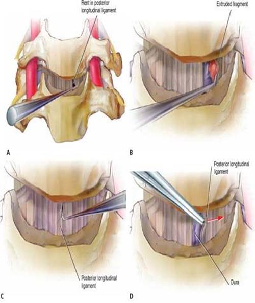
TECH FIG 4 A,B. • Removing herniated nucleus pulposus. A. With extruded herniations, a rent in the longitudinal fibers of the posterior longitudinal ligament (PLL) may be identified. A curette is then used to delineate the edges of the rent in the PLL. Once this is defined and the surgeon is certain of a plane between the PLL and underlying dura, a Kerrison is used to enlarge the edges of the rent. B. The rent has been enlarged to provide more room for finding the herniation. Curettes are then used to fish out the fragments and decompress the cord or root. C,D. Removing the PLL. C.If the PLL is intact, it can be removed by teasing in between the longitudinal fibers with a microcurette. Once a plane is established, a Kerrison can be used to remove the PLL. D. It is often easier to find this plane in the central portion of the PLL, where it is thicker, than laterally, where it is thinner and less defined.
We generally find it easier to define a plane in the PLL centrally, where it tends to be thicker, than laterally, where it is thinner and the plane with the dura is less distinct. Often, there are multiple layers of PLL, and usually in chronic cases there is a membranous layer between the PLL and the dural sac that can be confused with dura itself. In general, if it does not look like dura, it probably is not.
The portion of the PLL contralateral to the disc herniation or symptomatic foraminal stenosis does not routinely need to be removed.
Avoiding Vertebral Artery and Neural Injury
Before surgery, the surgeon should always scrutinize the position of the vertebral arteries on the preoperative scans to rule out the presence of aberrancies in their course (TECH FIG 5A,B,C).
Aberrations typically occur within the vertebral body. However, it is not uncommon for one vertebral artery to be closer to the uncinate on one side versus the other, which would mandate greater caution when approaching that side.3
In the absence of vertebral artery aberrancy, laceration to the vertebral artery is most likely to occur from the surgeon’s loss of orientation to the uncinates. The uncinates define the safe zone for the vertebral artery and the effective zone for the decompression.

TECH FIG 5 A,B. • Vertebral artery anomalies. A. The right transverse foramen (arrow) courses somewhat more medially than the one on the left. This is a subtle but potentially important anomaly to observe preoperatively. B. The anomaly occurs within the vertebral body rather than at the disc space level, where the right transverse foramen is now more normally positioned (arrow). C. Penfield lateral to the uncinate. In certain cases, especially if there is a deformity, the location of the lateral border of the uncinate (ie, the safe zone for the vertebral artery) may not be obvious after elevation of the longus colli. Placing a Penfield 4 dissector gently underneath the longus colli, retracting it laterally, and then hooking the dissector lateral to the uncinate will allow for safe orientation to the vertebral artery.
It is imperative to define and maintain orientation with both uncinates at all times during anterior cervical surgery.
The vertebral artery is typically in the anterior two thirds of the disc space. When curetting disc material in this area, a vertebral artery laceration might occur if the curette strays lateral to the lateral border of the uncinate.
If in doubt, a Penfield dissector can be used to identify the lateral border of the uncinate processes to avoid straying laterally and injuring the vertebral arteries, which are generally a few millimeters from the lateral edge of the uncinate (Tech Fig 5C).
Graft Sizing and Placement
Ultimate graft height can be estimated preoperatively from the preoperative lateral film. In many cases, a graft height of 2 to 3 mm more than that measured on the preoperative lateral film will be the optimal choice.
Ideally, the anteroposterior depth of the graft should be a few millimeters less than that of the disc space, such that the graft can be countersunk 2 mm without entering the spinal canal.
The final height of the graft can be determined after endplate preparation with sizers that accompany commercial grafts (TECH FIG 6).
The trials should be lightly malleted into position under gentle Caspar pin distraction.
A snug fit in the distracted position will ensure an excellent fit after removal of distraction pins.
If the trial does not fit but the next smaller trial seems too loose, the surgeon should identify the area of impingement and lightly decorticate that area. Then, the trial is reinserted.
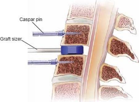
TECH FIG 6 • Commercially available sizers are used to determine optimal graft size. A trial that fits snugly under gentle Caspar distraction will suffice. If autograft is used, the appropriate trial is used as a template for cutting the autograft bone. The surgeon should try to place a graft that fills the space as much as possible without overdistracting, which can cause posterior neck pain, or entering the spinal canal.
For multilevel ACDF, we prefer to decompress and graft each segment before proceeding to the next level.
One way to enhance fusion rates is to place as much bone into the interspace as possible. A wide decompression also provides greater room for bone graft.
Space lateral to the structural bone graft in the uncinate regions can be packed with bone or bone graft substitutes. If the space is wide enough, two grafts can be placed side by side to fill the entire space.
We generally prefer to use commercially prepared cortical allografts for ACDF, except in patients with poor healing potential. Alternatively, autograft iliac crest bone can be used.
Determining Plate Length
Plating is optional for one-level ACDF with autograft. If allograft or multilevel surgery is performed, plating is recommended.
Once the graft has been placed, the size of the plate is then determined.
Optimal plate length is one that allows for the screws to be immediately adjacent to the endplates (TECH FIG 7).
This plate length allows for screws that angle away from the disc space, which in turn allows for screws that are longer than ones directed parallel to the disc space, yet are short enough to avoid entry into the supraand infra-adjacent disc spaces.
This length also prevents impingement of the plate into the adjacent disc spaces.
Plating Techniques
The plate should be contoured into lordosis to lie flush against the vertebral bodies.
It should also be centered coronally within the margins of the uncinate processes.
Screws should also be angled medially to decrease the chance of lateral injury to nerve roots or vertebral arteries.
The screw length can be estimated preoperatively by measuring the depth of the vertebral body on CT or MRI scans. The majority of levels will accommodate 14to 16mm screws.
Dynamic plates can be used if desired (TECH FIG 8). They have the theoretical benefit of improving load sharing on the graft. There are several types of dynamic plates.
Variable screw systems allow for toggling within a fixed screw hole with settling of the construct. A potential downside is that the screw can loosen within bone as toggling occurs.
Slotted plates have holes that allow screws to translate longitudinally as the construct shortens. The screws are rigidly fixed to bone and do not toggle, but excessive translation may lead to adjacent-level plate impingement.
Telescoping plates use fixed screws in nonslotted holes, but the ends of the plate telescope with respect to each other as settling occurs. Postoperative adjacent-level plate impingement will not occur with this design if the plate is properly positioned at the time of surgery, as the distance from the end of the plate to the endplate does not change with construct shortening. However, these plates tend to be somewhat thicker.
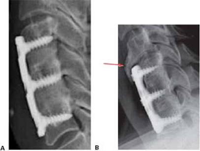
TECH FIG 7 • Proper plate sizing. A. The length of an optimally sized plate is such that the screw holes at the top and bottom of the construct are immediately adjacent to their respective endplates. In this example, even though this was done, the plate is still closer to the cephalad adjacent disc space than ideal because the vertebral bodies in this patient are relatively short. Nevertheless, adjacent-level disc degeneration did not occur in this patient at 2-year follow-up. Bicortical screw purchase is not routinely needed, but estimates of screw length can be obtained by measuring MRI or CT scans preoperatively. Screws should be angled away from the disc space to provide greater length and divergent fixation, which may better resist pullout. B. This patient also has short vertebrae. However, this plate was placed too close to the adjacent disc, resulting in adjacent-level ossification disease (arrow). The cephalad screws are not immediately adjacent to the endplate but rather inserted at roughly the midpoint of the vertebral body. Similarly, the caudal screws begin in the midportion of the vertebral body. The plate is too long distally and comes close to the subjacent disc as well. As demonstrated by these examples, proper plate sizing is especially important in patients with shorter vertebrae, where the adjacent discs are closer together.

TECH FIG 8 • Dynamic plates generally fall into three categories: those with variable screws that fit into round holes that allow for toggling of the screws, those with slotted holes to allow for translation, and those in which the ends of the plate telescope or shorten. In contrast to the variable and slotted plates, with the telescoping plate design shown, the relationship between the ends of the plate and the adjacent disc spaces remains fixed as the plate dynamizes, because the plate shortens internally. Thus, progressive adjacent level disc impingement is less likely to occur with settling over time if it did not occur at the initial placement of the device.
If dynamic plates are used, the surgeon must perform the plating procedure to accommodate the anticipated settling without overlapping uninvolved adjacent discs.8
ANTERIOR CERVICAL DISCECTOMY AND FUSION WITHOUT INSTRUMENTATION
ACDFs were traditionally performed without plating.
Although plates may better preserve lordosis and achieve higher fusion rates in multilevel cases, avoiding plates may decrease operative time, decrease the amount of retraction on the soft tissue structures of the neck during surgery, and avoid plate-related complications such as screw backout or esophageal erosion.
However, if one chooses not to use a plate, autograft should be used rather than allograft, and rigid postoperative immobilization in a cervical orthosis is mandatory.
Up to three adjacent interbody cervical fusions can be safely performed without instrumentation.
The interspaces should be fused sequentially, meaning a decompression and fusion is completed at one interspace before the next is addressed.
Measuring the Space
After appropriate decompression, the depth and height of the interspace are measured without distraction (TECH FIG 9A,B).
A laminar spreader is then inserted to distract the interspace, and the height is again measured (TECH FIG 9C,D).
Without distraction, the height is generally 6 mm; with distraction, it can be to up to 12 mm.
This distraction is important in shaping the tricortical graft. The height of the graft should be greater than the resting height but less than the distracting height so that the inherent compression of the vertebral bodies will hold the graft firmly in place.
Inserting the Graft
After the appropriate size of cortical graft is obtained, it is inserted with the laminar spreader distracted (TECH FIG 10A,B).
The graft should have at least a 2-mm offset anteriorly, and the posterior edge of the graft should be 4 mm anterior to the dura and PLL.
After the distraction is released (Tech Fig 10C,D), the graft should be tested for stability by trying to dislodge it using a smooth right-angle probe.
Postoperatively, if the graft is stable, a simple soft collar should be used for 4 to 6 weeks.
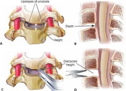
TECH FIG 9 • Measuring the interspace without (A,B) and with (C,D) distraction.

TECH FIG 10 • The cortical graft in place with (A,B) and without (C,D) distraction. Without distraction, the graft is compressed by the natural elasticity of the cervical spine. There is about 2 to 6 mm of free space between the posterior surface of the graft and the spinal cord.

POSTOPERATIVE CARE
The utility of bracing after plated ACDF is debatable.
We typically place the patient in a cervical collar for 6 weeks.
A deep drain is placed in the retropharyngeal space to prevent hematoma formation. It is typically removed the morning after surgery unless its output is greater than 30 cc in the last 8 hours.
The postoperative diet may be rapidly advanced as tolerated. Cold beverages and ice cream may help with dysphagia and reduce swelling in the immediate perioperative period.
OUTCOMES
Over 90% of patients experience excellent relief of radicular symptoms with ACDF.
Midline axial neck pain may improve if it is associated with radicular pain, but patients should be counseled that the primary goal of treatment is neural decompression and relief of radicular or myelopathic symptoms.
Similarly, unilateral neck pain can be a manifestation of radiculopathy and also generally improves.
However, isolated axial neck pain without radicular complaints does not predictably improve with surgery, and we recommend nonoperative treatment in such patients.
COMPLICATIONS
Complications potentially associated with ACDF include dysphagia, dysphonia, pseudarthrosis, implant failure, neurologic injury, esophageal injury, airway compromise from swelling or hematoma, and vertebral artery injury.1
Some degree of dysphagia is almost universal immediately after surgery. The majority of patients with dysphagia have only mild symptoms, with clinical improvement within 3 weeks. Long-term significant dysphagia is not common (about 4%).
The superior laryngeal nerve innervates the cricothyroid muscle, which adjusts the tension on the vocal folds and also provides supraglottic sensation. Superior laryngeal nerve palsies therefore may lead to difficulty with singing high notes as well as aspiration.
The recurrent laryngeal nerve innervates the muscles responsible for abducting the vocal folds. Recurrent laryngeal nerve palsy most commonly presents as hoarseness. Bilateral injuries can lead to airway obstruction and require tracheostomy.
Even with modern surgical techniques, nonunions still occur. However, many cervical nonunions are asymptomatic and do not require further treatment. Symptomatic nonunions can be addressed with revision ACDF or posterior laminoforaminotomy and fusion.
It is often argued that fusion accelerates adjacent-segment degeneration. Although biomechanical studies show increased disc pressures and mobility at discs adjacent to fusions, clinical series have not confirmed that adjacent-segment degeneration is truly accelerated by fusion versus simply being a manifestation of the patient’s propensity toward spondylosis. In fact, the available evidence suggests that about 3% of patients will have symptomatic adjacent-segment disease regardless of whether the index operation was ACDF, ACD without fusion, or posterior foraminotomy without fusion.7
REFERENCES
1. Bazaz R, Lee MJ, Yoo JU. Incidence of dysphagia after anterior cervical spine surgery: a prospective study. Spine 2002;27:2453–2458.
2. Brigham CD, Tsahakis PJ. Anterior cervical foraminotomy and fusion: surgical technique and results. Spine 1995;20:766–770.
3. Curylo LJ, Mason HC, Bohlman HH, et al. Tortuous course of the vertebral artery and anterior cervical decompression: a cadaveric and clinical case study. Spine 2000;25:2860–2864.
4. Ebraheim NA, Lu J, Haman SP, et al. Anatomic basis of the anterior surgery on the cervical spine: relationships between uncus-artery-root complex and vertebral artery injury. Surg Radiol Anat 1998;20:389–392.
5. Emery SE, Bolesta MJ, Banks MA, et al. Robinson anterior cervical fusion: comparison of the standard and modified techniques. Spine 1994;19:660–663.
6. Henderson CM, Hennessy RG, Shuey HM Jr, et al. Posterior-lateral foraminotomy as an exclusive operative technique for cervical radiculopathy: a review of 846 consecutively operated cases. Neurosurgery 1983;13:504–512.
7. Hilibrand AS, Carlson GD, Palumbo MA, et al. Radiculopathy and myelopathy at segments adjacent to the site of a previous anterior cervical arthrodesis. J Bone Joint Surg Am 1999;81A:519–528.
8. Park JB, Cho YS, Riew KD. Development of adjacent-level ossification in patients with an anterior cervical plate. J Bone Joint Surg Am 2005; 87A:558–563.
9. Radhakrishan K, Litchy WJ, O’Falon WM, et al. Epidemiology of cervical radiculopathy: a population-based study from Rochester, Minnesota, 1976 through 1990. Brain 1994;117:325–335.
10. Sampath P, Bendebba M, Davis JD, et al. Outcome in patients with cervical radiculopathy: prospective, multicenter study with independent clinical review. Spine 1999;24:591–597.
11. Smith GW, Robinson RA. The treatment of certain cervical spine disorders by anterior removal of the intervertebral disc and interbody fusion. J Bone Joint Surg Am 1958;40A:607–624.