
Mitchell F. Reiter and Saad B. Chaudhary
DEFINITION
 Several types of lumbar arthrodesis have been developed to address the various pathologic processes that occur.
Each of these fusion techniques offers certain advantages and disadvantages that provide the surgeon with a range of options for addressing each patient’s condition.
The standard lumbar arthrodesis techniques include:
 Anterior lumbar interbody fusion (ALIF)
Posterior spinal fusion (PSF), which includes two subtypes:
 Posterior interlaminar and facet fusion
Posterior lateral intertransverse fusion
Combined anterior and posterior fusion (AP fusion or 360-degree fusion)
Posterior lumbar interbody fusion (PLIF) and its variant the transforaminal lumbar interbody fusion (TLIF)
The PLIF procedure uses a posterior approach to the spine that involves radical discectomy and endplate preparation combined with an interbody fusion using a structural graft or cage with or without supplemental posterior instrumentation.
The TLIF procedure is similar to PLIF with the modification that the interbody region is accessed unilaterally via a more lateral approach in conjunction with pedicle screw instrumentation.
PLIF and TLIF are versatile techniques that offer several advantages over the other fusion methods.2
They allow for pathology in all three columns of the spine to be addressed and for a circumferential fusion to be achieved through a single posterior approach.
They directly address the disc as a potential pain generator in patients with discogenic pain syndromes.
They have demonstrated a high rate of fusion that approximates the arthrodesis rate achieved with a more extensive combined anterior and posterior fusion procedure.
They allow for direct decompression of the spinal canal if necessary.
They permit some correction of spinal deformities, including asymmetric disc space collapse, spondylolisthesis, and mild kyphosis.
PLIF and TLIF procedures also avoid some of the drawbacks inherent to anterior lumbar interbody fusion procedures, such as:
There is a reduced risk of the complications associated with an anterior approach, including vascular injury, higher rates of thromboembolic disease, and retrograde ejaculation in males.
They preserve a virgin anterior approach should revision surgery become necessary or should an adjacent segment arthroplasty become an option in the future.
PLIF and TLIF have the disadvantage, however, of potential nerve root injury from preparation and instrumentation of the disc space through a posterior approach.
ANATOMY
The standard posterior approach to the lumbar spine is used for posterior interbody fusion techniques.
Applied surgical anatomy considerations for TLIF and PLIF are nearly identical, with both techniques using a midline incision and standard posterior exposure.
Both PLIF and TLIF techniques require that the interbody region be accessed via posterior annulotomy.
The major difference is that the PLIF procedure uses a bilateral and more-medial approach to access the interbody region, whereas the TLIF technique involves a unilateral approach with complete removal of one facet joint to allow more lateral access to the disc space (FIG 1).
As a result, the exiting root is in greater danger when performing a TLIF, whereas the traversing root is in greater danger with a PLIF.
Gaining access to the posterior annulus and interbody region during TLIF and PLIF procedures is a critical step that requires an understanding of the local neurologic anatomy and the triangular working window to the annulus. The triangular working window consists of the following:
The traversing nerve root and thecal sac form the medial border of the triangle.
The exiting nerve root from the proximal vertebral level forms the lateral border (eg, L4 for an L4–5 TLIF or PLIF).
The superior aspect of the pedicle of the distal vertebra forms the base of the triangle.
A confluence of epidural veins traveling longitudinally and transversely drapes the floor of the spinal canal and neuroforamen.
With careful exposure, a triangular working window measuring up to 1.5 cm wide and of slightly greater height can be created.
A noncollapsed disc space of an adult lumbar spine averages between 12 and 14 mm in height, with an anteroposterior diameter of about 35 mm.4
PATHOGENESIS
The PLIF and TLIF procedures allow for fusion of the anterior column of the spine in the interbody region, which offers several biologic and biomechanical advantages over posterior spinal fusions:
The anterior column of the spine is known to support 80% of the body’s compressive load; consequently, intervertebral structural grafts are subjected to compressive loading, which facilitates arthrodesis.
Since interbody structural grafts are load-sharing, they significantly reduce the cantilever bending forces applied to posterior spinal implants, thus protecting them from failure.
The interbody space has been shown to provide an optimal milieu for promoting arthrodesis for several reasons:
A large surface area of highly vascular cancellous bone is available.

FIG 1 • A. PLIF technique, demonstrating the bilateral approach to the interbody region with complete facetectomies. Medial retraction of the neurologic elements is necessary to facilitate access to the disc space. B. TLIF technique, demonstrating the more lateral approach to the disc space with unilateral facetectomy. With the TLIF technique, medial retraction of the neurologic elements is frequently not needed. (A, Courtesy of Medtronic; B, Courtesy of Synthes Spine.)
The disc space represents a relatively shorter gap to span when compared to intertransverse fusion.
The outer annulus serves as a barrier that reduces fibrous tissue ingrowth into the fusion mass during healing of an interbody arthrodesis.
INDICATIONS
Discogenic pain syndromes due to internal disc disruption or degeneration as well as postdiscectomy chronic low back pain are well suited to PLIF or TLIF for several reasons:9,12
These procedures directly address the disc as the pain generator and have been shown to have superior clinical outcomes in treating discogenic pain compared to isolated posterior spinal fusions, which do not remove and fuse the painful disc.
They allow for restoration of interbody height and some correction of local kyphosis without putting undue stress on the posterior implants.
They permit decompression of the exiting and traversing nerve roots indirectly by restoring foraminal height and directly via open laminectomy and foraminotomy. Because of this, PLIF and TLIF are ideally suited to patients with discogenic pain syndromes occurring in conjunction with radicular symptoms caused by herniated disc pathology or stenosis (FIG 2).
Low-grade isthmic spondylolisthesis can also be treated successfully with PLIF and TLIF procedures as an alternative to performing a combined anterior and posterior fusion.10
PLIF and TLIF allow for direct decompression of the spinal canal and exiting nerve roots as well as indirect foraminal decompression through restoration of disc space height.
Addition of the interbody fusion raises the arthrodesis rate over stand-alone posterior fusion.
When clinically indicated and with proper instrumentation, PLIF and TLIF allow for reduction of the spondylolisthesis and slip angle, with some restoration of lordosis. In experienced hands and in conjunction with a wide decompression and intraoperative neurologic monitoring, some higher-grade spondylolistheses can be successfully reduced and stabilized with the PLIF and TLIF procedures.
PLIF and TLIF procedures can be a useful adjunct to adult deformity surgeries such as degenerative scoliosis and spondylolisthesis and offer several advantages:
They can be used to provide anterior column support at the caudal end of fusion constructs and the lumbosacral junction without requiring an additional anterior approach to the spine.
They improve the arthrodesis rate, which can be helpful when an interlaminar fusion is not possible because a midline decompression was necessary to address spinal stenosis.

FIG 2 • A. T2-weighted sagittal MRI image demonstrating L5–S1 disc degeneration with a recurrent disc herniation in this patient who had undergone a previous L5–S1 discectomy. B. T2-weighted axial image of the same patient. Note the dorsal displacement of the traversing left S1 nerve root (thin arrow) by the disc and the previous left-sided laminotomy defect (thick arrow).
They allow for some additional deformity correction by releasing asymmetrically collapsed disc spaces and providing interbody structural support.
Several recent presentations (not yet published) have found that routine cases of degenerative spondylolisthesis may not benefit from the addition of an interbody arthrodesis and may be best managed with standard posterior laminectomy and fusion procedures.
PLIF and TLIF can also help raise the fusion rate in arthrodesis procedures in which clinical conditions pose a challenge to spinal fusion, such as:
Patients unwilling or unable to quit smoking
Patients with diabetes mellitus or on systemic corticosteroids
Patients on chemotherapy or with an irradiated fusion bed
Revision spinal fusion procedures in which the posterolateral fusion bed is fibrotic and hypovascular
Any other situations in which the clinician feels that the addition of an interbody arthrodesis is justified because conditions exist that may impede the formation of a posterior arthrodesis
CONTRAINDICATIONS
PLIF should not usually be attempted at the level of the conus medullaris (typically L1–2) or above, and great caution must be taken using the TLIF procedure at the level of the cord or conus.
Severe osteoporosis is a relative contraindication to these procedures as disc space preparation can result in major endplate violations with subsequent implant subsidence.
Anomalous neural anatomy such as a conjoined nerve root can make the performance of a PLIF or TLIF procedure impossible.
Even in some cases of “normal” nerve root anatomy, local variations in take-off angles of the exiting and traversing roots can place the roots at risk during interbody approaches. Caution should be exercised in such cases and interbody fusion abandoned if not felt to be safe.
Severe focal kyphosis is poorly addressed with a PLIF or TLIF procedure and is usually better treated with an anterior procedure that allows for release of the anterior longitudinal ligament and annulus fibrosus.
Irreducible higher-grade spondylolistheses are not well treated with the PLIF and TLIF procedures as the surface area of the opposing vertebral endplates is minimized.
NONOPERATIVE MANAGEMENT
Before considering PLIF and TLIF surgeries, standard nonoperative management options for the pathologic conditions being addressed should typically be exhausted.
Nonsurgical treatment usually involves a combination of analgesic medications, physical therapy, and activity and lifestyle modification. When applicable, interventional pain management techniques such as trigger point injections, facet blocks, or epidural steroid injections should be considered.
Surgical intervention is usually reserved for patients who remain symptomatic despite several months of nonoperative treatment and whose symptoms are severe enough to justify the risks associated with operative care.
SURGICAL MANAGEMENT
As mentioned earlier, PLIF and TLIF procedures are capable of addressing a wide variety of pathologic conditions and in specific situations offer several compelling advantages.
Given their versatility, the well-trained spinal surgeon needs to be aware of the indications for these procedures and must be capable of executing them properly.
While the usefulness of the PLIF and TLIF procedures is clear, one must remain mindful that these procedures are technically demanding and should be undertaken only after careful training and preoperative planning and with meticulous surgical technique.
Preoperative Planning
Preoperative imaging studies should be reviewed to determine the appropriate size and trajectories necessary for pedicle screw insertion as well as the anteroposterior diameter of the disc space.
Disc space height as well as adjacent disc height and overall lumbar alignment should be measured to help determine optimal interbody implant size.
An assessment should be made as to whether direct or indirect neurologic decompression will be necessary.
When using the TLIF technique, the interbody approach should be performed on the patient’s symptomatic side if he or she has radicular complaints or from the side of maximal neurologic compression if the lower extremity symptoms are of equal severity.
Although sometimes difficult to assess, the patient’s MRI needs to be studied carefully to identify anomalous neural anatomy such as a conjoined nerve root.
If a conjoined nerve root is suspected, the TLIF should be performed from the opposite side and the patient should be counseled preoperatively that the interbody portion of the procedure may not be possible because the contralateral side may demonstrate intraoperative nerve root anomalies as well.
For the PLIF procedure, the presence of a conjoined nerve root usually necessitates a unilateral PLIF. If identified preoperatively, conversion to a TLIF should be strongly considered.
Deformity at the level of the planned fusion needs to be assessed so that intraoperative measures can be taken to provide for correction.
Positioning
The patient should be positioned prone on an operating room table that allows for fluoroscopic imaging, such as a Jackson spine table (FIG 3).
The abdomen should be free to decompress the vena cava. This maneuver has been found to reduce epidural venous engorgement and bleeding.
A Foley catheter and lower extremity sequential compression devices should be used routinely.

FIG 3 • Prone positioning with the abdomen free of compression, lower extremity compression devices in place, knees flexed, and all bony prominences padded. All tubes and wires are secured so that the area under the patient is free of obstruction, which facilitates later use of the fluoroscopy unit.
Pillows should be used to keep the knees slightly flexed to minimize tension on the lumbar nerve roots.
Intraoperative physiologic monitoring with somatosensory evoked potentials and “free run” electromyographic monitoring should be considered. Physiologic monitoring will also allow for pedicle screw stimulation testing to help detect any inadvertent pedicle wall breaches.
Approach
The standard posterior approach to the lumbar spine is used, including exposure out to the tips of the transverse processes so that an adequate intertransverse fusion can be performed.
Some surgeons choose to perform a more limited dissection and do not perform the posterolateral portion of the fusion, hoping that by preserving the blood supply and muscular attachments in the intertransverse region there will be reduced erector muscle dysfunction and fibrosis with improved outcomes.
True minimally invasive TLIF options have been developed. With these techniques, the procedure is modified so that it can be carried out through cannulas and with percutaneous instrumentations. These modifications will not be discussed in this chapter. The surgeon should be adept at open interbody fusions before considering minimally invasive approaches.
For the standard TLIF procedure, the spinous processes and interspinous ligaments can usually be left intact. Preserving these structures minimizes epidural scarring and provides a larger surface area for the posterior fusion.
If decompression of the contralateral side of the spinal canal is required, the TLIF procedure can be modified to include a central laminectomy.
Two exposure options exist for the PLIF procedure, each of which will be discussed in more detail later in the chapter:
Extensive resection including wide laminectomy with bilateral facetectomies
Limited resection using bilateral laminotomies and medial facetectomies
TECHNIQUES
TRANSFORAMINAL LUMBAR INTERBODY FUSION
Pedicle Screw Insertion
 After exposure, pedicle entry points are identified at the junction of the transverse process with the superior articular process of each vertebra.
A high-speed burr or awl is then used to access each pedicle, followed by use of a pedicle probe and tap to create a proper path for the screws.
Polyaxial pedicle screws are then placed bilaterally in the standard fashion.
Fluoroscopy or image guidance systems, electromyographic responses, or both can be used to aid in proper screw positioning.
If desired, the transverse processes can be decorticated using a high-speed burr or curette before screw insertion. This is recommended to facilitate the posterior arthrodesis as access to the transverse processes becomes somewhat limited once the pedicle screws are in place.
Disc Space Distraction
After screw placement, the next step is to provide posterior distraction to open the posterior portion of the disc space.
 Lumbar disc spaces are normally lordotic, which can make insertion of an appropriate-sized interbody cage through the narrow posterior portion of the disc space difficult.
With distraction, the disc space alignment can be neutralized, thereby facilitating access to the interbody region with minimal bony resection.
Several methods of achieving interbody distraction exist, and these can be combined as needed to achieve the desired alignment. The choice of distraction technique is largely based on surgeon preference, as all three methods have been found to be effective.
Distraction option 1: Use of rods and screws
Rods are loaded bilaterally into the pedicle screws, followed by provisional placement of the system’s locking nuts.
Distraction is then carried out using the rods on both sides and a standard distractor (TECH FIG 1A–C).
To allow for the distraction, the rods need to be slightly longer than will ultimately be necessary.
The polyaxial screw heads should be angled as laterally as possible to maximize the volume of space medial to the rods. This maneuver facilitates later access to the disc space without requiring rod removal.
Alternatively, several systems have pedicle screw distractor instruments that provide distraction off the screws without requiring rods to be inserted.
Distraction instruments obviate the need to use longer rods and allow for unimpeded access to the facet and disc space during interbody preparation and implant insertion.
 Lateral fluoroscopy should be used to judge the amount of distraction obtained at the posterior margin of the disc space.
Once adequate alignment is obtained, the system’s locking nuts are tightened to maintain the distraction.
Care should be taken not to excessively distract off the screws in osteoporotic patients, as this could lead to screw loosening.
Distraction option 2: Spinous process distraction
Distraction can also be achieved by using a lamina spreader placed between the spinous processes (TECH FIG 1D).
Distracting off the spinous process can reduce the risk of screw loosening that might occur with excessive distraction on the pedicle screws.
Distraction option 3: Interbody dilators
Another option available to facilitate interbody distraction is to use interbody dilators, which are placed into the disc space and rotated to restore disc space height (TECH FIG 1E).
This technique minimizes stress applied to the posterior implants and provides the most powerful method of vertebral body distraction.

TECH FIG 1 • Interbody distraction techniques. A. A distractor is placed over the rod between the pedicle screws. B. A two-level TLIF procedure. The upper-level disc space remains slightly lordotic before distraction using the rods and screws. C. Distraction has neutralized the upper disc space, which facilitates access for endplate preparation and graft insertion. D. Lamina spreader placed between the spinous processes. E. A dilator or shaver is placed into the disc space. (A, Courtesy of Depuy Spine; D, Courtesy of Synthes Spine; E, Courtesy of Aesculap.)
Use of interbody distractors is not possible until access to the disc space has been achieved, so this technique is not an option until the disc space has been accessed.
Complete Unilateral Facetectomy
The inferior articular process of the cephalad vertebra should be exposed and removed using an osteotome or rongeurs (TECH FIG 2A).
The superior articular process of the caudal vertebra is then dissected free of the ligamentum flavum with curettes and removed using Kerrison rongeurs. To maximize access to the disc space, the entire superior articular process down to the cephalad aspect of the pedicle should be removed so that the top of the pedicle can be easily seen and palpated (TECH FIG 2B).
The lateral aspect of the hemilamina and the caudal portion of the pars interarticularis are resected using Kerrison rongeurs to provide access to the neural foramen and posterolateral annulus.
The triangular working zone between the exiting and traversing nerve roots and the superior aspect of the pedicle should be identified (TECH FIG 2C).
The exiting nerve root is present just below the pedicle of the cephalad vertebra.
The exiting nerve can be identified visually or palpated but should not be deliberately manipulated as the sensitive dorsal root ganglion is in this region.
While it is critical to identify the location of the exiting nerve root, care should be taken not to unnecessarily dissect the nerve out of its sleeve of fatty tissue; in some cases the nerve will be located and palpated but never fully visualized.
The traversing nerve root and the lateral aspect of the thecal sac will be present in the medial portion of the triangle. Nerve root retractors can be used to mobilize the neurologic elements medially to provide additional access to the posterolateral annulus (TECH FIG 2D).
As in all lumbar spinal surgical procedures, if trouble is encountered locating a nerve root, the surgeon should find or palpate the associated pedicle and look along the medial and inferior pedicle wall.
With the neurologic elements accounted for, the posterolateral annulus can be accessed through the previously described triangular working zone by carefully coagulating and dividing the obstructing epidural veins using bipolar cautery (TECH FIG 2E).
Significant bleeding can be encountered at this stage, and the use of cottonoids in conjunction with hemostatic agents such as Gelfoam, Floseal, or Surgiflo can be helpful.
If the surgeon is not careful, the exiting or traversing nerve roots can be damaged while dealing with the bleeding arising from the epidural venous plexus. Working methodically while remaining constantly aware of the location of these neural structures is critical.
Disc Space Preparation
A nerve root retractor is used to mobilize the thecal sac and traversing nerve root medially to improve exposure of the posterolateral annulus. An advantage of the TLIF procedure is that minimal neural retraction is necessary to access the interbody region. Depending on the local nerve root anatomy, however, retraction of the traversing root may be necessary even with a TLIF.

TECH FIG 2 • A. Removal of inferior articular process. B. Removal of superior articular process. C. Exposure after unilateral facetectomy, with the triangular working zone outlined in gray. The exiting nerve root (red arrow) forms the lateral border and the traversing nerve root and thecal sac (blue arrow) form the medial border of the working zone. D. Intraoperative picture following facetectomy and discectomy. Pedicle screws at L4 and L5 are marked by the small and large white arrows, respectively. The exiting L4 nerve root (small black arrow) and the traversing L5 nerve root (large black arrow) are both being gently retracted, with the annular window into the interbody region (blue arrow) seen between them. E. Posterolateral annulus with overlying epidural veins. To avoid inadvertent injury while obtaining hemostasis, one must constantly be aware of the location of the neurologic elements when working in the epidural space. (C and E, Courtesy of Aesculap.)
A scalpel is then used to incise a rectangular region of the annulus lateral to the traversing nerve root to create a window into the disc space (TECH FIG 3A).
It is extremely important to have proper instruments available to facilitate the critical step of disc space preparation. These instruments are frequently provided by the vendor of the graft or implants to be used in the interbody region and should include (TECH FIG 3B):
Interbody paddle scrapers to dilate and prepare the endplates
Offset curettes to facilitate access to the contralateral side of the disc space
Rasps, ring curettes, and reverse curettes to assist in endplate preparation
Osteotomes or box chisels to improve access to the interbody region when the disc space is narrowed posteriorly
Long straight and upbiting pituitary rongeurs for débridement of the interbody region
After creation of the annular window, typically shavers or dilators of increasing size are serially introduced into the disc space and rotated (TECH FIG 3C,D).
Lateral fluoroscopy can be helpful in determining the proper depth of penetration into the disc space. The anterior and anterolateral annulus should be palpated by the instrument and never violated, or catastrophic vascular injury could occur.
Instruments used within the disc space are typically marked so that they are not overinserted to avoid potentially catastrophic violation of the anterior annulus. It is helpful to preoperatively estimate disc space length (posterior to anterior) on MRI or CT scan to have an idea of how far the instruments can be inserted.
After dilation and shaving, a combination of curettes and rongeurs is used to perform a thorough discectomy and endplate preparation down to bleeding bone (TECH FIG 3E,F).
Care should be taken not to violate the endplates in regions expected to load share with the interbody implant as this can make implant placement difficult and lead to settling of the structural graft.
Several TLIF techniques do call for perforation of the endplates to expose cancellous bleeding bone in 4622 non-load-sharing interbody regions, using osteotomes for the anterior portion of the disc space or curettes and awls for other areas.
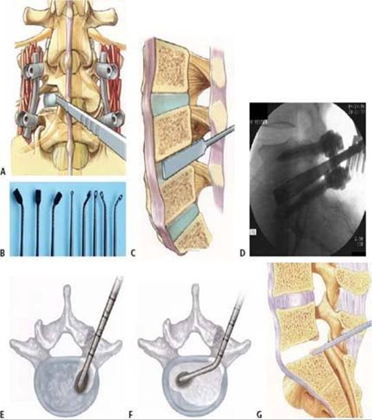
TECH FIG 3 • A. With the TLIF’s lateral approach, annular incision is frequently possible without neurologic retraction. B. Disc space preparation instruments (from left to right): left offset, straight, and right offset rasps, ring curette, reverse curette, straight, left, and right offset curettes. Other instruments not shown may include dilators, shavers, osteotomes, and straight and angled pituitary rongeurs. C.Schematic of a shaver introduced into a disc space. Rotation of the shaver should remove endplate cartilage to facilitate arthrodesis. D. Lateral fluoroscopic image of a shaver within the disc space at L5–S1. To avoid violation of the endplates, care must be taken when working in the interbody region to maintain a parallel trajectory to the disc space. Straight (E) and offset (F) curettes maximize the area of the disc space that can be accessed and facilitate proper endplate preparation. G.Access to concave disc spaces can be facilitated by removal of posterior endplate osteophytes. (A,C, Courtesy of Aesculap; B, Courtesy of Biomet Spine; E,F, Courtesy of Synthes Spine; G, Courtesy of Depuy Spine.)
Because of the concave nature of the endplates, it is sometimes necessary to use osteotomes or box chisels to remove a rim of bone from the posterior aspect of the vertebral bodies to improve access to the disc space and allow for placement of a properly sized graft (TECH FIG 3G). The surgeon should remember that aggressive removal of the posterior lip may lead to a greater risk of implant backout with root compression.
On completion of the discectomy and endplate preparation, exposed bony endplates should be visible on the cephalad and caudal vertebral bodies.
To minimize the risk of neurologic injury and postoperative dysesthetic pain, several recommendations should be followed during the disc space preparation and graft insertion:
Retraction on the neurologic elements should be minimized, and it should be released intermittently throughout the procedure.
The thecal sac should never be retracted across the midline of the spinal canal.
Particularly in revision cases, the neurologic elements should be carefully mobilized off the floor of the canal and disc space before retraction.
Implants should be selected that can be inserted without excessive neural retraction.
This can be an issue with use of threaded cylindrical cages because the height and width of the device must be equal; consequently, a cage of the appropriate height might be too wide to be safely inserted.
Graft Placement
A variety of interbody grafting techniques have been described for use in the TLIF procedure:
Placement of two vertical fibular allografts or vertical titanium mesh cages posteriorly in the disc space with cancellous graft packed anteriorly (TECH FIG 4A)
Use of an oblique threaded cylindrical cage or machined cortical allograft bone dowel (TECH FIG 4B)
Use of an obliquely placed rectangular PEEK cage or bullet-shaped cortical allograft
Placement of a curved titanium cage, PEEK cage, or machined cortical allograft anteriorly and as centrally as possible within the disc space, with cancellous graft placed behind the device (TECH FIG 4C)
While it has been shown that anterior cage placement is biomechanically superior to posterior cage placement, studies comparing the clinical efficacy of these various techniques do not exist.
When choosing an interbody graft and grafting technique, surgeons should consider several factors:
Ability to insert the device without requiring excessive neurologic retraction
Volume of cancellous graft that can be packed within and around the cage or allograft
The effect of the graft’s position and shape on the ability to restore lordosis with later compression of the posterior instrumentation6
The remainder of this section will describe the technique in which a single curved titanium or PEEK cage or allograft is placed anteriorly and centrally within the disc space.
After endplate preparation, graft trials should be used to determine the proper size for the interbody spacer (TECH FIG 4D). Fluoroscopic imaging should be used to confirm proper sizing of the trial.
The anterior and lateral aspects of the disc space should then be tightly packed with morselized graft material.
Several options are available for use as morselized graft material, including autogenous iliac crest bone graft, local bone graft from the removed facet and lamina, allograft corticocancellous bone, allograft demineralized bone matrix, ceramic bone graft extenders, and bone-inducing substances such as bone morphogenetic protein.
The choice of graft should depend on surgeon experience, host factors that may affect fusion, patient preference, cost, and availability.
Graft impactors should be used to maximize the amount of bone that can be placed into the interbody space. For the technique using a central and anteriorly placed cage, the anterior 25% of the disc space should be filled initially with tightly packed morselized graft material.
Before inserting the actual cage or graft, the trial should be reinserted to confirm that the morselized graft has not blocked the pathway for insertion of the structural graft.
The implant should then be inserted into the interbody space and placed anteriorly and as centrally as possible.
Implant position should be confirmed with AP and lateral fluoroscopy during insertion.
Straight and offset impactors can be used to facilitate proper cage positioning.
Additional morselized graft material should then be packed into the posterior aspect of the disc space behind the implant (TECH FIG 4E,F).

TECH FIG 4 • A–C. Several of the TLIF options available for graft type and position. A. Vertical cages or grafts placed posteriorly within the disc space with cancellous graft packed anteriorly. B. A single oblique threaded cage or graft. C. An anteriorly and centrally placed cage with cancellous graft placed posteriorly. D. Trial insertion to ensure that the appropriately sized device will fit and that cancellous graft packed into the disc space has not obstructed the pathway. E. Structural graft in place anteriorly with cancellous graft packed in the remaining portion of the disc space. F. Postoperative sagittally reconstructed CT scan demonstrating bone graft anteriorly, posteriorly, and within a titanium TLIF cage. (D–F, Courtesy of Synthes Spine.)
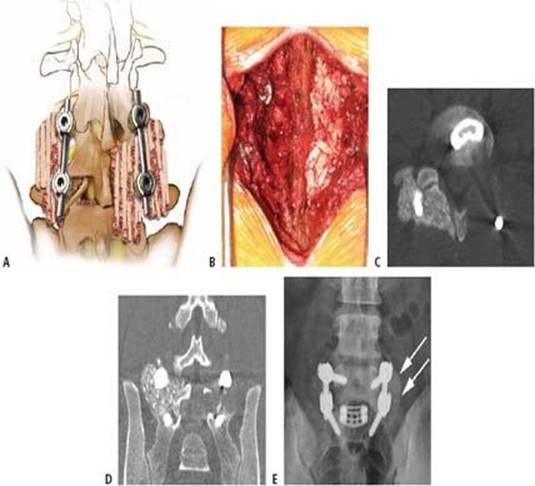
TECH FIG 5 • A. Schematic demonstrating posterolateral and interlaminar bone grafting. B. Intraoperative photograph with unilateral posterior morselized graft in place on right. Axial (C) and coronal (D) CT images demonstrating posterolateral and interlaminar graft in place. E. Postoperative radiograph demonstrating a solid unilateral arthrodesis (white arrow) in the posterolateral region. Assessment of fusion status in the posterolateral region is sometimes easier than assessing fusion within the interbody space.
Compression and Posterolateral Grafting
With the implant in place, distraction is released from the spinous processes or pedicle screws. Compression is then applied to the pedicle screw construct and the locking nuts are finally tightened.
Compression both loads the anterior implant and restores lordosis to the spine.
The contralateral spinous processes, lamina, facet joint, and transverse processes should then be decorticated (ideally the transverse processes were decorticated at the time of screw insertion).
Morselized graft can then be placed into the contralateral interlaminar, facet, and intertransverse regions (TECH FIG 5).
The interspinous ligament, if preserved, will serve to prevent graft migration into the exposed portion of the spinal canal and foramen.
Some surgeons may also wish to place graft on the ipsilateral side in the intertransverse region, but care must be taken to avoid allowing graft to enter the spinal canal or compress the exiting nerve root.
Final AP and lateral fluoroscopic images should be obtained.
Closure
Before closure, final hemostasis should be obtained and the neurologic elements inspected to ensure that no graft material has fallen into the spinal canal.
A Valsalva maneuver can also be performed to confirm the integrity of the dural sac.
A standard layered closure over a drain is then carried out.
POSTERIOR LUMBAR INTERBODY FUSION
Most of the technique for PLIF is similar to that described above for TLIF, except that a bilateral and more medial approach to the interbody space is used.
This section describes the PLIF procedure by highlighting the differences between the TLIF and PLIF techniques.
As noted in the exposure section, two PLIF exposure options are available (TECH FIG 6):
Extensive resection including wide laminectomy with bilateral complete facetectomies
Limited resection using bilateral laminotomies and medial facetectomies

TECH FIG 6 • Bony resections necessary for each of the two PLIF exposures. Wide laminectomy and complete facetectomies are demonstrated by the gray line. Laminotomy and partial facetectomies are shown by the red line.
The decision to use the wide laminectomy with total facetectomies is affected by several considerations:
It provides maximal exposure and minimizes the amount of neural retraction necessary to place the interbody grafts or implants. This is essentially a bilateral TLIF.
It should be strongly considered when fusing levels with a smaller interpedicular distance, such as in patients of short stature and in the upper lumbar spine.
It results in iatrogenic instability and therefore must be supplemented with pedicle screw instrumentation. Even with pedicle screws, a bilateral PLIF represents a more unstable situation. In patients with poor bone quality, the pedicle screws can loosen and lead to instability of the construct, with possible cage migration.
It eliminates the ability to fuse the facet joints posteriorly and reduces the host bone contact area available for the posterolateral fusion.
Limited resection using bilateral laminotomies and medial facetectomies:
Preserves the segment’s biomechanical stability by preserving the spinous processes, the interspinous ligaments, and most importantly the lateral half of the facet joints and associated pars interarticularis
Must be employed for cases in which posterior instrumentation is not being used
May be difficult in patients with a tall disc space as there may not be enough room for passage of the larger interbody graft required without more extensive resection of the facets
Should only be attempted by surgeons very familiar with the PLIF procedure as additional neural retraction is necessary, with a consequent higher risk of neurologic injury
After the exposure, pedicle screws are inserted and disc space distraction is applied as described for the TLIF procedure.
The PLIF procedure can be performed without pedicle screws if one uses the limited resection technique during exposure and care is taken not to destabilize the segment.
Laminotomy and Partial Facetectomy
If the partial resection technique is being used, a laminotomy is performed by using curettes to detach the ligamentum flavum from each of the adjacent lamina as well as the superior articular process of the caudal vertebra.
Kerrison rongeurs are then used to remove lateral portions of the adjacent lamina and the medial half of the superior and inferior articular processes.
This process should be repeated bilaterally and should result in working windows for approaching the disc space on each side of spinal canal.
When using the limited resection technique, care should be taken to preserve the spinous process, interspinous ligaments, lateral pars, and lateral half of the facet joints.
As in the TLIF procedure, the exiting and traversing nerve roots need to be identified and appropriate caution used to avoid traumatizing these sensitive neurologic structures during the procedure. To minimize root injury, one should remove enough lateral bone to be able to access the disc space without major retraction of the traversing root.
The wide laminectomy and bilateral facetectomy technique simply involves enlarging the above approach.
Resection of the spinous process and interspinous ligaments medially will improve the ability to retract the thecal sac toward the midline.
For a maximally sized working window, total facetectomies can be performed to allow for more lateral access to the disc space (see Fig 1A).
After exposure, the posterolateral annulus can be accessed through the previously described triangular zone cephalad to the pedicle of the inferior vertebra, medial to the exiting nerve root, and lateral to the traversing nerve root and thecal sac (see Tech Fig 2C).
Epidural veins are carefully coagulated and divided in the same way as described for the TLIF procedure.
Disc Space Preparation
Disc space preparation is performed in an identical fashion as described above for the TLIF procedure except that bilateral annular windows are created somewhat more medially than for a TLIF.
The thecal sac and traversing nerve root are mobilized medially, and a combination of shavers, curettes, and rongeurs is used to perform a thorough discectomy down to exposed endplate.
In noninstrumented PLIF procedures, achieving adequate interbody graft contact area is critical to reduce the risk of graft subsidence.
Closky et al1 demonstrated that in patients of average bone density and size, interbody graft contact area should exceed 6.2 cm2 or an area roughly 2.5 × 2.5 cm.
Instrumentation reduces the risk of subsidence but has not been shown to improve the clinical outcome when compared to properly performed noninstrumented PLIF procedures.
Graft Placement
The PLIF procedure requires the placement of structural interbody grafts inserted from each side of the spinal canal (TECH FIG 7).
As in the TLIF, many graft options exist, including structural autograft or allograft bone as well as threaded or rectangular titanium or PEEK implants.

TECH FIG 7 • Bilateral PLIF grafts surrounded by cancellous bone. (Courtesy of Medtronic.)
Dr. Lee4,8 has cautioned that most commercially available implants typically do not meet the surface area requirements for noninstrumented PLIF and should be used only when supplemented with pedicle screws.
Regions of the interbody space not filled with structural graft should be packed as tightly as possible with morselized graft material.
Fluoroscopy can be used to assess interbody implant position.
Compression, Posterolateral Grafting, and Closure
Compression (when pedicle screw instrumentation has been used), posterolateral grafting, and closure are all accomplished in a fashion similar to that described for the TLIF procedure.


POSTOPERATIVE CARE
The patient is typically mobilized out of bed the day after surgery.
Postoperative bracing is typically not required for the TLIF or instrumented PLIF procedures but can be used according to surgeon preference.
Most physicians prefer to use a thoracolumbosacral orthosis during the postoperative period for noninstrumented PLIF procedures.
Serial radiographs are used to assess for fusion.
OUTCOMES
Fusion rates for the PLIF and TLIF procedures are similar, with studies finding rates of obtaining a solid arthrodesis varying between 89% and 100%. Several recent larger studies have reported fusion rates above 95%.7,10,11
While clinical success rates vary between studies, most series report similar outcomes with PLIF and TLIF as for anterior interbody and combined anterior and posterior fusion procedures.
Most of the studies on PLIF and TLIF using visual analog scale (VAS) and Oswestry Disability Index (ODI) scores as outcome measures demonstrate an overall patient satisfaction rate of about 80% with the procedure.3,7,8,14
Longer-term studies indicate that the results of PLIF and TLIF procedures tend to be durable once a solid arthrodesis has been achieved.
COMPLICATIONS
Neurologic injury is an uncommon complication of PLIF and TLIF and has been reported to occur in between 0% and 4% of patients. Many of these injuries represent a neuropraxia due to excessive nerve root retraction and resolve spontaneously.13,15
Dural tears are a more common complication and have historically been reported to occur in 0.5% to 18% of PLIF and TLIF procedures.
The dural tear rate appears to be significantly lower with the TLIF procedure compared to the PLIF, likely related to the fact that less neural retraction is necessary when using the TLIF’s more lateral approach to the disc space.5
More recent studies demonstrate a trend toward much lower rates of dural tears in both PLIF and TLIF procedures, with a reported incidence in the range of 1% to 5%.
Implant migration or failure is a rare complication in the TLIF procedure but has been reported to occur in up to 2.4% of cases in which a noninstrumented PLIF is performed. Properly sizing the interbody implants and fully packing the disc space with graft material can help reduce the risk of this complication.
Other complications of posterior lumbar fusions that are not specific to the PLIF and TLIF procedure include wound infection, excessive bleeding, pedicle screw malposition, and epidural hematoma.
REFERENCES
1. Closkey RF, Parsons JR, Lee CK, et al. Mechanics of interbody spinal fusion: analysis of critical bone graft area. Spine 1993;18:1011–1015.
2. Enker P, Steffee AD. Interbody fusion and instrumentation. Clin Orthop Relat Res 1994;300:90–101.
3. Hackenberg L, Halm H, Bullmann V, et al. Transforaminal lumbar interbody fusion: a safe technique with satisfactory threeto five-year results. Eur Spine J 2005;14:551–558.
4. Herkowitz HN, Rothman RH, Simeone FA, eds. The Spine, ed 5. Philadelphia: Saunders Elsevier; 2006.
5. Humphreys SC, Hodges SD, Patwardhan AG, et al. Comparison of posterior and transforaminal approaches to lumbar interbody fusion. Spine 2001;26:567–571.
6. Kwon BK, Berta S, Daffner SD, et al. Radiographic analysis of transforaminal lumbar interbody fusion for the treatment of adult isthmic spondylolisthesis. J Spinal Disord Tech 2003;16:469–476.
7. Lauber S, Schulte TL, Liljenqvist U, et al. Clinical and radiologic 2to 4-year results of transforaminal lumbar interbody fusion in degenerative and isthmic spondylolisthesis grades 1 and 2. Spine 2006;31: 1693–1698.
8. Lee CK, Vessa P, Lee JK. Chronic disabling low back pain syndrome caused by internal disc derangements: the results of disc excision and posterior lumbar interbody fusion. Spine 1995;20:356–361.
9. Lin PM. Posterior lumbar interbody fusion (PLIF): past, present, and future. Clin Neurosurg 2000;47:470–482.
10. McAfee PC, DeVine JG, Chaput CD, et al. The indications for interbody fusion cages in the treatment of spondylolisthesis: analysis of 120 cases. Spine 2005;30:S60–S65.
11. Miura Y, Imagama S, et al. Is local bone viable as a source of bone graft in posterior lumbar interbody fusion? Spine 2003;28:2386–2389.
12. Moskowitz A. Transforaminal lumbar interbody fusion. Orthop Clin North Am 2002;33:359–366.
13. Okuda S, Miyauchi A, et al. Surgical complications of posterior lumbar interbody fusion with total facetectomy in 251 patients. J Neurosurg Spine 2006;4:304–309.
14. Potter BK, Freedman BA, Verwiebe EG, et al. Transforaminal lumbar interbody fusion: clinical and radiographic results and complications in 100 consecutive patients. J Spinal Disord Tech 2005;18:337–346.
15. Villavicencio AT, Burneikiene S, Bulsara KR, et al. Perioperative complications in transforaminal lumbar interbody fusion versus anterior-posterior reconstruction for lumbar disc degeneration and instability. J Spinal Disord Tech 2006;19:92–97.