
Kenneth A. Egol
DEFINITION
 The ankle is a modified hinge joint, which relies on a congruently reduced mortise to provide optimal function.
Maintenance of normal tibiotalar contact is essential if one is to maintain function.
Surgical treatment of displaced, unstable ankle fractures centers on anatomic restoration of the bony and ligamentous relationships that make up the ankle mortise.
This chapter will focus on the treatment of a specific pattern of injury to the ankle, specifically the bimalleolar fracture pattern.
ANATOMY
The anatomy of the distal tibia and ankle joint must be taken into account when considering ankle fractures. As the tibial shaft flares in the supramalleolar region, the dense cortical bone changes to metaphyseal cancellous bone (FIG 1A).
The shape of the tibial articular surface is concave, with distal extension of the anterior and posterior lips.
 This surface has been called the tibial plafond, which is French for ceiling.
The talar dome is wedge-shaped and sits within the mortise. It is wider anteriorly than posteriorly.
The medial end of the tibia is the medial malleolus.
The medial malleolus is composed of the anterior and posterior colliculi, separated by the intercollicular groove (FIG 1B).
The anterior colliculus is the narrower and most distal portion of the medial malleolus and serves as the origin of the superficial deltoid ligaments.
The intercollicular groove and the posterior colliculus, which is broader than the anterior colliculus, provide the origin of the deep deltoid ligaments.
The insertions of the deltoid ligaments (medial tubercle of the talus, navicular tuberosity, and sustentaculum tali) can also be considered part of the medial malleolar osteoligamentous complex.
The lateral malleolus is the distal end of the fibula. It extends about 1 cm distal and posterior compared to the medial malleolus.
The syndesmotic ligament complex unites the distal fibula with the distal tibia. The following ligaments make up the syndesmotic complex: the anteroinferior tibiofibular ligament, the posteroinferior tibiofibular ligament, the inferior transverse ligament, and the interosseous ligament (FIG 1C).
PATHOGENESIS
The majority of bimalleolar ankle fractures are secondary to rotation of the body about a supinated or pronated foot. They are best defined by the classification of Lague-Hansen (FIG 2).
The supination–external rotation pattern of ankle fracture is divided into four stages.
The stage 1 injury is tearing of the anterior inferior tibiofibular ligaments.
As the external rotation force continues laterally, a spiral fracture of the fibula occurs. On lateral radiograph, the fracture line will pass from the anteroinferior cortex to the posterosuperior cortex.
The third stage occurs when the posteroinferior tibiofibular ligaments avulse or fracture off the posterior malleolus.
The final stage results in a medial malleolar osteoligamentous complex injury with either a deep deltoid ligament tear or a fracture of the medial malleolus.
The pronation–external rotation variant also has four stages. Because of the pronated position of the foot at injury, however, the medial structures are injured in the early stages.
The fibula fracture pattern seen with this mechanism is usually suprasyndesmotic, and the fracture pattern is an anterosuperior-to-posteroinferior fracture line as seen on the lateral radiograph.
The supination–adduction pattern is heralded by a low transverse fibular fracture and a vertical shearing pattern medially. This pattern is also associated with tibial plafond impaction.
Finally, the pronation–abduction pattern is identified by the avulsion of the medial malleolus and a transverse or laterally comminuted fibular fracture above the syndesmosis secondary to a direct bending moment.
PATIENT HISTORY AND PHYSICAL FINDINGS
Most patients who present with ankle pain following trauma will describe a twisting type of injury. Less frequently they will report a direct blow to the ankle.
Proper medical history should include the patient's current comorbid medical conditions, such as peripheral vascular disease, diabetes, or peripheral neuropathy.
Physical examination should center on inspection, palpation, and neurovascular examination.
It is important to note any gross deformity, which may signify dislocation. If dislocation is present, the ankle should be reduced and splinted as soon as possible to prevent skin tenting and neurovascular compromise.
Inspection for any open wound about the ankle is critical as well. Open fractures imply a surgical urgency. Swelling, ecchymosis, and tenderness about the malleoli should be recorded.
For patients with a supination–external rotation pattern isolated fibula fracture who present with an intact mortise, the gravity stress examination can be revealing. More than 5 mm of medial clear space widening in association with a lateral malleolus fracture signifies an unstable pattern.
Pain at the ankle along the syndesmosis during a squeeze test implies injury to the syndesmosis.
The proximal fibula, knee, and tibia should also be examined. Palpation of pulses, detection of capillary refill, and a careful neurosensory examination must be documented prior to manipulation.
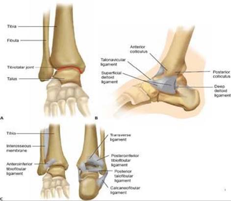
FIG 1 • A. Bony anatomy in the supramalleolar region of the distal tibia. B. Anatomy of the medial aspect of the ankle joint. C. Ligamentous anatomy about the ankle joint.
IMAGING AND OTHER DIAGNOSTIC STUDIES
Radiographic examination includes the ankle trauma series: anteroposterior (AP), lateral, and mortise view (FIG 3A–C).
In patients with isolated lateral malleolar fractures with clinical signs of medial injury, or if there is any question of ankle stability in a supination–external rotation fracture pattern, a manual external rotation stress radiograph should be obtained to assess for instability.
The tibia is held internally rotated 15 degrees with the ankle in dorsiflexion to produce a gentle external rotation moment at the ankle under fluoroscopy (FIG 3D).
More than 5 mm of medial clear space widening in association with a lateral malleolus fracture signifies an unstable pattern (FIG 3E).
If clinically warranted, full-length tibia–fibula radiographs should be obtained.
Restoration of medial ankle stability depends on the size and location of the medial malleolar fragment.
The size of the medial fragment is key to stability.
Anterior collicular fractures will have only the superficial deltoid attached. In about 25% of supination–external rotation type 4 injuries there will be an associated deep deltoid rupture. Thus, fixation of this fragment will not enhance stability.
The lateral radiograph is the key. If the fragment is greater than 2.8 cm wide, the deep deltoid will be attached and stability is restored. If the fragment is less than 1.7 cm wide, then stability is not restored with fixation. For fractures in between, an intraoperative external rotation stress examination should be performed following malleolar fixation.
CT scanning may be helpful in assessing posterior malleolar fragment size in rotational ankle fractures.
MRI may have some utility if there is an isolated lateral malleolus fracture with signs of medial injury and an equivocal stress examination.
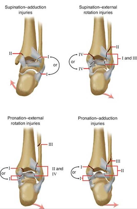
FIG 2 • The Lague-Hansen classification of ankle fractures.
DIFFERENTIAL DIAGNOSIS
Ankle sprain
Lateral malleolus fracture
Bimalleolar ankle fracture
Trimalleolar ankle fracture
Lateral process talus fracture
Anterior process calcaneus fracture
Subtalar dislocation
NONOPERATIVE MANAGEMENT
Ankle fractures in which the ankle mortise remains stable can be treated nonoperatively.
Isolated lateral malleolus fractures without evidence of medial-sided injury are considered supination external rotation type 2 injuries and can be treated with functional bracing and weight bearing as tolerated.
Unstable patterns such as supination–external rotation type 4, either ligamentous or a true bimalleolar or trimalleolar ankle fracture, can also be treated nonoperatively in patients who are poor surgical candidates (eg, insulindependent diabetics), who have severe soft tissue problems, or who do not wish to undergo surgical stabilization.
If nonoperative treatment is chosen, it is crucial to ensure anatomic mortise reduction throughout treatment until healing.
Unstable injuries should be treated in a well-molded shortleg cast and checked on a weekly basis to ensure continued mortise reduction.
SURGICAL MANAGEMENT
Any fracture of the ankle in which there is residual talar tilt or talar subluxation such that the ankle mortise is not anatomically reduced is an indication for surgical stabilization.
Preoperative Planning
Surgical anatomy should be reviewed prior to entering the operating room, including the bony and ligamentous structures.
The neurovascular anatomy about the ankle should be reviewed, including the course of the saphenous vein medially and the superficial peroneal nerve laterally.
Equipment to be used includes a small fragment plate and screw set, large pelvic reduction clamps, small-diameter Kirschner wires, and 3.5- to 4.0-mm cannulated screw sets. If the nature of the fracture is still in question, radiographic stress examination may be performed under anesthesia.
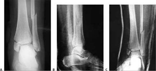

FIG 3 • Radiographic evaluation with an ankle trauma series: AP (A), lateral (B), and mortise (C) views. Clinical (D) and radiographic (E) demonstration of a physician-assisted external rotation stress examination of the ankle.
Positioning
The patient is positioned supine with a small bump under the ipsilateral hip to ease access to the fibula.
A pneumatic tourniquet can be applied to the affected thigh if desired for use during the surgical procedure. The affected limb is prepared and draped free.
The bump may be removed after lateral fixation for easier access to the medial side.
In rare cases, if a posterior approach is chosen, the patient may be placed in the prone position to allow access to the posterior tibia via the posterolateral approach.
Approach
The fibula is approached via a direct lateral incision.
The medial malleolus is approached via a gently curved anteromedial incision.
Direct access to the posterior malleolus can be obtained through a posterolateral approach to the fibula.
TECHNIQUES
DIRECT LATERAL APPROACH TO THE FIBULA
Exposure
 The incision is kept just off the posterior border of the fibula but may be adjusted slightly based on soft tissue considerations (TECH FIG 1A).
Deeper tissues are incised in line with the skin incision (TECH FIG 1B).
Care must be taken proximally in the wound to avoid injury to the superficial peroneal nerve, which crosses the field about 7 cm proximal to the distal tip of the fibula (TECH FIG 1C).

TECH FIG 1 • Surgical approach to the fibula, direct lateral. A. Skin incision marked out just along the posterior border of the fibula, centered about the level of the fracture. B. Incision through the peroneal (lateral compartment) fascia, exposing the fracture site. C. Identification of the superficial peroneal nerve as it crosses proximally in the wound.
Next, the peroneal fascia is divided and the peroneal tendons and musculature are retracted posteriorly.
 With gentle elevation of the periosteum about the fracture site, the fibula should be exposed.
Care should be taken to avoid excessive stripping of fracture fragments as well as iatrogenic disruption of the syndesmotic ligaments as they insert anteriorly on the fibula.
Lateral Plating
Following exposure of the fracture, the first step involves cleaning the fracture site (TECH FIG 2A), followed by fracture reduction.
Usually reduction is afforded by a small “lion jaw” clamp or pointed reduction forceps.
If reduction is difficult, manual traction with pronation and external rotation will afford fracture alignment in supination–external rotation patterns.
Care should be taken to avoid placing clamps over fracture spikes to prevent inadvertent comminution (TECH FIG 2B).
If the clamps make it difficult to place a lag screw, provisional Kirschner wires may be placed across the fracture and the clamps removed (TECH FIG 2C).
At this point, if a lateral plate is chosen, the lag screw is placed in the anterior-to-posterior direction, perpendicular to the fracture.
If a posterior plate (antiglide) is chosen, the lag screw is placed through the plate in a posterior-to-anterior direction.
In either case, the near cortex is overdrilled with a 3.5-mm drill bit, followed by drilling of the far cortex with a 2.5-mm drill bit (TECH FIG 2D).
The length of the screw is measured and a self-tapping 3.5-mm screw is placed across the fracture in the screw track.
Next a one-third tubular plate is placed directly lateral on the fibula (neutralization).
The proximal screw holes are filled with bicortical 3.5-mm screws after drilling with the 2.5-mm drill bit (TECH FIG 2E).
Distally, unicortical cancellous screws are placed, with care not to penetrate the distal tibia–fibula joint (TECH FIG 2F).
The wound is closed (TECH FIG 2G).
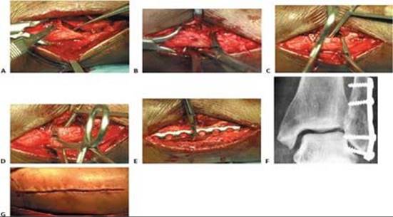
TECH FIG 2 • A. Cleaning the fracture site with a small curette. B An example of clamp placement across the fibular fracture site. Care is taken not to comminute the fracture spike. C. Lag screw placement, overdrilled with a 3.5-mm bit proximally. D. This is followed by drilling of the far cortex with a 2.5-mm drill. E. A neutralization plate is applied to the lateral surface of the fibula. F. Example of distal screw penetration to be avoided. G.Wound closure.
ANTEROMEDIAL APPROACH TO THE MEDIAL MALLEOLUS
Exposure
The medial malleolus is approached via a gently curved anteromedial incision (TECH FIG 3A).
An incision is made parallel to the saphenous vein that is either concave anterior or concave posterior to allow visualization of the anteromedial joint.

TECH FIG 3 • A. For a medial-side injury, the skin incision is curved about the medial malleolus. B. Fracture site is exposed and cleaned of hematoma and the talar dome is inspected for signs of chondral injury.
After dissection of the skin, the subcutaneous tissues should be carefully dissected to prevent injury to the saphenous vein and nerve.
With the dissection carried down sharply to the bone, the periosteum is elevated for 1 mm proximally and distally.
The fracture should be booked open to allow visual inspection of the talar dome for chondral injury.
The joint and medial gutter should be irrigated through the fracture for any loose hematoma or debris that may impede reduction (TECH FIG 3B).
Operative Stabilization
Following exposure, the medial malleolar fragment (usually one large piece) can be reduced with the aid of a dental tool or small pointed reduction clamp (TECH FIG 4A).
*************************
The fragment can be provisionally stabilized with smalldiameter Kirschner wires placed in parallel (TECH FIG 4B).
After radiographic documentation of the reduction and wire placement, cannulated screws of appropriate length may be placed over the wires after drilling of the out cortices with a cannulated drill. Alternatively, noncannulated screws may be used independent of the provisional stabilization.
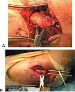
TECH FIG 4 • A. Reduction is achieved with a pointed reduction clamp. B. Guidewires for cannulated screws are placed across the fracture.
Usually, a 4.0-mm partially threaded cancellous screw can be placed. If the fragment is small, however, 3.5- or 3.0-mm cannulated screws are now available.
More recent studies have advocated for the use of two bicortical 2.7-mm screws placed in lag mode.
Two screws are recommended for rotational control. If the fragment is too small, however, one screw may suffice owing to the inherent stability of the undulating fracture line.
Countersinking the screw heads medially may help to alleviate painful prominent hardware.
Comminuted fractures that are not amenable to screw fixation may benefit from a small buttress plate or a “suture tension band” technique using the deltoid ligament for fixation.
The suture or wire tension band is anchored about a more proximal screw placed parallel to the articular surface.
POSTEROLATERAL APPROACH TO THE TIBIA
Direct access to the posterior malleolus fracture (TECH FIG 5A) can be obtained through the posterolateral approach to the fibula (TECH FIG 5B).
The interval between the Achilles and the peroneal muscle is developed (TECH FIG 5C).
The flexor hallucis longus is taken off the fibula down to the interosseous membrane, and then the rest of the deep posterior compartment is taken off the posteriortibia (TECH FIG 5D).
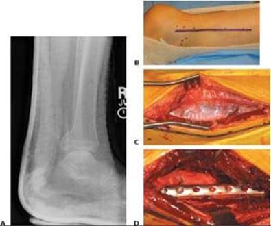
TECH FIG 5 • Direct posterior plating is well suited for fractures involving large portions of the posterior malleolus. A. Postreduction lateral radiograph showing a posterior malleolus fracture involving more than one third of the articular surface. B. Patient in prone position, incision between Achilles and posterior fibula border. C. Access is via the interval between the flexor hallucis longus and the peroneal muscle belly. D. Posterior malleolar fragment following fibular plating.
POSTERIOR MALLEOLUS FIXATION
If an adequate reduction can be achieved via closed, indirect reduction, the fracture can be stabilized with cannulated lag screws placed in the anterior-to-posterior direction.
If an open approach is used for reduction, screws placed posterior to anterior may be placed across the fracture site.
If the fracture fragment is of sufficient size, an antiglide plate (one-third tubular) may be placed with undercontouring of the plate to provide a satisfactory buttress effect (TECH FIG 6).
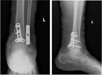
TECH FIG 6 • Postoperative AP and lateral radiographs demonstrating posterior plating of the tibia to buttress the posterior malleolar fracture fragment.
POSTERIOR PLATING OF THE FIBULA
In this case, the surgical approach is similar to the lateral plating technique.
When application of a posterior or antiglide plate is chosen, placement of a lag screw is optional.
My preferred method is to apply the plate along the flat posterior surface of the bone, using it as a reduction aid with a bone reduction clamp (TECH FIG 7A).
I prefer to place a posterior-to-anterior–directed lag screw through the plate.
Because of the biomechanical properties of this plate construct, this lag screw is optional.
Next, at least two or three bicortical screws are placed in the plate. A bicortical screw placed posterior to anterior in the distal screw is optional.
If a posterior plate is applied, the proximal screws are placed bicortically from posterior to anterior, both proximal and distal to the fracture. This is an advantage in osteoporotic bone (TECH FIG 7B).
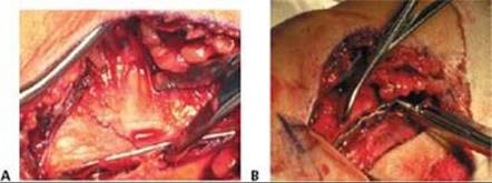
TECH FIG 7 • An alternative for plate placement is along the posterior border of the fibula. A. In this construct the implant is an antiglide plate. B. The lag screw can be placed from posterior to anterior with bicortical purchase achieved in each screw.
SYNDESMOSIS FIXATION
After stabilization of the medial and lateral sides of the ankle, syndesmotic integrity should be assessed.
The Cotton test involves providing a lateral force on the fibula with a bone hook or bone clamp (TECH FIG 8A).
Lateral displacement that allows more than a few millimeters of tibiofibular widening is considered pathologic and an indication for syndesmotic fixation.
The lateral radiograph should be scrutinized to assess the relationship of the fibula to the articular surface of the ankle joint. In general, on a true lateral view of the ankle, the tip of the fibula should be anterior to the posterior border of the diaphyseal tibia, but comparisons to the contralateral ankle can be assessed.
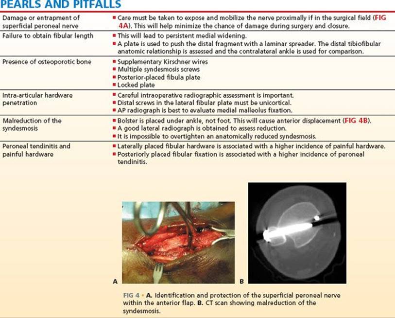
With a bolster behind the ankle, a large tentaculum clamp is placed across the tibiofibular joint, with one tine on the distal tibia and the other on the fibula (TECH FIG 8B).
Reduction is confirmed on the AP, mortise, and lateral radiographic views.
While dorsiflexion of the talus has been recommended in the past to prevent overtightening of the syndesmosis, more recent studies have shown that it is virtually impossible to overtighten an anatomically reduced mortise.
Fixation choices range from one or two screws, with three or four cortices drilled and 3.5-mm or 4.5-mm screw diameters used. Although the size and number of screws remain controversial, some parameters are agreed on.
The screw should be placed 1.5 to 2 cm proximal and parallel to the joint.
The screw should not be placed in lag mode.
If a lateral plate is used, the screw is placed through one of the distal holes.
If a posterior plate is used, the syndesmosis screw will likely be placed outside the plate on the lateral cortex.
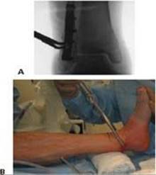
TECH FIG 8 • A. The Cotton test is performed following fibular fixation by pulling laterally with a hook or clamp to assess the integrity of the syndesmosis. B. Reduction and stabilization of the syndesmosis is achieved with a clamp placed across the distal tibiofibular joint and a bump placed under the leg.
POSTOPERATIVE CARE
All ankles should be splinted in the neutral position and elevated for at least 24 hours postoperatively.
We remove the splint at 10 to 14 days and remove the sutures.
Patients are then placed into a removable functional brace that allows them to begin early active-assisted and passive range of ankle motion.
Patients are also allowed to begin isometric strengthening exercises.
All patients are kept non-weight bearing for at least 6 weeks.
At 6 weeks patients are progressed to weight bearing as tolerated based on radiographic criteria.
Weight bearing can be delayed for slow healing and presence of a syndesmotic screw. In general we do not alter the weight-bearing status because of syndesmotic injury or routinely remove the syndesmosis screw, but we advise patients of the possibility of screw breakage following weight bearing.
Patients are restricted from operating an automobile for 9 weeks following right-sided ankle fracture.
OUTCOMES
One year after ankle fracture surgery, patients generally do well, with most experiencing little or mild pain and few restrictions in functional activities. They have significant improvement in function compared with 6 months after surgery.
Younger age, male sex, absence of diabetes, and a lower American Society of Anesthesia class are predictive of functional recovery at 1 year following ankle fracture surgery.
It is important to counsel patients and their families on the expected outcome after injury with regard to functional recovery.
Looking specifically at elderly patients (older than 60 years), functional outcomes steadily improved over 1 year of follow-up, albeit at a slower rate than in the younger patients.
Our results suggest that operative fixation of unstable ankle fractures in the elderly can provide a reasonable functional result at the 1-year follow-up.
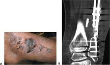
FIG 5 • A. Skin necrosis and slough following surgical intervention. B. CT scan demonstrating fibular nonunion at 6 months following open reduction and internal fixation of a pronation–abduction injury.
COMPLICATIONS
Minor complications include epidermolysis (FIG 5A), superficial infection, and peroneal tendinitis with painful hardware.
Major problems include nonunion (FIG 5B), hardware failure, deep infection, and compartment syndrome.
REFERENCES
1. Egol KA, Amirtharajah M, et al. Ankle stress test for predicting the need for surgical fixation of isolated fibular fractures. J Bone Joint Surg Am 2004;86A:2393–2398.
2. Egol KA, Dolan R, et al. Functional outcome of surgery for fractures of the ankle: a prospective, randomised comparison of management in a cast or a functional brace. J Bone Joint Surg Br 2000;82B:246–249.
3. Egol KA, Sheikhazadeh A, et al. Lower-extremity function for driving an automobile after operative treatment of ankle fracture. J Bone Joint Surg Am 2003;85A:1185–1189.
4. Egol KA, Tejwani NC, et al. Predictors of short-term functional outcome following ankle fracture surgery. J Bone Joint Surg Am 2006; 88A:974–979.
5. Lauge-Hansen N. Fractures of the ankle. II. Combined experimentalsurgical and experimental-roentgenologic investigations. Arch Surg 1950;60:957–985.
6. McConnell T, Creevy W, et al. Stress examination of supination external rotation-type fibular fractures. J Bone Joint Surg Am 2004; 86A:2171–2178.
7. Michelson JD. Fractures about the ankle. J Bone Joint Surg Am 1995;77A:142–152.
8. Pankovich AM, Shivaram MS. Anatomical basis of variability in injuries of the medial malleolus and the deltoid ligament. II. Clinical studies. Acta Orthop Scand 1979;50:225–236.
9. Park SS, Kubiak EN, et al. Stress radiographs after ankle fracture: the effect of ankle position and deltoid ligament status on medial clear space measurements. J Orthop Trauma 2006;20:11–18.
10. Pettrone FA, Gail M, et al. Quantitative criteria for prediction of the results after displaced fracture of the ankle. J Bone Joint Surg Am 1983;65A:667–677.
11. Phillips WA, Schwartz HS, et al. A prospective, randomized study of the management of severe ankle fractures. J Bone Joint Surg Am 1985;67A:67–78.
12. Tornetta P III. Competence of the deltoid ligament in bimalleolar ankle fractures after medial malleolar fixation. J Bone Joint Surg Am 2000;82A:843–848.