
The human body is a complicated structure, and errors in radiographic positioning or diagnosis can easily occur unless practitioners have a common set of rules that are used to describe the body and its movements.
This section describes terminology pertinent to radiography. It is vital that a good understanding of the terminology is attained to allow the reader to fully understand and practise the various techniques described in this text.
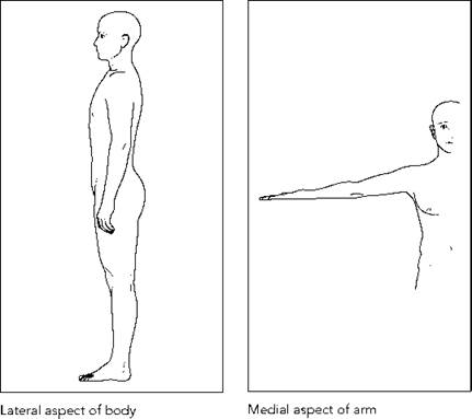
All the basic terminology descriptions below refer to the patient in the standard reference position, known as the anatomical position (see opposite).
Anatomical terminology
Patient aspect
• Anterior aspect: that seen when viewing the patient from the front.
• Posterior (dorsal) aspect: that seen when viewing the patient from the back.
• Lateral aspect: refers to any view of the patient from the side. The side of the head would therefore be the lateral aspect of the cranium.
• Medial aspect: refers to the side of a body part closest to the midline, e.g. the inner side of a limb is the medial aspect of that limb.


Positioning terminology
Planes of the body
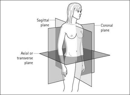
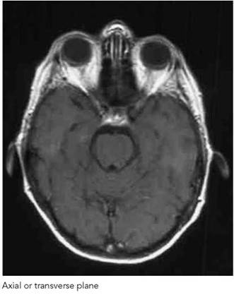
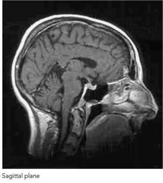
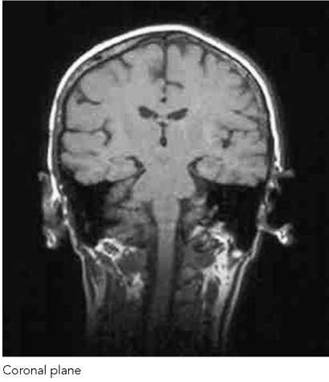
Three planes of the body are used extensively for descriptions of positioning both in plain-film imaging and in cross-sectional imaging techniques. The planes described are mutually at rightangles to each other:
• Median sagittal plane: divides the body into right and left halves. Any plane that is parallel to this but divides the body into unequal right and left portions is known simply as a sagittal plane or parasagittal plane.
• Coronal plane: divides the body into an anterior part and a posterior part.
• Transverse or axial plane: divides the body into a superior part and an inferior part.
Positioning terminology (contd )
This section describes how the patient is positioned for the various radiographic projections described in this text:
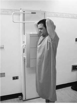
Erect: the projection is taken with the patient sitting or standing. In the erect position, the patient may be standing or sitting:
• with the posterior aspect against the cassette; or
• with the anterior aspect against the cassette; or
• with the right or left side against the cassette.
Decubitus: the patient is lying down. In the decubitus position, the patient may be lying in any of the following positions:
• Supine (dorsal decubitus): lying on the back.
• Prone (ventral decubitus): lying face-down.
• Lateral decubitus: lying on the side. Right lateral decubitus - lying on the right side. Left lateral decubitus - lying on the left side.
• Semi-recumbent: reclining, part way between supine and sitting erect, with the posterior aspect of the trunk against the cassette.
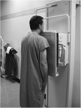
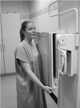
Erect: standing with the anterior aspect of the thorax against a vertical Bucky
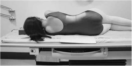
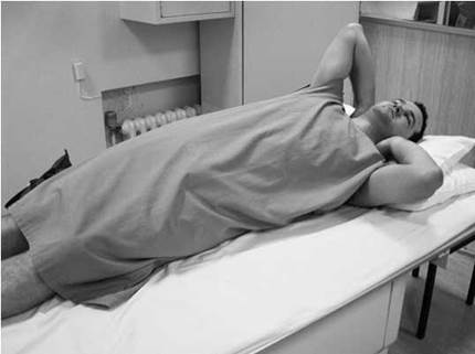
Left lateral decubitus: the median sagittal plane is parallel to the table and the coronal plane is perpendicular to the table
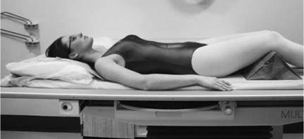
Supine: the median sagittal plane is at right-angles to the table and the coronal plane is parallel to the table

Prone: the median sagittal plane is at right-angles to the table and the coronal plane is parallel to the table
Positioning terminology
Right lateral erect: standing with the right side against a vertical Bucky
All the positions may be described more precisely by reference to the planes of the body. For example, ‘the patient is supine with the median sagittal plane at right-angles to the tabletop’ or ‘the patient is erect with the left side in contact with the cassette and the coronal plane perpendicular to the cassette’.
When describing positioning for upper-limb projections, the patient will often be ‘seated by the table’. The photograph below shows the correct position to be used for upper-limb radiography, with the coronal plane approximately perpendicular to the short axis of the tabletop. The patient’s legs will not be under the table, therefore avoiding exposure of the gonads to any primary radiation not attenuated by the cassette or the table.
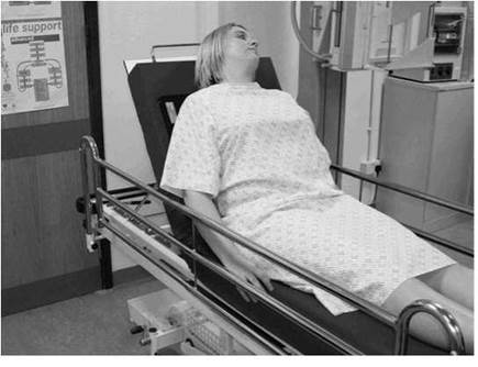
Semi-recumbent, with posterior aspect of the thorax against the cassette and median sagittal plane perpendicular to the cassette
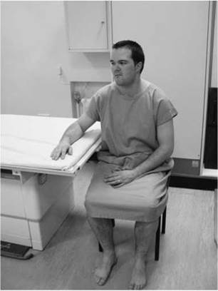
Correct patient position for upper-limb radiography with the patient seated
Positioning terminology (contd)
Terminology used to describe the limb position
Positioning for limb radiography may include:
• a description of the aspect of the limb in contact with the cassette;
• the direction of rotation of the limb in relation to the anatomical position, e.g. medial (internal) rotation towards the midline, or lateral (external) rotation away from the midline;
• the final angle to the cassette of a line joining two imaginary landmarks;
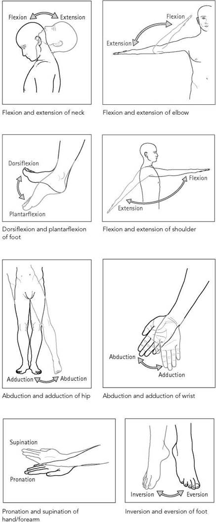
• the movements, and degree of movement, of the various joints concerned.
• Extension: when the angle of the joint increases.
• Flexion: when the angle of the joint decreases.
• Abduction: refers to a movement away from the midline.
• Adduction: refers to a movement towards the midline.
• Rotation: movement of the body part around its own axis, e.g. medial (internal) rotation towards the midline, or lateral (external) rotation away from the midline.
• Pronation: movement of the hand and forearm in which the palm is moved from facing anteriorly (as per anatomical position) to posteriorly. Supination is the reverse of this. Other movement terms applied to specific body parts are described in the diagrams.
A projection is described by the direction of the central ray relative to aspects and planes of the body.
Antero-posterior
The central ray is incident on the anterior aspect, passes along or parallel to the median sagittal plane, and emerges from the posterior aspect of the body.
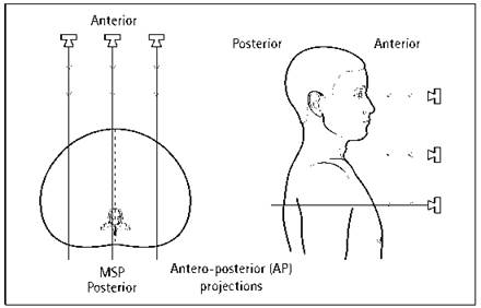
Postero-anterior
The central ray is incident on the posterior aspect, passes along or parallel to the median sagittal plane, and emerges from the anterior aspect of the body.

Lateral
The central ray passes from one side of the body to the other along a coronal and transverse plane. The projection is called a right lateral if the central ray enters the body on the left side and passes through to the image receptor positioned on the right side. A left lateral is achieved if the central ray enters the body on the right side and passes through to the image receptor, which will be positioned parallel to the median sagittal plane on the left side of the body.
In the case of a limb, the central ray either is incident on the lateral aspect and emerges from the medial aspect (latero-medial), or is incident on the medial aspect and emerges from the lateral aspect of the limb (medio-lateral). The terms ‘latero- medial’ and ‘medio-lateral’ are used where necessary to differentiate between the two projections.
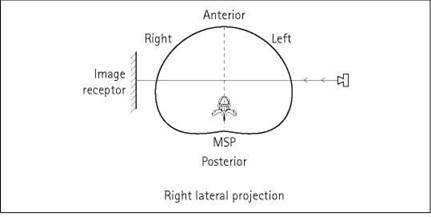
Beam angulation
Radiographic projections are often modified by directing the central ray at some angle to a transverse plane, i.e. either caud-ally (angled towards the feet) or cranially/cephalic angulation (angled towards the head). The projection is then described as, for example, a lateral 20-degree caudad or a lateral 15-degree cephalad.
Oblique
The central ray passes through the body along a transverse plane at some angle between the median sagittal and coronal planes. For this projection, the patient is usually positioned with the median sagittal plane at some angle between zero and 90 degrees to the cassette, with the central ray at right-angles to the cassette. If the patient is positioned with the median sagittal plane at right-angles to or parallel to the cassette, then the projection is obtained by directing the central ray at some angle to the median sagittal plane.
Anterior oblique
The central ray enters the posterior aspect, passes along a transverse plane at some angle to the median sagittal plane, and emerges from the anterior aspect. The projection is also described by the side of the torso closest to the cassette. In the diagram below, the left side is closest to the cassette, and therefore the projection is a described as a left anterior oblique.

Posterior oblique
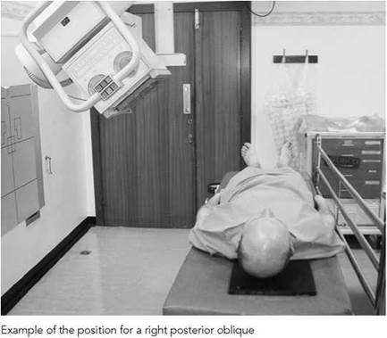
The central ray enters the anterior aspect, passes along a transverse plane at some angle to the median sagittal plane, and emerges from the posterior aspect. Again, the projection is described by the side of the torso closest to the cassette. The diagram below shows a left posterior oblique.

Oblique using beam angulation
When the median sagittal plane is at right-angles to the cassette, right and left anterior or posterior oblique projections may be obtained by angling the central ray to the median sagittal plane. (NB: this cannot be done if using a grid, unless the grid lines are parallel to the central ray.)

Example of left posterior oblique obtained using a beam angulation
Lateral oblique
The central ray enters one lateral aspect, passes along a transverse plane at an angle to the coronal plane, and emerges from the opposite lateral aspect.
With the coronal plane at right-angles to the cassette, lateral oblique projections can also be obtained by angling the central ray to the coronal plane. (NB: this cannot be done if using a grid, unless the grid lines are parallel to the central ray.)
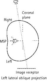
Example of lateral oblique obtained using a beam angulation

Projection terminology (contd)
The chapters that follow describe radiographic projections by reference to the following criteria:
• The position of the patient relative to the cassette.
• The direction and centring of the X-ray beam: this is given by reference to an imaginary central ray of the X-ray beam.
• Beam angulation relative to horizontal or vertical.
Examples of these are given below:
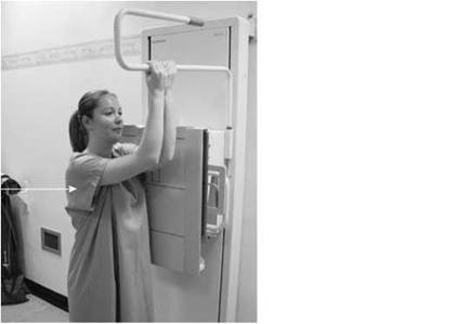

Projection: postero-anterior (PA)
Position: erect; anterior aspect facing the cassette and median sagittal plane at right-angles to the film
Direction and centring of X-ray beam: the central ray is directed horizontally (along the median sagittal plane) and centred to the spinous process of the sixth thoracic vertebra
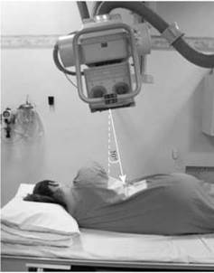
Projection: left lateral
Position: erect; left side against the cassette and median sagittal plane parallel to the cassette
Direction and centring of X-ray beam: the central ray is directed horizontally (at right-angles to the median sagittal plane) to a point 5cm anterior to the spinous process of the seventh thoracic vertebra
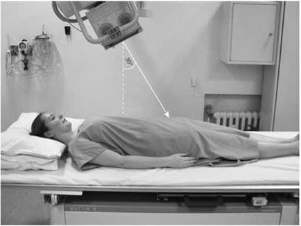
Projection: antero-posterior 30 degrees caudad Position: supine; median sagittal plane at right-angles to the table Direction and centring of X-ray beam: from the vertical, the central ray is angled 30 degrees caudally and directed to a point 2.5 cm superior to the symphysis pubis
Projection: left lateral 10 degrees caudad
Position: left lateral decubitus; median sagittal plane parallel to the cassette Direction and centring of X-ray beam: from the vertical, the central ray is angled 10 degrees caudally and directed (along a coronal plane) to a point in the mid-axillary line 7.5 cm anterior to the posterior aspect of the patient, at the level of the lower costal margin
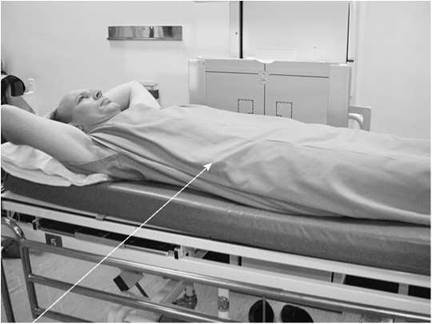
Projection: left lateral
Position: supine; median sagittal plane parallel to the cassette placed in a vertical Bucky against the patient's left side
Direction and centring of X-ray beam: the horizontal central ray is directed (at right-angles to the median sagittal plane) to the lower costal margin in the mid-axillary line
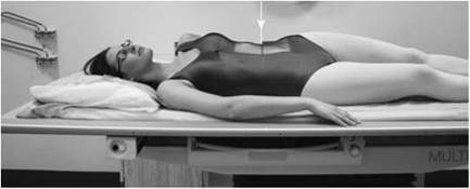
Projection: right posterior oblique
Position: supine and then rotated so that the left side is moved away from the table to bring the median sagittal plane at 45 degrees to the table Direction and centring of X-ray beam: the vertical central ray is directed to a point 2.5 cm to the right of the midline at the level of the third lumbar vertebra

Projection: postero-anterior
Position: left lateral decubitus; median sagittal plane parallel to the table and at right-angles to a cassette supported vertically against the patient's anterior aspect
Direction and centring of X-ray beam: the horizontal central ray is at right- angles to the posterior aspect of the patient in the midline (and passes along the median sagittal plane) at the level of the third lumbar vertebra
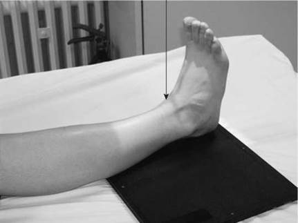
Projection: antero-posterior
Position: semi-recumbent or supine; leg extended fully; posterior aspect of the ankle in contact with cassette; lateral and medial malleoli equidistant from the cassette
Direction and centring of X-ray beam: vertical central ray directed to a point midway between the malleoli
Image formation
The X-rays used in medical diagnosis are produced from a small area within the X-ray tube when an exposure is made. They diverge outwards from this area, travel in straight lines, and can be detected by a variety of devices used for medical imaging.
As the X-rays pass through the body, some will be absorbed by the organs and structures within the body whilst others will pass through to the equipment used to form the image.
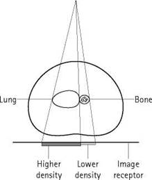
The term ‘density’ is often used in radiography. It can have different meanings depending on the context. In the diagram opposite, the X-ray beam enters the body and then encounters various structures. The bone has a high density because it has a relatively high mass per unit volume and consequently will absorb more X-rays than the adjacent area of lung. The lung contains air, which has a relatively low mass per unit volume and therefore can be said to have a low density. When the beam emerges from the body, there will be more X-rays directly under the area of lung compared with the area directly under the bone.
The image is then captured using an image-acquisition device. When a relatively large number of X-rays are incident upon the detector (e.g. the area under the lung), the image will appear to be quite dark and may be described as having a high image density. The area under the bone will appear lighter, since fewer X-rays will come into contact with the detector. This area therefore has a lower image density.
When examining an image for disease, the diagnostician may refer to a small focal area of disease as a density within the image. Rather confusingly, this could be of a higher or lower image density compared with the surrounding tissues, depending on the organ or tissue involved, e.g. a tumour in the lung (higher density) or bone (lower density, depending on tumour type).
In summary, the term ‘density’ can be used in the following ways:
• Patient or physical density: relates to the mass per unit volume of the structures within the patient and their absorption characteristics.
• Image density: the amount of signal detected in the image receptor or, put crudely, ‘blackening’ within the image. If measured on film using a densitometer, this will be optical density.
• In diagnosis: refers to a small defined area of pathology.
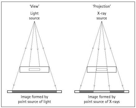
Projection and view
It is important to note that X-ray images are formed by projection, i.e. images of objects in the path of X-rays are projected on to a device for capturing the image, e.g. photographic material. This differs from the way in which images are formed on the retina of the eye or on the photographic film in a camera, where light travels from the object to the recording median to produce an image that is a view of the object; a radiographic image is a projection of the object.

Density and contrast
Density
The various uses of the term ‘density’ were discussed briefly in the previous section. When considering the radiographic image, the term ‘density’, as stated previously, can be defined crudely as the degree of ‘blackening’ within the image. The greater the amount of radiation that is incident upon the image detector, the greater will be the density within the image.
The general term ‘density’ can be defined more accurately when the type of image receptor is considered:
Photographic film
If the image is captured on a photographic emulsion, then the term ‘photographic density’ or ‘optical density’ should be used. Higher densities will be produced by greater exposures of radiation, which in turn leads to a form of silver being liberated from the photographic emulsion. This remains on the film after processing and produces the ‘blackening’ within the image. Photographic or optical density can be measured by determining the degree of opacity, i.e. the proportion of light absorbed by the processed film.

Radiograph produced on film, showing three different densities. The highest density is on the right of the image
Digital image capture
If the image was captured by a digital system such as computed radiography (CR) or direct radiography (DR), then the term ‘image density’ refers to the greyscale displayed on the monitor used to display the image. Put simply, it is the computer screen brightness.
The image-processing software will analyse the range of exposures that were captured by the image receptor (e.g. the CR phosphor screen). It will then assign the highest computer screen brightness to areas that have received relatively low exposures (low image density). Conversely, the lowest computer screen brightness (darkest areas) will be assigned to areas that have received a relatively high radiation exposure (high image density).
Contrast
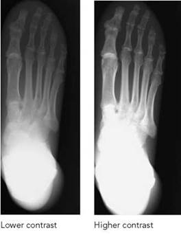
In order to detect pathology, an imaging system must be able to detect the differences in the density (patient density) of the pathology compared with that of the surrounding tissues. This must then be translated into differences in density within the final image (image or film density) that are visible to the observer. Contrast is the difference in density between structures of interest within the image. A low-contrast image will show little difference in density between structures of interest, whereas a high-contrast image will show a larger difference in density between structures.
The contrast seen on a radiograph is built up in three main stages:
• Subject contrast is a feature of the object (subject) under examination. The differences in radiation intensities emerging from the object result from the spatial distribution of linear attenuation coefficients within the object. At a given beam energy, the degree of beam attenuation between anatomical structures is determined by the physical density and atomic number of those structures. Subject contrast will change if the beam energy (kVp) is varied or via the use of a contrast agent, which will change atomic number within an area of the object.
• Radiographic contrast is the difference in optical density on different parts of the processed film or differences in computer screen brightness recorded as a result of the range of emergent beam intensities.
• Subjective contrast is the personal appreciation of the differences in optical density or computer screen brightness when the image is viewed.
Some of the factors that influence each of the above will now be considered.
Subject contrast
X-Radiation passing through the body is attenuated by different amounts by the different thicknesses, densities and atomic numbers of the structures in the body. The beam emerging from the patient varies in intensity: more will emerge if the beam encounters only a small thickness of soft tissue. The difference in intensities in the emergent beam is called subject contrast or radiation contrast.
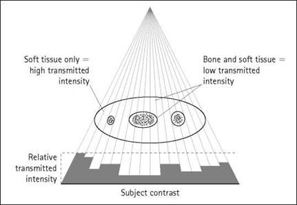
Factors that influence subject contrast include the following:
• The region of the body under examination: there is less subject contrast if all parts of the region have a similar linear attenuation coefficient. Soft-tissue structures such as the breast have a low subject contrast, whereas the subject contrast increases if the region includes bone or large differences in the thickness of tissue. A good example of an area of the body that demonstrates high subject contrast is the body and spinous process of a lumbar vertebra on a lateral projection of the spine and the lateral cervicothoracic junction.
• Contrast media: if high- or low-density/atomic number substances are introduced into cavities in a region, then there will be a greater difference in absorption of X-rays by different parts of that region and thus an increase in subject contrast.
• Pathology: if the density of a structure is changed due to pathology, then there will be a change in subject contrast; for instance, it will be reduced if the bone density reduces, as in osteoporosis.

• Kilovoltage: at lower kilovoltage, there is a greater difference in attenuation by structures of different density and atomic number than at higher kilovoltage. Therefore, at lower kilo- voltage, there is a greater subject contrast. This can be used to advantage when examining areas of low subject contrast, such as the breast. Conversely, there is a high subject contrast within the chest (marked differences in patient density when comparing the lungs and the heart). A higher kilovoltage will therefore reduce this subject contrast and produce a more even image density.
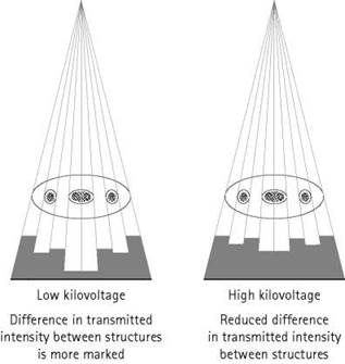
Low and high kilovoltage
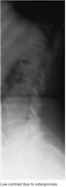
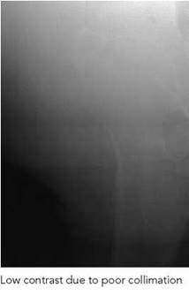
Subjective contrast
When a radiograph is viewed, the observer sees an image made up of different densities or brightnesses. However, different observers might have a different appreciation of the image contrast. The personal appreciation of the contrast in the image is called subjective contrast. Subjective contrast depends not only on the person but also on the viewing conditions. For example, if an image is viewed on a computer monitor and that monitor is placed near a window, then the sunlight incident upon the screen will severely impair the observer's ability to appreciate the density differences within the image. There may be good radiographic contrast but the observer cannot appreciate this because of the sunlight on the screen, so the subjective contrast will be low.
Subjective contrast depends on:
• the observer: visual perception, fatigue, etc.;
• viewing conditions: e.g. ambient lighting.
Radiographic contrast
After leaving the patient, the X-radiation passes to an image- capture device. As it passes through the body, some of the radiation will be scattered. Scatter reduces the differences in X-ray intensity emerging from different areas of the body and thus reduces contrast. The production of scattered radiation can be reduced by collimating the beam or by the use of compression devices. In each of these cases, this reduces the volume of tissue irradiated. In a large proportion of examinations, a secondary radiation grid is placed between the patient and the image- capture device to intercept a large proportion of the scattered radiation, which, if it were to reach the image detector, would reduce image contrast. Once the image has been captured, it can be viewed either on photographic film or by some electronic means such as a computer monitor. The different patient densities are recorded either as varying photographic densities or as differences in computer screen brightness. These different densities can be measured either using a densitometer or image- analysis software to give an objective measurement of contrast. Thus, differences in measured image density between specified parts of the radiographic image are known as radiographic or objective contrast.
Density and contrast (contd)
Radiographic (objective contrast) depends upon the following:
• Subject contrast.
• Scattered radiation reaching the image receptor: the use of a secondary radiation grid between the patient and the cassette to reduce the scatter reaching image receptor improves radiographic contrast. Lead-backed cassettes or lead rubber under cassettes may reduce back-scatter, which may also improve radiographic contrast. If the cassette is some distance away from the patient, then scatter crossing the intervening gap might not reach the image receptor.
• Image-acquisition device: the design and function of the device used to acquire the image can have a profound effect on contrast. For example, certain types of film emulsion, intensifying screen and phosphor plate may be designed to give inherently greater contrast. In digital systems, the contrast is also influenced profoundly by the software used to process the initial image captured by the device.
• Film fog: if the image is viewed using a photographic-based system, then film fogging due to incorrect film handling or storage may reduce radiographic contrast.
• Exposure: if too much or too little radiation is used, then the image-acquisition device may be unable to respond or may be saturated to the point that it is unable to function properly. In these examples, there may be a reduced range of densities or no difference in density visible on the image, thus radiographic contrast will be reduced or non-existent.
• Development: if a photographic emulsion is used to capture the image, then optimum radiographic contrast can be attained only if the film is developed to the correct film contrast. This is achieved by careful control of factors such as developer temperature, development time and processing chemical activity. To ensure this, the film processor must be subject to a rigid quality-control regime.
Subjective contrast depends upon the following:
• Radiographic contrast.
• The observer: poor eyesight, fatigue.
• Viewing box: brightness, evenness and colour of illumination.
• Computer monitor: many factors related to the quality of construction and design of the monitor will influence the contrast visible to the observer.
• Ambient lighting: if the room lighting is low and there is a reduction in extraneous light reaching the eye, then subjective contrast will improve. Radiographs are often viewed under poor conditions in hospital, especially in the ward environment. Radiographers have an important role in educating all hospital staff as to the benefits of viewing radiographs under proper lighting conditions.

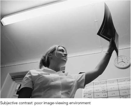
Magnification and distortion

Magnification
In a projected image, magnification will always be present because the X-rays continue to diverge as they pass from the object to the image-acquisition device (henceforth referred to as a film for simplicity). The source of the X-rays is the X-ray tube focal spot. For a given focus-to-film distance (FFD), the greater the distance between the object and the film, the greater will be the magnification of the image. To minimize magnification, the object under examination should be positioned as close to the film as is reasonable to do so.

where FOD is the focus-to-object distance.
If the object-to-film distance has to be increased, e.g. in the case of a patient on a trolley, then the FFD can also be increased. This will then reduce the magnification caused by the above. (NB: an increase in exposure will be needed in this case due to the effect of the inverse square law on the beam intensity).
Image distortion
A distorted image will be produced if not all parts of the image are magnified by the same amount. Considering a thin, flat object, there will be constant magnification and thus no distortion when the film is parallel to the object. When possible, the part being radiographed should be placed parallel to the film to avoid distortion. If the object and film are not parallel to each other, then there is a difference in magnification of different parts of the object, leading to a distorted image.
In the diagrams opposite, the object and film are not parallel to each other. It can be seen that if the centre of the X-ray beam is directed at right-angles to the object but the object is not parallel to the image receptor, then a distorted, elongated image is produced. If the centre of the beam is directed at right-angles to the image receptor but is angled in relation to the object, then a distorted, foreshortened image will be produced.
In cases when the object and film cannot be parallel to each other, a compromise can be made by directing the central ray at right-angles to an imaginary line bisecting the angle between the object and the film. Although distortion does occur, the net effect is neither elongation nor foreshortening of the image. This technique may be required if a patient is unable to straighten a limb to bring it parallel to the film when imaging a long bone.
Image sharpness
In radiography, the aim is to produce an image that is as sharp as possible in order to resolve fine detail within the image. This is particularly important when looking for subtle fractures or changes in bone architecture.
Unfortunately, there are several factors that lead to image unsharpness. These are unsharpness due to:
• geometry (Ug);
• movement (Um);
• absorption (inherent factors) (Ua);
• photographic/acquisition factors (Up).
Geometric unsharpness
If X-rays originated from a point source, then a perfectly sharp image would always be obtained. In an X-ray tube, however, the X-rays are produced from the small area of the focal spot on the anode. As can be seen from the diagram opposite, this leads to the formation of penumbra or ‘partial shadows’ at the edge of the object; it is this that gives rise to geometric unsharpness.
The degree of geometric unsharpness increases with an increased focal spot size and increased object-to-film distance:
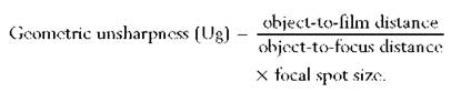
Geometric unsharpness can be a small, insignificant quantity if the object is close to the film and a small focal spot is used. For instance, with a postero-anterior projection of the wrist, where the maximum object film distance is about 5 cm, and if a normal FFD of 100 cm is used, then geometric unsharpness is only 0.05 mm using a 1-mm focal spot and only 0.1 mm with a 2-mm focal spot. When thicker parts of the body are being examined, which might require the use of a larger (broad) focal spot, then geometric unsharpness can make a significant contribution to total image unsharpness owing to the greater object-to-film distance.
Movement unsharpness
This type of unsharpness is due to patient, equipment or film movement during the exposure. Patient movement may be involuntary, e.g. owing to heartbeat or peristalsis, or it may the type of movement that may be controlled by immobilization. It is important to note that any patient movement is magnified on the image because of the space between the moving object and the film. Sharpness can be increased by using a shorter exposure time (achieved by a lower mAs with higher kVp, higher mA, or greater tube loading), by a small object-to-film distance and particularly by immobilization.
Various accessories can be used for immobilization, including non-opaque pads and sandbags to immobilize the extremities.
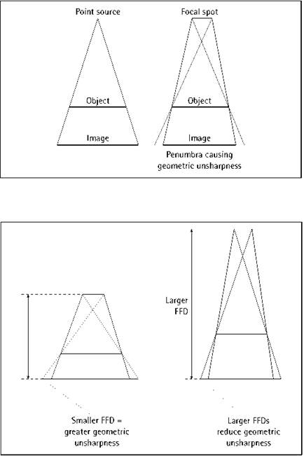


Image sharpness
Binders and Velcro straps may be used for the trunk and head. These accessories should be available in all examination rooms and should be used routinely. It is equally important to make the patient as comfortable as possible and to explain the procedure fully. The radiographer can also invite questions about the procedure, thus increasing the likelihood of achieving full cooperation from the patient. It may be worthwhile rehearsing respiratory manoeuvres prior to an actual exposure being made.
Absorption unsharpness
This is due to the shape of the structures in the body. As illustrated, unless the structure has a particular shape, with its edges parallel to the diverging beam, then absorption of the X-ray beam will vary across the object. Considering a spherical object of uniform density, then absorption will be greatest at the centre and least at the periphery due to the difference in thickness. This gradual fall-off in absorption towards the edges leads to the image having an ill-defined boundary called absorption unsharpness, particularly as most structures in the body have a round edge. Little can be done to reduce this type of unsharpness, apart from increasing image contrast or using digital edge-enhancement techniques.
Photographic unsharpness
An X-ray image could be formed by the direct action of X-rays on a photographic emulsion, but more usually the X-ray image is first converted into a light image by intensifying screens. This increases the photographic effect of the X-rays and thus allows exposure to be greatly reduced. The intensifying screens contain crystals that fluoresce when irradiated by X-rays. Photographic unsharpness is the spread of light between the crystals and the photographic emulsion. The spread of light will be greater with larger crystals (regular or fast screens) and will also be greater with increasing distance between the crystal and the film (poor film/screen contact). Duplitized film with the emulsion on both sides of the film base is commonly used to decrease the exposure given to the patient, but the unsharpness will be greater than if a single-sided emulsion is employed. This is caused by the image on one side of the emulsion crossing over to the other side. As it does so, the light diverges and produces an image slightly larger than the image on the opposite side. Another possible cause of unsharpness in duplitized films occurs when the final image is viewed. If the observer is in such a position that the images on each side of the emulsion are not exactly superimposed, this introduces further unsharpness known as parallax.
Photographic unsharpness is reduced by ensuring that all cassettes maintain good film/screen contact and by using finegrained screens or single-sided emulsions when appropriate. The least photographic unsharpness occurs when intensifying screens are not used, but this is unjustifiable for the majority of radiographic examinations.
Complex formulae have been given to calculate the total unsharpness due to several contributory factors. These show that if any one type of unsharpness is much greater than the others, then only by reducing that type will any significant improvement be made in image sharpness. For example, when dealing with a restless patient, the greatest source of unsharpness will be the patient movement, and image sharpness will not be improved visibly by reducing other sources of unsharpness.
A summary of the methods used to reduce different types of unsharpness is shown in the table below.
Unfortunately, the factors in group A are interrelated, and attempts to reduce one form of unsharpness will tend to increase another. For example, if one chooses to use fine-grained screens to reduce photographic unsharpness, then an increase in mAs may be required, which could lead to a longer exposure time, thus increasing the possibility of movement unsharpness. This increase in mAs may in turn require an increase in focal spot size due to the additional thermal stresses on the anode, and there will be an increase in geometric unsharpness as a consequence of this. Choice of factors in group A is part of the radiographer's skill. If movement unsharpness will be a predominant factor, e.g. with a restless patient, then it must be reduced, perhaps by using a higher tube loading on the broad focus or by the use of the faster intensifying screen to reduce exposure time. In the former situation the geometric unsharpness will increase, and in the latter situation photographic unsharpness will increase. If the patient can be fully immobilized, then the above strategies may not have to be used and an image with a greater degree of sharpness will be obtained.
If we examine the factors in group B, we find that reducing any type of unsharpness with these does not cause another type of unsharpness to increase. For example, by having good/film screen contact, then neither movement nor geometrical unsharpness is increased. There is no increase in geometrical unsharpness or photographic unsharpness if the patient is immobilized.
To obtain the sharpest image possible, we must make a judgement about the factors in group A. We have to decide whether we will use the broad or fine focus, fine-grain or regular/fast screens. But there are no decisions to make about the factors in the group B. We should always strive to position the part under examination as near as possible to the cassette, to immobilize the patient in as comfortable position as possible, and to give the patient clear instructions and check their understanding of these instructions. All film cassettes should be maintained to ensure good film/screen contact, and other imaging equipment should be maintained regularly.

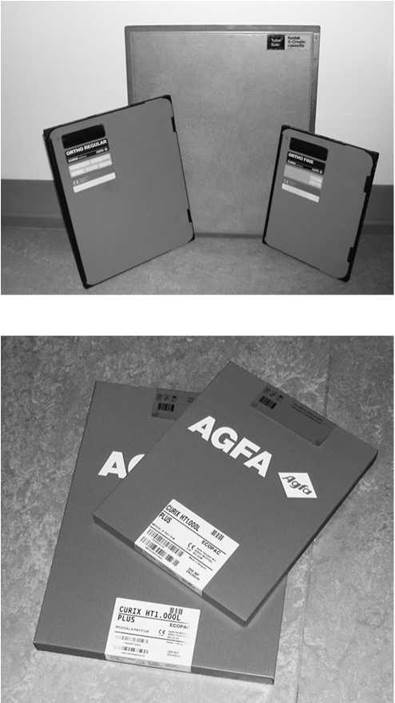
Image acquisition and display
Images can be acquired in several different ways depending on the equipment used by any particular imaging department. These are:
• conventional film/screen technology;
• fluoroscopy/fluorography;
• digital imaging:
- computed radiography (CR);
- direct digital radiography (DDR).
Each of the above will be considered briefly.
Conventional film/screen technology
At the time of writing, this is the cheapest and most versatile method of image capture. Photographic film is capable of storing an image alone, but the exposure required can be reduced considerably if the film is placed between intensifying screens that convert the X-ray energy into light, which in turn exposes the film. The film and cassettes are widely available in a variety of sizes and can be used with almost any piece of imaging equipment.
An image captured on photographic film will have high resolution, although it has narrower exposure latitude compared with other image-capture systems. This means that the radiographer has much less margin for error when selecting exposure factors before making an exposure. It is relatively easy to overexpose or underexpose an image compared with other image-acquisition devices.
A variety of systems are available in which the screen and film can be varied to suit a particular task. Thus, the speed and resolution can be changed in any given clinical situation by selecting a different film and screen. Graduated or asymmetric systems have been used to enhance spine and chest radiography, where the subject contrast is high.
X-ray film is highly portable, although a considerable amount of space is required to store the film bags.
A series of X-ray film processors are required in a department using conventional imaging technology. These must be regularly cleaned, serviced and subjected to a rigorous quality-control programme in order to ensure consistency of performance.
Fluoroscopy/fluorography
This method of image acquisition employs an image intensifier to capture images, which are then displayed in real time or as static images on a monitor. Fluoroscopy is very useful for following the progress of contrast agent around the body, but its resolution is poor compared with that of other image-acquisition methods so it is not currently used for plain radiographic imaging. Fluorography employs photographic film to capture the image from the image intensifier. This method has now been largely superseded by digital image-capture methods.
Introduction
Film/screen imaging in radiography is gradually being replaced by digital imaging. There are many advantages to digital imaging; the workflow should be faster, and it allows image processing to optimize the clinical information from an image.
Advantages of digital systems
Digital imaging exhibits a number of advantages when compared with conventional film/screen imaging:
• increased latitude and dynamic range;
• acquisition and display are separate processes;
• images can be accessed simultaneously at any workstation;
• viewing stations can be set up in any location;
• ability to use digital image archives rather than film libraries;
• images will generally be quicker to retrieve and less likely to be lost;
• ability to post-process images to aid visualization of anatomy and pathology;
• availability of soft-copy reporting;
• no manual handling of cassettes for direct digital radiography (DDR) systems;
• potential patient dose reduction;
• potential lower running costs, providing only soft-copy reporting is used;
• no handling of processing chemicals.
Uses
CR is used in all areas where film/screen systems are currently used, including mammography. DDR can be used in general radiography and mobile radiography. DDR is very popular in small-field mammography and is being introduced into full-field mammography. DDR detectors are now being used instead of image intensifiers in fluoroscopy.
Image acquisition
Technology overview
There are a number of technologies used for digital imaging in planar radiography. They can be divided into CR and DDR.
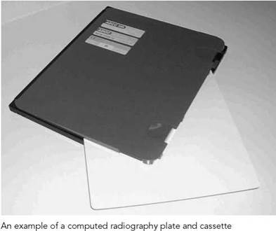
CR is, in first appearance, similar to the use of a film/screen system. The CR plate is in a cassette, which will fit the table and vertical Bucky trays and can be used with mobile equipment. The plate is then scanned in a reading system similar in size to a daylight processor. This therefore makes the change to digital radiography easier.
A DDR system entails more changes in X-ray couch and vertical Bucky design and often changes to the X-ray tube assembly. Unlike the removable CR cassette, the DR plate or detector is fully integrated into the exposure equipment. The patient is radiographed and the image appears on the acquisition workstation in a few seconds. Here, the image can be optimized and then sent for reporting or repeated if necessary.
Computed radiography technology
The active phosphor layer of a CR plate usually comprises a layer of europium-doped barium fluorobromide, which is coated on to a semi-rigid or flexible polyester base. X-ray photons are absorbed by the phosphor layer, and the phosphor electrons become ‘excited’ and are raised to a higher energy level, where they can stay trapped in a semi-stable higher-energy state. The trapped electrons represent a latent image in the phosphor plate in the form of ‘stored energy’. The stored energy can be released by adding energy to the trapped electrons. This is done by stimulation with a laser beam. The trapped electrons then ‘escape’ from the traps to fall back to their equilibrium state. As they fall back, the electrons release energy in the form of light. This phenomenon is otherwise known as photostimulable luminescence (PSL). The emitted light intensity is proportional to the original X-ray intensity. The light energy is detected and the signal is digitized. These data are processed digitally to produce a visible diagnostic image on a monitor. The phosphor plate is then ‘erased’ with a bright white light to remove any remaining trapped electrons, and the plate is then ready for the next examination.
Digital radiography technologies
The main detector technologies used in digital radiography are:
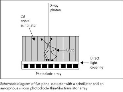
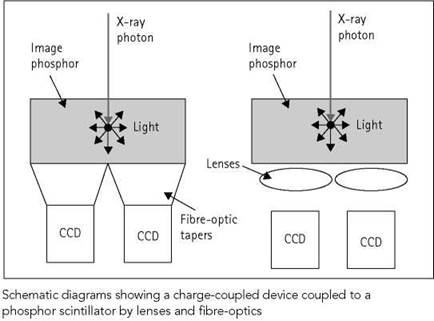
• X-ray scintillator bonded to a read-out array (amorphous silicon photodiode/thin-film transistor (TFT) array) or coupled to a charge-coupled device (CCD);
• X-ray detector of amorphous selenium bonded to a TFT readout array.
Both types can be constructed in the form of a flat panel.

Digital imaging 1
Image acquisition
Scintillator detector
The X-ray detector is normally a scintillator of thallium-doped CsI(Tl) crystals, although other phosphors such as Gd2O2S are also used. The scintillator converts the X-rays into a light output. The CsI has a columnar crystal structure that guides the light to the read-out device, which allows the CsI to be thicker than a phosphor powder without significantly increasing unsharpness. As with phosphors in film cassettes, thinner powder phosphors (such as Gd2O2S) will have lower unsharpness. Gd2O2S phosphors are thinner than CsI scintillators, but they have higher conversion efficiency.
Scintillators are usually coupled directly to an amorphous silicon photodiode TFT flat-panel read-out array. The light from the scintillator is converted into electrical charge in a photodiode array, which stores the charge until it is read out from each of the pixels. These are commonly referred to as amorphous silicon systems.
Charge-coupled device
The light output from the scintillator detector can be read out by a CCD camera. The CCD is generally smaller than the phosphor, and so it is usually coupled using a lens or fibre-optic bundles. Demagnification may be necessary, and this can result in a loss of sensitivity if the demagnification is high.
Amorphous selenium/thin-film transistor flat-panel detector
The detector consists of a layer of amorphous selenium with a matrix of electrodes on each face. The X-ray energy produces electron-hole pairs in the selenium layer, which are attracted towards the electrodes by an electric field. The charge is collected and read out using a TFT array. The resolution of this type of detector is better than that using a phosphor due to the absence of light scattering.
Scanning technology
An alternative detection method for covering the full image area is to use slot-scanning technology. A linear array of detectors scans across the patient in conjunction with a narrow-fan X-ray beam. This method may result in good scatter rejection and contrast differentiation, but it has a number of disadvantages, including a long exposure time and high tube loading. Also, the alignment of the scanning radiation beam and the detectors requires tight mechanical tolerances and mechanical stability of the scanning mechanism.
Factors affecting image quality
There are a number of factors, both inherent in equipment design and external, that affect image quality. The following are important examples:
Fill factor
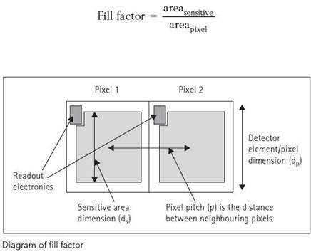
For flat-panel detectors, a proportion of the detector contains the read-out circuitry and will be insensitive to the incoming light photons or electrons. This leads to the concept of the fill factor (see equation below), which is the ratio of the sensitive area of the pixel to the effective area of the detector element itself.
Any improvements in resolution will require a reduced pixel pitch. The fill factor will decrease with improved resolution, as the read-out electronics will take up a larger proportion of the detector element and decrease the detector sensitivity.
Tiling
A tiled array consists of a number of detectors abutted together to sample the whole image. However, there may be small areas on read-out devices that are not sensitive; these are caused by gaps between the detectors (typically about 100 gm). There may be some image processing to compensate for this, although this may give some stitching artefacts.
Grids
Low grid strip densities can cause interference patterns in the image called Moiré patterns. This can be solved by using moving grids or high-density grids of over 60lines/cm. When using CR, ideally the grid lines should also be perpendicular to the scan lines in the reader.
Radiation exposure (image optimization)
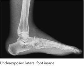
Image quality is related to the radiation exposure received by the detector. Although a relatively low exposure will result in a noisy image, it may still contain sufficient information to be diagnostically acceptable. A high exposure will result in improved image quality, since quantum noise is reduced. However, imagequality improvement is not linear: it will eventually level off as the quantum noise becomes less dominant and decrease as the plate becomes overexposed. Ideally, a system should be set up to obtain adequate image quality for the lowest possible dose (optimization).

Automatic exposure control response
An automatic exposure control (AEC) for a film/screen system is set up by ensuring that the correct optical density is achieved across a range of kilovoltages. This method is not practical for digital imaging, as the image will be displayed according to preset parameters, irrespective of the exposure used. The AEC will need to be set up in collaboration with the radiology and medical physics departments and the supplier. The level of exposure must be optimized for the selected examination and the receptor dose measured.
One other consideration is that sometimes when film/screen systems are replaced by a CR system, then for simplicity the AEC is kept at the same settings. This may not be the optimal working level, because the sensitivity and energy response of the digital system are different from those of the film/screen system it replaces. A DDR system can use the detector itself as an AEC, although currently most use a conventional AEC chamber system.
Bit depth/image size
A pixel is the smallest element of a digitized picture. A smaller pixel size will generally give an improved spatial resolution in the image. The pixel pitch is the distance between the centres of adjacent pixels.
The matrix size is the number of pixels or memory locations into which the image is divided. Thus, the total number of pixels in a 1024 X 1024 matrix is 1 048 576, defined as one megapixel.
The bit depth of the image determines the contrast resolution. The analogue value of the output from each pixel is converted to digital form, and the results are stored at a separate location in a matrix. The number of grey levels available equals two to the power of the number of bits, e.g. 28 = 256.

Clinical images require good contrast resolution, which is difficult to achieve due to the noise inherent in a radiographic image. In order to achieve good contrast resolution, high bit depths are required. The number of bits required depends on the noise level: the lower the level of noise, the higher the number of bits that can be used.
Networking
So far, the digital-acquisition technology has been discussed. However, the great advantage of digital imaging is to be able to integrate it into a health community-wide system. Linking the digital X-ray into the hospital information system (HIS) and radiology information system (RIS) and storing the images on a Picture Archive and Communications Systems (PACS) system enables images to be reviewed at various reporting rooms, consultants’ offices, wards, etc. Images can also be reported off site using teleradiology (see p. 27 for summary of components and workflow).
Hospital information systems and radiology information systems
HIS and RIS contain patient details and examination information. If the digital acquisition system and PACS is connected to a HIS/RIS, then the workflow of a department can be increased by using the RIS data to control workflow, thereby delivering improved patient throughput. For instance, by automatically attaching patient demographic and examination details from the RIS to the image, images can be delivered to the correct destination much faster. Reporting, storage and retrieval can also be made more efficient. HIS/RIS systems typically use the Health Level 7 (HL7) standard to transfer patient details.
Networking
Digital Imaging and Communications in Medicine (DICOM)
Digital Imaging and Communications in Medicine (DICOM) Version 3.0 is a protocol-based standard to facilitate the transfer of digital images and associated information between devices manufactured by a range of vendors and to aid in the development of PACS.
When purchasing a system, a DICOM conformance statement should be received, which will inform how the device and software conform to the standard for its particular function. If a modality does not produce images in DICOM format and it cannot be upgraded to DICOM, then a DICOM secondary capture device will be needed to convert the image to a DICOM- conformant image (secondary capture only) and allow the system to be connected to the PACS.
Picture Archive and Communications System
PACS is an image-management and communication system. It stores and distributes images and information around the system. It is connected to each of the digital acquisition systems and other modalities in order that images and information can be transmitted to their appropriate destinations. Patient data from the HIS/RIS system are used to correctly route and retrieve images, and printers are used to produce hard copy if needed.
A PACS can range from so-called ‘mini-PACS’ systems serving just one or two imaging modalities with perhaps only one reporting workstation to enterprise-wide PACS handling all image data with multiple reporting and speciality workstations and image distribution to all necessary locations throughout the hospital and beyond. There are many PACS models; a simple schematic diagram for a typical radiology department is shown on the next page.
Images will be viewed at various points in the system. The extent to which these images can be manipulated will depend on the type and function of the equipment. Typical viewing components include:
• acquisition, reporting and viewing workstations;
• monitors;
• laser printers.
Acquisition and reporting workstations
The acquisition workstation is where the data are initially received and pre-processing will be undertaken. This is true for some manufacturers, but with others this happens within the CR reader. Ideally, if the CR system has been calibrated and operated correctly, the image that appears should not require further processing.
Reporting workstations can be a component of the PACS or can be dedicated to a digital unit. In either case, these will be high- specification workstations with a comprehensive range of postprocessing facilities.
Networking (contd)
Monitors
At the time of writing, the maximum light out of a video monitor is limited, so that it is advisable to specify the ambient light when measuring performance. In order to perceive two adjacent areas as black and white respectively, it is necessary for the areas to have a difference in brightness of the order of 30 : 1.
The blackest area in the picture should have a brightness that is approximately the same as the light reflected back to the observer from the unilluminated cathode ray tube (CRT) face. This will depend on the ambient light level, the colour of the phosphor, and the filtration of the glass.
The ambient light level can be measured by standing in the normal viewing position and pointing a spot photometer at the centre of the CRT screen with the monitor turned off. The reading should fall between 1 and 10Cd/m2. The idea value would be 3.3Cd/m2, but it would be difficult to adjust the ambient light level with this degree of accuracy.
The limiting resolution of the monitor is dependent upon the CRT cathode current and, therefore, brightness. As a rough guide, a good-quality monitor should be capable of generating a high-quality image when the maximum large area brightness is about 100 Cd/m2.
Laser printers
The image can be printed on a laser printer for remote departments. However, to get the full benefits of a digital system, images should be reported on soft copy. It should be noted that laser film is more expensive than standard radiography film.
Look-up table
An LUT converts each pixel value into a new value. An LUT has two main uses:
• A digital detector generally has a much wider dynamic range than the range of intensities in a clinical image, and therefore an LUT is used to compress the data to cover only the clinically useful data.
• An LUT may be a curved rather than a linear relationship to enhance the contrast in the clinically useful densities. There may be a range of curves suitable for different clinical examinations.
The graph below shows an example LUT compressing a 12-bit image to a 10-bit image and applying a characteristic curve.
Compression
Compression of the image dataset is achieved using a processing algorithm. Compression of images is useful because the smaller an image, the more that can be stored for a given archive and the faster the transmission. Compression can either be lossless or lossy. Reconstruction of the image from a lossless compression will be the same as the original image, while a lossy image will have some changes. Some systems, although lossy, will claim to be ‘visually lossless’, i.e. there is no perceptible difference between the original and the reconstructed image. Compression ratio is defined as the ratio of the image size to the compressed image size, such that a 4:1 compression has reduced the image size by a factor of four.
Image processing
Ideally, the acquisition workstation should enable the following:
• addition of anatomical markers;
• demographics correction;
• image annotation;
• window and level adjustment;
• electronic collimation;
• magnification;
• application of different look-up tables (LUTs).
The reporting workstation will be a high-specification workstation with a comprehensive range of post-processing facilities, which include most of those listed previously (not addition of markers and LUTs), plus other functions, including:
• edge enhancement;
• noise reduction;
• tools for measuring pixel values, distances and angles;
• zoom and roam.
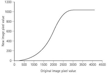
Example of a look-up table (LUT)
Typical PACS components and workflow


Each time a radiograph is to be produced, a set of exposure factors has to be chosen to give the type of image required. The choice of these factors will depend on the region being examined, including its thickness, density, pathology, etc. The exposure factors to be selected are:
• the milliampere seconds (mAs);
• the kilovoltage;
• the FFD.
The exposure factors chosen will differ for different types of image-acquisition device and will depend on whether a grid is being used.
Milliampere seconds
This indicates the intensity or, put simply, the amount of radiation being used. If the radiation has enough energy to penetrate the body, then it will be detected by the image-acquisition device and will determine the image density or, again put simply, the image ‘blackening’.
mAs is a product of the X-ray tube current (mA) and exposure time (seconds). As a general rule, the mA should be as high as possible with a short time, to reduce the risk of movement unsharpness. The X-ray generator will automatically select the highest mA and lowest time that is consistent with an acceptable amount of thermal stress upon the tube. The radiographer does, however, have the option of increasing this tube loading to give a shorter time and higher mA should the clinical situation demand this, e.g. in the case of a restless patient.
If insufficient mA is used, then a photographic film will be underexposed and will lack photographic density and therefore will show reduced contrast. If an electronic image-acquisition device is used, then an insufficient mAs will manifest itself as noise or mottle, even though the image-processing software will have produced a computer screen brightness (image) density that appears adequate. A mAs level that is too high will result in an overexposed film with excessive density and, again, a lack of contrast. In the case of a digitized electronic image-acquisition system, an increasing mAs will produce images that are of increasing quality with progressively less noise and improved signal-to-noise ratio.
Kilovoltage
This indicates how the X-ray beam will penetrate the body. The range of kilovoltages used in diagnostic radiography is normally between 50 and 120 kVp, although a kilovoltage as low as 25 kVp may be used for certain soft-tissue examinations, such as mammography. High-kVp techniques, such as those used in chest radiography, employ a kilovoltage in excess of 120 kVp.
The kilovoltage will have a profound effect on the image density.
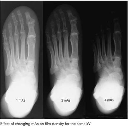


As the kilovoltage increases, the X-rays produced have a higher energy and more will be able to penetrate the body. This will be detected by the image-acquisition device.
Kilovoltage is also the most important factor in the control of contrast of the radiographic image and should therefore be chosen carefully.
The kilovoltage should be such that the radiation has enough energy to penetrate the body part and reach the image-acquisition device. Maximum contrast will be achieved if the lowest possible kVp is used which will allow a reasonable proportion of the radiation to penetrate the body part. Dense structures within the body (e.g. bone) will absorb these low-energy X-rays, but structures of lower density (e.g. soft tissue) will absorb relatively few X-rays. This leads to a large difference in image density between these structures, i.e. high contrast. As the kilovoltage increases, proportionately more radiation will be able to penetrate the denser body part compared with the less dense part. The resulting difference in density between the two images will be reduced, giving a lower-contrast image.
If there is a very wide range of patient densities within the region being examined (e.g. the chest), then the image may show excessive contrast and it might be necessary to reduce the contrast within the image to allow a diagnostic image density to be attained throughout the region of interest. This can be achieved by increasing the kVp and, as mentioned previously, is commonly undertaken in chest radiography.
Another reason for increasing the kVp is to allow the mAs, and therefore the exposure time, to be reduced. As kilovoltage is increased, not only does the radiation have more energy but also more radiation is produced, thus allowing the reduction in mAs. This reduction in exposure time will, however, be at the expense of image contrast.
Focus-to-film distance
For a given kVp and mAs, the greater the FFD, the lower the intensity of radiation reaching the film. Therefore, to obtain the same film blackening, if the FFD is increased the mAs must also be increased.
When choosing the FFD, the following factors are taken into consideration:
• The X-ray tube must not be too close to the patient’s skin, otherwise radiation damage could be caused.
• Short FFDs could give unacceptable geometric unsharpness.
• The FFD must not be excessive, otherwise the large increase in mAs required would mean high tube loading.
Most radiographic examinations are carried out with an FFD of 100 cm, which gives acceptable focus-to-skin distance and geometrical unsharpness but does not put unnecessary thermal stress on the X-ray tube. If this is the customary FFD used, then the department will require grids focused at 100 cm.
Focus-to-film distance (contd)
If there is a large object-to-film distance, FFD is sometimes increased to reduce geometrical unsharpness and magnification.
To calculate the new exposure at the changed distance, the following formula can be used:

For example, if at 100 cm FFD an exposure of 65kVp and 20 mAs produced a satisfactory result, then at 200 cm FFD, the new mAs would be calculated as follows:

Therefore, the exposure factors required at an FFD of 200 cm will be 65 kVp and 80 mAs.
Intensifying screens
Intensifying screens used in conjunction with photographic film are usually in pairs, with the film sandwiched between them and contained in a rigid, light-tight container, i.e. a cassette.
Different types of intensifying screen emit different intensities and different colours of light when irradiated by X-rays. It is important to ensure that the type of film used with a particular type of screen is matched in terms of the colour of light it is most sensitive to.
‘Fast’ or regular screens require less radiation to produce the same film blackening than the ‘slow’ screens used for extremity radiography. When changing from slow to fast screens, the exposure must be reduced. This has the advantage that a lower radiation dose is received by the patient; however, greater screen speed will result in greater photographic unsharpness, with a resultant decrease in image quality. It is important to consult the screen manufacturers’ guidelines to become aware of the difference in speed of the particular screens used in a particular department.
Digital image capture
If a digital method of image acquisition is being used, such as CR, then a wide range of exposures will produce an image. If the equipment does not receive an optimal exposure, then the image will show noise or mottle and will not be suitable for diagnosis. Exposures over a given optimum will still produce an acceptable image up to a point, but the patient will have been exposed to a radiation dose that is unjustifiable.
The equipment used for digital image acquisition should have some indication of how much exposure was used in for a particular examination. The radiographer should consult this and compare the value with the optimal range of values recommended by the manufacturer.

FFD increased to reduce increased geometric unsharpness from a large OFD

Effect on image density when using different screen types
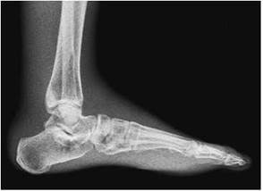
Underexposed digital image

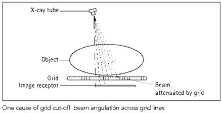

Secondary radiation grid
Grids are used when the thicker or denser parts of the body are being examined, where scattered radiation is likely to reduce significantly the contrast of the image. A grid, either stationary or moving, is placed between that patient and the cassette. Its design allows a high percentage of primary radiation to pass to the film while absorbing a high percentage of scattered radiation.
Because the grid stops both primary and secondary radiation, mAs must be increased when a grid is used. The increase required is generally by a factor of two to four, but this may vary considerably with the type of grid used.
Grids are usually focused (e.g. at 100 cm), which means that the X-ray tube should be at this distance (e.g. 100 cm) above the grid for maximum transmission of primary radiation through all parts of the grid.
With a low-ratio grid (the ratio between the height of lead strips to the width of the strips) and a small field size, this distance is not critical and the tube could be some 20-30 cm above or below the grid focus without any noticeable effect on the radiographic image. If, however, a high-ratio grid is used (14:1 or 16:1) with a large field size, then the X-ray tube must be within a few centimetres of the grid focus, otherwise there will be a loss of image density at the two edges of the film that were parallel with the grid slats.
The central ray of the X-ray beam can be angled along the line of the grid slats but not across it, otherwise there will be a loss of transmission by the grid, resulting in reduced image density over part or the whole of the image (a grid ‘cut-off’).
If the grid remains stationary during the exposure, then the grid pattern will be seen on the radiograph. This is usually the case when a stationary grid is used, e.g. for ward and some trauma radiography. In the imaging department, the grid is attached to a mechanism that gives it some kind of oscillatory movement, so that the grid pattern is not seen. If the grid has a lattice of 50 lines or more per centimetre, then it can be used stationary without the grid lines being obvious on the radiograph.
Choice of exposure factors
Kilovoltage is selected to give the required penetration and subject contrast. mAs is selected to give the correct image density. Its value depends on:
• the type of image-acquisition device, e.g. the relative speed of intensifying screens;
• the FFD;
• the grid factor (if a grid is used).
Measures used to reduce the exposure time, e.g. increasing tube loading to 100%, should be considered if movement unsharpness is likely to be a problem.
Summary of factors contributing to radiographic image quality

Radiation protection 1
Dose quantities
X-ray examinations provide significant benefits to patients as a diagnostic tool, but the use of ionizing radiation also carries a small risk of causing harm.
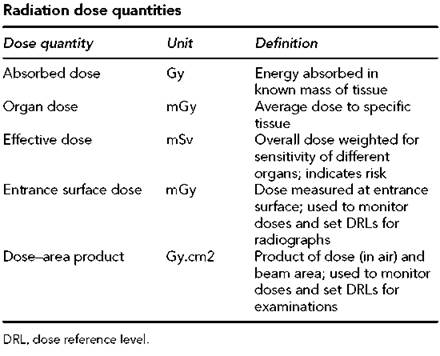
The likelihood and severity of harm depends on the amount of X-ray energy absorbed in the patient. Radiation dose (expressed in joules/kilogram (J/kg) or Gray (Gy)) is used to quantify the amount of energy absorbed within a known mass of tissue. Some types of radiation cause more harm than others for the same absorbed dose. The equivalent dose (expressed in Sieverts (Sv)) is found by multiplying the absorbed dose by the quality factor assigned to specific types of radiation. For diagnostic X-rays, the quality factor is one, so that absorbed dose and equivalent dose have the same value. The risk also depends on which organs and tissues are irradiated. To take account of this, the tissues are given a weighting factor according to their susceptibility to harm from radiation. Organ dose multiplied by the tissue-weighting factor gives the weighted equivalent dose for that organ. The effective dose for an examination (expressed in Sv) is found by adding up the weighted equivalent doses for tissues or organs that have been irradiated. Effective dose indicates the detriment to health of an X-ray, allowing for the site of the examination and the exposure conditions.
For most tissues, it is not feasible to measure organ doses directly. However, they can be derived using mathematical models of the dose distributions within simulated patients, for different examinations and exposure conditions. The models are used to convert patient dose-area product readings (expressed in Gy.cm2) or entrance skin dose measurements (expressed in mGy) into organ doses. Combining the weighted organ doses gives the effective dose for the given examination conditions. Skin doses are usually measured using thermoluminescent dosimeters (TLDs) or are calculated indirectly from tube output and back-scatter data.
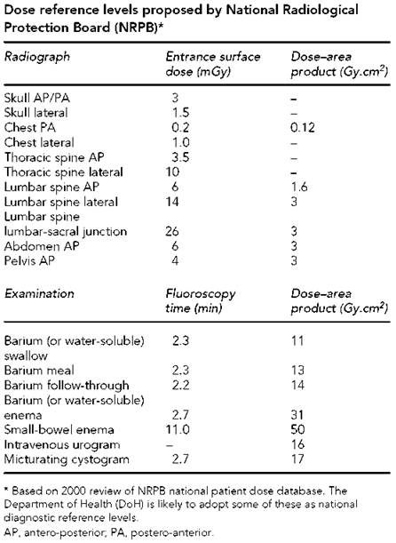
For monitoring the relative patient dose levels for different types of examination performed using a variety of equipment, it is usually sufficient to analyse dose-area product readings or skin dose data without deriving effective doses. National and local diagnostic reference levels (DRLs) will also be set in terms of these quantities. Some proposed values are shown in the table here.
Radiation risks
Radiation can cause several forms of harm. The doses for radiographic examinations are substantially lower than the threshold needed to cause immediate harmful effects due to cell-killing, such as radiation sickness. Other threshold or deterministic effects such as skin burns or damage to the lens of the eye occur only after prolonged or repeated X-ray exposures giving doses in excess of 1-2 Gy. Occasionally, skin damage has been seen after complex interventional investigations. For these procedures, it is necessary to manage this type of risk. Irradiation of a fetus during organogenesis could also lead to deterministic effects such as malformations and mental retardation when doses exceed 100-200 mGy.
Radiation risks
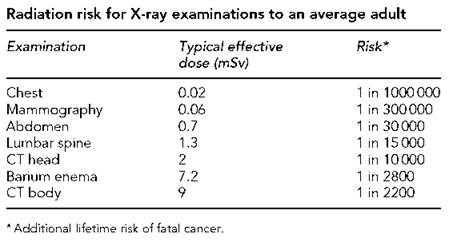
However, even low X-ray doses can cause changes to cell DNA, resulting in a slight increase in the probability of cancer occurring in the years following exposure. The additional risk of a fatal cancer ranges from less than one in 1 000 000 for chest, extremity and dental examinations to typically one in 30 000 for abdominal radiographs and more than one in 10 000 for abdominal computed tomography (CT) and barium examinations. Typically, risks for children are two or three times greater than those for average adults, while risks for elderly people are five times lower than those for average adults. Radiation protection measures reduce this stochastic risk to patients by minimizing the X-ray dose used to obtain diagnostic information.
In addition to the risk of causing somatic harm to the patient, there is also the possibility of causing genetic harm to future offspring. Irradiating the gonads of patients could potentially harm their children through the risk of heritable disease. The risk is small compared with the natural risks, but using techniques and protective measures to minimize gonad doses is a sensible and simple precaution.
Medical exposure legislation
The basic measures for the radiation protection of people undergoing medical exposures were contained in the 1990 Recommendations of the International Commission on Radiological Protection. In 1997, the European Council set out these measures in the Medical Exposure Directive (Council Directive 97/43/ Euratom) for adoption by member states. Great Britain implemented most of the provisions in the directive in the Ionising Radiations (Medical Exposure) Regulations (IRMER) 2000.
IRMER provides a comprehensive framework for protecting patients and others undergoing medical exposures and keeping their doses as low as reasonably practicable (ALARP). The requirements of IRMER follow the fundamental principles for radiation protection: all medical exposures must be justified before they take place. Possible alternatives must be considered and the benefits weighed against possible harm. Once an exposure is justified, then the equipment and protocols used for the examination must be optimized to keep doses ALARP.
Patient dose information is recorded to enable periodic dose auditing against established diagnostic reference levels.
IRMER addresses all stages of the examination process, from initial referral to evaluation of the images produced. All members of staff involved in medical exposures have clear responsibilities for protecting patients. The duty holders are the referrer, the practitioner who justifies the examination and the operators who carry out practical aspects of the examination from identification of the patient to using equipment to make the exposures.
Responsibility for implementing IRMER falls on employers. They must put in place written procedures that clearly identify the duty holders, and set out their responsibilities and the steps they must follow to ensure that the patients are properly protected through the various stages of the examination. Implementation includes the need to use written protocols, which should define standard imaging projections for a specific medical condition for each anatomical area, e.g. skull and exposure charts, to improve the consistency of standard techniques.
Procedures must also focus on issues that need special consideration by duty holders because the potential risks may be greater or the benefits less clear. These include the exposure of children, high-dose examinations, exposure of women who may be pregnant, and exposure for medical research or medicolegal purposes.
Employers must ensure that the duty holders are adequately trained to perform their duties and to meet their responsibilities to protect patients. For example, an operator carrying out a medical exposure needs to know how to optimize all aspects of that exposure in order to obtain the necessary information with the lowest practicable dose. In this case, qualified radiographers are the appropriate operators because they have the adequate training to perform these duties. To maintain their competency, practitioners and operators are required to keep up to date with the latest developments in patient protection and improved techniques through continuing education.
Example list of Ionising Radiation (Medical Exposure) Regulations (IRMER) employers' procedures for X-ray examinations
Patient identification
Identification of referrers, practitioners and operators
Medical exposure justification
Females of childbearing age
Examination evaluation and dose recording
Patient dose assessment
Use of diagnostic reference levels
Quality assurance of IRMER operation
Medicolegal exposures
Exposures for medical research
Reducing unintended doses
Investigation of unintended exposures

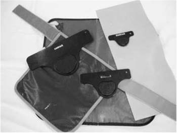
Typical gonad shields with sheet of lead rubber for gonad protection

Examples of immobilization devices
Practical protection measures
It is the duty of the operators carrying out medical exposures to take practical steps to protect the patient. These may involve:
• patient preparation;
• patient identification;
• special patient issues, e.g. paediatrics, females;
• selection of imaging equipment;
• type of image receptor;
• patient positioning;
• exposure technique;
• image projection;
• beam collimation;
• exposure parameters;
• patient protective equipment and shielding.
Protection of the patient from any unnecessary primary and scatter radiation should be employed. The gonads should not be in the line of the primary beam for projections other than the abdomen, and therefore careful radiographic technique is essential, e.g. radiography of the hand (see p. 5).
Special care must be taken to collimate the beam to the area of interest, thus avoiding the unnecessary irradiation of tissue and reducing scatter radiation. When more radiation-sensitive tissues are located in the image-acquisition field, these should be excluded whenever possible, e.g. the use of gonad shields and the modification of projections to reduce irradiation of the lens of the eye or the thyroid gland.
Protection from scattered radiation is employed by the intelligent use of lead protective materials protecting the gonads and should be employed regularly in extremity radiography.
In order to reduce repeat images, the use of foam pads, sandbags and other immobilizing devices should be used to ensure that the patient is immobilized and in a position that is as comfortable as possible. The shortest exposure time should be selected to avoid movement unsharpness.
The fastest imaging system (film/screen combination or fastest CR phosphor plates) should be selected appropriate to the diagnostic information required, thus ensuring that the dose is ALARP.
Pregnancy rule
To avoid irradiating a fetus, a ‘pregnancy rule’ should be observed carefully. IRMER requires employers to have a written procedure for this. If a woman of childbearing age is, or cannot be certain that she is not, pregnant, then direct irradiation of the abdomen and pelvis should be avoided. The only exception to this rule is when those justifying the procedure in conjunction with the referring clinician can state that there are overriding clinical reasons for the requested examination to proceed. In such cases, all steps must be taken to minimize the number of exposures and the absorbed dose per exposure. Examinations of regions other than the abdomen and pelvis may proceed, provided there is good beam collimation and lead protection of the abdomen and pelvis.