Introduction
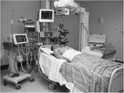
Ward radiography should be restricted to the patient whose medical condition is such that it is impossible for them to be moved to the X-ray department without seriously affecting their medical treatment and nursing care. Such patients may be found in surgical and medical ward environments and in the following areas:
• coronary care unit;
• medical assessment unit;
• surgical assessment unit;
• cardiac surgery unit;
• intensive care unit (ICU);
• high dependency unit;
• special care baby unit;
• orthopaedic ward;
• accident and emergency ward.
General comments
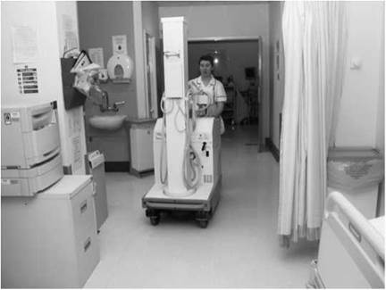
Examinations are normally complicated by a variety of situations: the patient's medical condition; degree of consciousness and cooperation; the patient's treatment; restrictions due to life- support system, drips, and chest or abdominal drains; location of electrocardiogram (ECG) leads; traction apparatus; physical restrictions due to room size and layout of monitoring and life- support equipment; adequate power supply; and the shape, size and ability to move mobile or portable X-ray equipment in confined spaces.
The radiographer must be able to assume total control of the situation, and should enlist the help, cooperation and advice of nursing and medical staff before embarking on an examination.
Any X-ray requests should be checked first to ensure that the examination on the ward is necessary, and that the correct equipment and cassettes are obtained for transfer to the wards.
The patient should be correctly identified and cassettes used clearly marked to avoid double exposure if more than one patient needs examining on the ward.
A thorough examination of the location of, or knowledge of, the ward is necessary in order that any problems or difficulties can be resolved with the minimum of fuss.
Advice regarding the patient's medical condition should be sought first, before moving or disturbing the patient. Any disturbance of traction, ECG leads or drains should be undertaken only with the permission of the medical staff. Positioning of cassettes and movement or lifting of seriously ill patients should be undertaken with supervision from nursing staff.
Radiation protection
• This is of paramount importance in the ward situation. The radiographer is responsible for ensuring that nobody enters the controlled area during exposure of the patient.
• The radiographer must liaise clearly with the ward staff on their arrival on the ward and issue verbal instructions in a clear and distinct manner to staff and patients to avoid accidental exposure to radiation.
• The radiographer, and anyone assisting in an examination, must be protected adequately from scatter radiation by the use of a lead-rubber apron.
• Use of the inverse square law, with staff standing as far away as possible from the unit and outside the radiation field, should be made when making an exposure. The patient should also receive appropriate radiation protection.
• Lead protective shields may be used as backstops when using a horizontal beam to limit the radiation field, e.g. when the absorption nature of room-dividing walls is unknown.
• Exposure factors used for the examination should be recorded, enabling optimum results to be repeated. Patients tend to be X-rayed frequently when under intensive care.
Control of infection
The control of infection plays an important role in the management of all patients, especially following surgery and in the nursing of premature babies.
To prevent the spread of infection, local established protocols should be adhered to by staff coming into contact with patients, e.g. hand-washing between patients and the cleanliness of equipment used for radiographic examination.
Patients with a known highly contagious infection, and those with a compromised immune system and at high risk of infection, will be barrier-nursed. In such circumstances, it is important that local protocols associated with the prevention of spread of infection are followed.
The X-ray equipment used in ICU, cardiac surgery units and special care baby units should, ideally, be dedicated units and kept on site. Failing this, they should be cleaned with antiseptic solution before being moved into infection-controlled units. Equipment is wheeled over dust-absorbent mats at the entrance of such units. Radiographers should wear gowns or disposable plastic aprons, facemasks and over-shoes before entering these areas. Cassettes should be cleaned and covered with plastic sheets or clean pillowcases/towels before use. After use, cassettes and all equipment should be cleaned with antiseptic solution. Disposable gloves are worn when touching the patient.
Methicillin-resistant Staphylococcus aureus (MRSA) is a bacterial infection that is resistant to methicillin and many other antibiotics. MRSA is a particular threat to vulnerable patients and can cause many symptoms, including fever, wound and skin infections, inflammation and pneumonia. The bacteria can be spread readily from an infected patient to others. MRSA is spread mainly from person to person by hand. When healthcare workers deal with MRSA-infected patients, the bacteria may transfer to their hands and can then be passed on to a vulnerable patient.
MRSA patients are usually barrier-nursed. Controls such as effective hand-washing, wearing of gloves and aprons, and the cleaning of the environment and equipment are necessary to prevent spread of the bacteria.
When undertaking radiography on more than one barrier- nursed patient on a ward or ICU, it is important that disposable aprons are changed between patients as well as ensuring that the hands of the operators are washed between patients to prevent the spread of infection. A number of speciality wards use differently coloured aprons per patient bay as a prompt to confine the use of aprons to a specific patient.
Accessory equipment
• Various aids are available that can assist in positioning both the patient and cassette. These include foam pads of different sizes and shapes, such as cassette pads that support the patient and allow the cassette to be inserted in a groove in the pad, cassette tunnels and cassette holders. The correct accessories should be selected as part of the equipment needed for the radiographic procedure.
• Selection of a low-ratio 6:1 30 lines per cm parallel stationary grid will reduce the risk of grid cut-off when undertaking conventional radiography.
X-ray equipment
Units fall broadly into two groups - portable and mobile, the broad distinction between the two being the difference in power output and the ability to transfer equipment.
• Portable sets have relatively low mA settings and normally can be dismantled for transfer. Mobile sets have higher power output, are much heavier, and need to be motorized or pushed between locations.
• Mobile X-ray units can be either mains-independent or mains-dependent. These types of machines are very heavy and may be battery-driven to aid transportation around the hospital.
• Older mobile sets, with conventionally powered X-ray generators, require the need of a separate 30-A supply and are connected to socket outlets marked 'X-ray only'. Patients requiring radiography with such machines should be nursed in beds that are within reach of these sockets.
• Capacitor discharge (CD) units require the use of a 13-A supply to generator X-ray exposure. Their use in special care baby units or similar high dependency units is not recommended because of the risk of disconnection of the wrong electrical plug when many electrical devices are employed.
• Mains-independent machines such as medium-/high-frequency can be operated from a standard 13-A supply. These are designed with high-powered battery packs to generate the electrical power for X-ray exposure. Therefore, these units can be moved to areas without electrical mains power or in wards where there is a restriction of mains sockets. They require only access to a 13-A power supply for battery recharging during storage.
• In radiography of the chest and abdomen, the use of short exposure times is essential to reduce the risk of movement unsharpness. For such examinations, the choice of equipment is therefore restricted to the higher-output mobile sets.

Heart and lungs
Patients suffering from dyspnoea and severe chest pain are often assessed on the ward. Radiographs are requested to aid in diagnosis. Common conditions include congestive heart failure, coronary heart disease, left ventricular failure, pulmonary oedema, pulmonary embolus, pneumothorax and pleural effusion and pneumonia. Postoperative chest radiography is also often required.
As a general rule, ward radiography should be performed only when it is not possible to move the patient to the X-ray department and when medical intervention is dependent on the diagnosis confirmed on the radiograph.
Antero-posterior
Position of patient and cassette
• Where possible, the patient should be X-rayed sitting erect and facing the X-ray tube. The cassette is supported against the back, using pillows or a large wedge-shaped foam pad, with its upper edge above the lung fields.
• If this is not possible, the patient may be positioned supine. The semi-recumbent position is not favoured as the degree of recumbence is not reproducible across a series of images.
• The median sagittal plane is adjusted at right-angles to, and in the midline of, the cassette.
• Rotation of the patient is prevented by the use of foam pads. Rotation produces a range of artefacts (see p. 205) and must be avoided or minimized. If possible, the arms are rotated medially, with the shoulders brought forward to bring the scapulae clear of the lung fields.
Direction and centring of the X-ray beam
• Assuming the patient can sit fully erect, the central ray is directed first at right-angles to the cassette and towards the sternal angle.
• The central ray is then angled until it is coincident with the middle of the film, thus avoiding unnecessary exposure to the eyes.
• The use of a horizontal central ray, however, is essential to demonstrate fluid, e.g. pleural effusion or any air under the diaphragm. If the patient is able to sit erect, direct the central ray at right-angles to the middle of the cassette. The clavicles in the resultant radiograph, however, will be projected above the apices.
• If the patient is unable to sit erect, fluid levels are demonstrated using a horizontal ray with the patient lying down in the positions (described on p. 355 opposite).
Notes
• Where possible, a high-powered mobile is used to enable a 180-cm focus-to-film distance (FFD) for erect positioning of the patient.
• For supine images, the FFD may be restricted due to the height of the bed and the height limitations of the X-ray tube column. The FFD should be higher than 120 cm, otherwise image magnification will increase disproportionately.
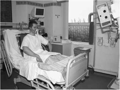
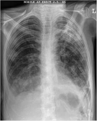
Antero-posterior erect radiograph showing bilateral consolidation with a right pleural effusion (in this case due to tuberculosis)
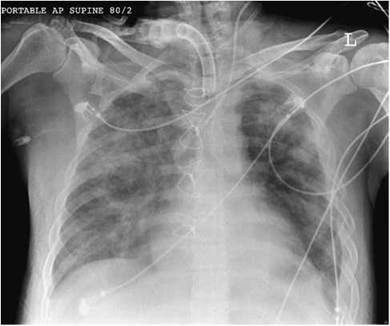
Antero-posterior supine radiograph showing extensive pulmonary oedema and haemorrhage after trauma, with multiple left-sided rib fractures. Sternal wires indicate previous cardiac surgery. Note left jugular central line and tracheostomy. It is not possible to exclude pleural effusion or pneumothorax on an antero-posterior supine image
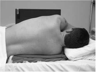
Patient positioned for postero-anterior chest (lateral decubitus) projection

Postero-anterior radiograph in lateral decubitus position showing pleural effusion with pneumothorax
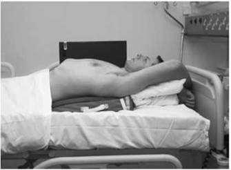
Patient positioned for lateral chest (dorsal decubitus) projection
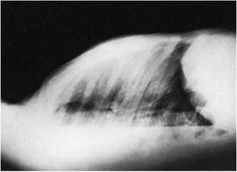
Lateral radiograph in dorsal decubitus position showing pleural effusion with pneumothorax
Patients who are too ill to sit erect may be examined whilst lying down. The use of a horizontal central ray is essential to demonstrate fluid levels, e.g. hydropneumothorax.
Postero-anterior or antero-posterior
(lateral decubitus)
This projection is used to confirm the presence of fluid. Moving the patient into a different position causes movement of free fluid, so that loculation is also detected. It may also be used to demonstrate the lateral chest wall of the affected side clear of fluid, and to unmask any underlying lung pathology.
Position of patient and cassette
• The patient is turned on to the unaffected side and, if possible, raised on to a supporting foam pad.
• A cassette is supported vertically against the anterior chest wall, and the median sagittal plane is adjusted at right-angles to the cassette.
• The patient's arms are raised and folded over the head to clear the chest wall.
Direction and centring of the X-ray beam
• Centre to the level of the eighth thoracic vertebra, with the central ray horizontal and directed at right-angles to the cassette.
Alternatively, an antero-posterior projection may be taken, with the cassette supported against the posterior aspect of the patient.
Lateral (dorsal decubitus)
This projection will show as much as possible of the lung fields,
clear of a fluid level, when the patient is unable to turn on their side.
Position of patient and cassette
• The patient lies supine and, if possible, is raised off the bed on a supporting foam pad.
• The arms are extended and supported above the head.
• A cassette is supported vertically against the lateral aspect of the chest of the affected side and adjusted parallel to the median sagittal plane.
Direction and centring of the X-ray beam
• Centre to the axilla, with the central ray horizontal and directed at right-angles to the cassette.
Notes
• Further projections may be taken with the patient lying on the affected side or in the prone position to disclose further aspects of the lung fields not obscured by fluid.
• A grid cassette may have to be used if the width of the thorax is likely to produce an unacceptable amount of secondary radiation.
Patients suffering from heart block are often treated with an electrical pacemaker, which regulates the heart rate. A temporary cardiac electrode is used consisting of a bipolar wire 100-cm long, covered in Teflon, and terminating in a platinum tip electrode separated from a second electrode, which encircles the wire. At the other end, two wires are connected to a battery pacemaker.
The electrode is usually passed into the right subclavian vein and directed into the right ventricle, where the tip is lodged against the endocardial surface near the lower part of the interventricular septum. An electrical impulse is generated across the endocardial surface and adjusted to the required heart rate.
This procedure may be performed in a cardiac catheter laboratory, if available, or in a side ward or dedicated pacing room adjacent to a coronary care facility.
The procedure described below, using a mobile image intensifier, is typical of an insertion of a temporary pacemaker in a side ward dedicated for this procedure.

Radiographer positioning the image intensifier prior to pacemaker wire insertion via the left subclavian vein approach
Mobile image intensifier
• A mobile image intensifier (23 or 31 cm) is selected. As insertion of the electrodes may be prolonged, it is important that the set is equipped with 'last image hold' and pulsed fluoroscopy in order to reduce patient and staff dose.
• The patient lies on a trolley or bed with a radiolucent top, which can accommodate the C-arm of the intensifier.
• The intensifier is positioned on the opposite side of the operating position, with the long axis of the machine at right- angles to the bed or trolley and with the intensifier face above and parallel to the patient's upper thorax.
• The wheels of the image intensifier are rotated in order to allow free longitudinal movement of the device, with the cross-arm brakes released to facilitate movement across the patient.
• During the procedure, the image intensifier is 'panned' so that the advancement and direction of the tip are observed until the tip of the electrode is located correctly within the right ventricle.
• Control of the screening factors, screening time and radiation protection is the responsibility of the radiographer.
• As the procedure is performed under aseptic conditions, a sterile protective cover is normally secured to the image intensifier housing.
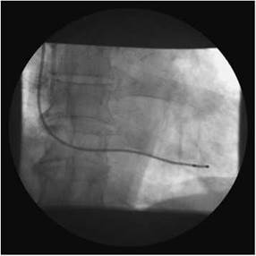
Fluoroscopic image showing location of pacemaker wire

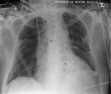
Antero-posterior supine radiograph showing bilateral basal chest drains, endotracheal tube, right jugular central venous catheter and a pulmonary artery catheter (in this case unusually passing to the left pulmonary artery rather than the right). Note: to avoid confusion the extracorporeal part of the pulmonary artery catheter (arrowheads) should have been positioned out of the field of view

Erect antero-posterior radiograph of chest showing intercostal drain in situ for pneumothorax
Patients who have undergone major cardiac or thoracic surgery are invariably nursed intensively in either a cardiac surgery unit or ICU, depending on the type of surgery performed. Such patients can be connected to an assortment of catheters and tubes for monitoring purposes and chest drainage, e.g. following post-cardiac or -thoracic surgery for drainage of the thoracic cavity of fluid and connections to underwater seals may be necessary to keep the lungs inflated. Strict control of infection procedures must be followed to ensure that the patient is not exposed to infection. A series of radiographs may be required during postoperative care, the first shortly after surgery. The first radiograph, and for a few days until the patient is fit to sit erect, is usually taken with the patient supine. The same principles of consistent radiographic positioning and exposure are applied to enable accurate comparisons of radiographs over a period of time. The positioning of the patient should be carried out using a rehearsed lifting procedure to reduce patient movement and undue back strain for everyone involved in handling the patient. Care should also be taken to expose on full inspiration when the patient is connected to a ventilator.
Endotracheal tube
The position of an endotracheal tube can be assessed from an antero-posterior projection of the chest, which must be exposed with enough penetration to show the trachea and carina. The position of the tube is checked to ensure that its distal end is not lying in the right bronchus.
Central venous pressure line
A fine catheter is positioned in the superior vena cava in seriously ill patients as a means of measuring central venous pressure and injecting drugs. The catheter may be introduced via one of the jugular or subclavian veins, or a peripheral vein. The position of a catheter or line can be assessed from the antero-posterior projection of the chest exposed with enough kilovoltage to penetrate the mediastinum. The position of the catheter is checked to ensure that its distal end has not been directed into the right internal jugular vein or the right atrium of the heart. The root of the neck should be included on the radiograph. There is a risk of inducing a pneumothorax with this procedure and therefore it is important that the chest image includes the apex of the lung.
Chest drain insertions
Chest drains are used for drainage of pneumothorax or pleural effusion, either spontaneous or following cardiac or thoracic surgery. If the drain is connected to an underwater seal chamber, care must be taken not to elevate the chamber above the level of the drain, or water may siphon back into the thorax. An antero-posterior erect image is required to show the position of the tube and to show any residual air within the thorax.
Abdomen
Mobile radiography is often required in cases of acute abdominal pain or following surgery, when the patient is unstable, to determine whether any of the following are present:
• gaseous distension of any part of the gastrointestinal tract;
• free gas or fluid in the peritoneal cavity;
• fluid levels in the intestines;
• localization of radio-opaque foreign bodies;
• evidence of aortic aneurysm.
Recommended projections
Typical imaging protocols are described in Section 11. Below is a summary of some of projections used for the conditions listed.
|
Gaseous distension |
Antero-posterior abdomen, patient supine |
|
Free gas in the peritoneal cavity |
Antero-posterior chest, patient erect Antero-posterior abdomen, patient supine Antero-posterior/postero- anterior left lateral decubitus |
|
Fluid levels |
Antero-posterior abdomen, patient erect |
|
Radio-opaque foreign bodies |
Antero-posterior abdomen, patient supine |
|
Aortic aneurysm |
Antero-posterior abdomen, patient supine Lateral (dorsal decubitus) |
Antero-posterior - supine
Position of patient and cassette
• With the patient supine, a grid cassette is carefully positioned under the abdomen. The patient may be lifted by using a well- rehearsed and safe lifting technique whilst a cassette is slipped beneath them. Care should be exercised to avoid hurting the patient by forcing a cassette into position, or using a cold cassette, which might shock the patient.
• The grid cassette should be positioned to include the symphysis pubis on the lower edge of the image. The cassette should also be in a horizontal position on the bed and not lying at an angle. If the cassette is not flat, there may be grid cut-off of the radiation beam, which may give the appearance of a lesion of increased radio-opacity, such as an intra-abdominal mass due to loss of image density.
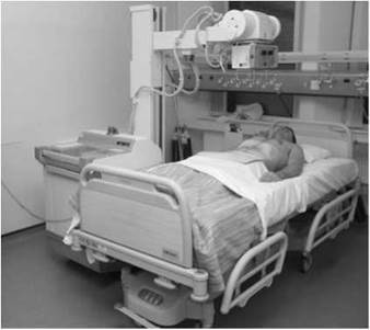
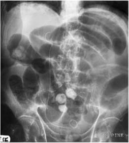
Supine portable radiograph of abdomen showing small bowel obstruction. Also note the right ureteric pigtail stent as patient had transitional cell carcinoma of the bladder
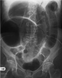
Supine portable radiograph of abdomen showing distal colonic obstruction
Direction and centring of the X-ray beam
• Direct the central ray at right-angles to the cassette and in the midline at the level of the iliac crests.
• Exposure is made on arrested expiration.
Notes
• Radiographs may be taken using a high kVp technique to shorten the exposure time and reduce movement blur, although the increased scatter may degrade the contrast and reduce the ability to see the organ outlines.
• Foam pads may be used to prevent rotation of the patient.


Antero-posterior erect radiograph of abdomen showing small bowel obstruction, with gas in the bowel wall (right upper quadrant) indicating impending perforation

Antero-posterior left lateral decubitus image of the abdomen showing free air in the abdominal cavity

Antero-posterior - erect
The mobile set is positioned to enable horizontal beam radiography necessary for the demonstration of fluid levels.
Position of patient and cassette
• Depending on the patient's medical condition, the patient's bed is adjusted to enable the patient to adopt an erect or semi-erect position. If necessary, a number of pillows or an alternative supporting device are positioned behind the patient to aid stability.
• The patient's thighs are moved out of the beam to ensure that they are not superimposed on the image.
• A 35 X 43-cm grid cassette is placed against the posterior aspect of the patient, with the upper border of the cassette positioned 2 or 3 cm above the xiphisternal joint to ensure that the diaphragm is included on the image to enable demonstration of free air in the peritoneal cavity.
Direction and centring of the X-ray beam
• The horizontal central ray is directed to the centre of the cassette using a 100 cm FFD with care taken to avoid grid cut-off.
Antero-posterior (left lateral decubitus)
This projection, which uses a horizontal central ray, is selected as an alternative to the antero-posterior erect projection when the patient is unable to sit. It is also useful in demonstrating free air in the peritoneal cavity.
Position of patient and cassette
• The patient is turned on to the left side, ideally for 20 minutes, allowing any free air in the abdominal cavity to rise toward the right flank to avoid the problem of differential diagnosis when air is present on the left side of the abdomen within the region of the stomach.
• The grid cassette is supported vertically at right angles to the horizontal central ray, and is positioned against the posterior aspect of the patient to include the right side of the diaphragm.
Direction and centring of the X-ray beam
• The horizontal central ray is directed to the centre of the cassette using a 35 X 43-cm grid cassette.
Lateral dorsal decubitus - supine
This projection is selected as an alternative to the antero-posterior projection, with the patient in the left lateral decubitus position, when the patient is too ill to move. It is also used to demonstrate calcification of the abdominal aorta. Abdominal aortic calcification is variable, even in the presence of an aneurysm, and in modern practice it would be more usual to perform ultrasound to assess the size of the aorta and the possibility of abdominal aneurysm. Ultrasound can be done in the emergency room. Computed tomography (CT) scanning offers a greater possibility of demonstrating leak from an aneurysm if the patient is sufficiently stable.
Position of patient and cassette
• The mobile set is positioned so as to enable horizontal beam radiography.
• The patient lies supine and, if possible, is raised off the bed on to a supporting foam pad.
• The arms are extended and supported above the head.
• A grid cassette is supported vertically against the lateral aspect of the abdomen and adjusted parallel to the median sagittal plane.
• The image should include the dome of the diaphragm, the anterior abdominal wall and the vertebral bodies.
Direction and centring of the X-ray beam
• The horizontal central ray is directed to the centre of the cassette.
Radiation protection
• A mobile radiation protection barrier should be positioned behind the cassette to confine the primary radiation field.
Note
Free air in the peritoneal cavity can sometimes be demonstrated on a conventional antero-posterior radiograph. In the example opposite, free gas is demonstrated by the presence of a double wall sign. In this image both inside and outside of the bowel wall are seen, as compared with just the lumen side normally, as the result of air both within the lumen of bowel and free in the peritoneal cavity surrounding the section of bowel.
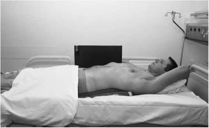
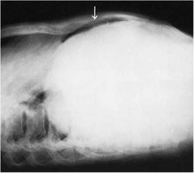
Lateral dorsal decubitus image of the abdomen showing free air in the peritoneal cavity lying adjacent to the anterior abdominal wall

Antero-posterior radiograph of abdomen showing extensive free air in the peritoneal cavity (arrowheads) and double lumen effect demonstrated in left upper abdomen (arrows)
30 days on traction
Cervical spine
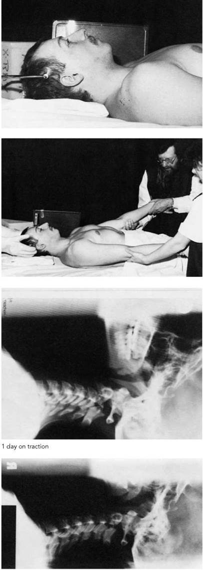
A patient with a spinal fracture dislocation is commonly nursed with skull traction and weights. This is applied by means of a skull calliper secured to the outer table of the parietal regions of the skull. Necessary weights in the early stages of traction may be more than those that are required to maintain realignment of the vertebrae. Traction is continued until there is consolidation.
Lateral projections of the cervical vertebrae, over several weeks, are necessary to assess the effectiveness of the traction and demonstrate the alignment of the vertebrae in relation to the spinal cord. Each radiograph is marked with the weight of the applied traction.
Lateral supine
Position of patient and cassette
• The mobile set is positioned so as to enable horizontal beam radiography.
• With the patient in the supine position, a 24 X 30 or 18 X 24-cm cassette is supported vertically against either shoulder, parallel to the cervical vertebrae and centred at the level of the prominence of the thyroid cartilage.
• The cassette is secured in position using a holder or sandbags.
• The patient's shoulders must be depressed by the supervising doctor gripping the patient's wrists and pulling the arms caudally.
Direction and centring of the X-ray beam
• The horizontal central ray is directed to a point vertically below the prominence of the thyroid cartilage at the level of the mastoid process through the fourth cervical vertebra.
Note
In the radiographs opposite, part of the skull has been included on the film to show where the skull calliper is secured to the parietal regions.
Radiation protection
• A mobile radiation protection barrier should be positioned behind the cassette to confine the primary radiation field.
• The person applying the traction must be medically supervised and wear a radiation protective lead-rubber apron and lead-rubber gloves.
Fractured lower limbs and pelvis
Orthopaedic radiography may be required to be undertaken on the ward immediately following surgery or following the application of traction. For the limbs, two radiographs are taken at right- angles to each other to check on the position and alignment of fractured bones. Examination of the patient will be made difficult if a suspension system is used, which will include weights and a metal pulley rope structure that is connected to the patient's bed. Great care should be exercised not to disturb these appliances, as they may disturb the position of the fractured bones and add to the patient's pain. A heavy patient may tend to sag into the mattress of the bed, which complicates matters when positioning for projections of the upper femur. The patient may be able to lift their bottom off the bed using the overhead hand grip so that a support pad or cassette tunnel device can be introduced under the buttocks.
Antero-posterior
Position of patient and cassette
• The mobile set is positioned carefully relative to any overhead bed supports, with adjustment being made with support of the nursing staff.
• A suitably sized cassette is selected and carefully positioned under the femur or lower leg to include the joint nearest the fracture and as much of the upper or lower limb as possible to enable bone alignment to be assessed.
• The cassette is supported parallel to the femur or lower limb by the use of non-opaque pads.
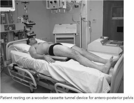
• For fractures of the neck of femur or pelvis, a cassette tunnel device may be used, which needs only one major disturbance to the patient. Once in position, a cassette may be positioned without any further disruption to the patient. This also serves in aiding the positioning for the lateral projection when the patient is raised, allowing adequate demonstration of the femur.
Direction and centring of the X-ray beam
• Direct the central ray at right-angles to the middle of the cassette with the central ray at right angles to the long axis of the bones in question, in accordance with the techniques previously described in the chapter on the lower limb.
Note
Repeat examinations will be required over a period of time to assess the effectiveness of treatment; therefore, careful positioning and exposure selection are required to ensure that images are comparable.
Radiation protection
• Radiation protection is particularly important, and gonad shields should be used.
• A mobile radiation protection barrier should be positioned behind the cassette to confine the primary radiation field when undertaking lateral projections.

Fractured femur
Lateral
Position of patient and cassette
• The mobile X-ray equipment is carefully repositioned to enable horizontal beam radiography.
• When the examination is for the distal two-thirds of the femur, the cassette may be positioned vertically against the medial side of the thigh and the horizontal beam directed latero-medially.
• When the proximal part of the shaft or the neck of the femur is being examined, the cassette is positioned vertically against the lateral side of the thigh and the beam is directed mediolaterally, with the opposite leg raised on a suitable support so that the unaffected thigh is in a near-vertical position.
• For the neck of femur, a grid cassette is positioned vertically, with one edge against the waist above the iliac crest on the side being examined and adjusted with its long axis parallel to the neck of femur.
• To demonstrate fractures of the upper femur, it is essential that the patient is raised off the bed on a suitable rigid structure, such as a firm foam pad or a cassette tunnel device.
Direction and centring of the X-ray beam
• For the distal two-thirds of the femur, the horizontal central ray is centred to the middle of the cassette and parallel to a line joining the anterior borders of the femoral condyles.
• To demonstrate the neck of femur, which will include the hip joint, centre midway between the femoral pulse and the palpable prominence of the greater trochanter, with the central ray directed horizontally and at right-angles to the cassette.
Note
When using a grid, it is essential that the cassette remains vertical to avoid grid cut-off.
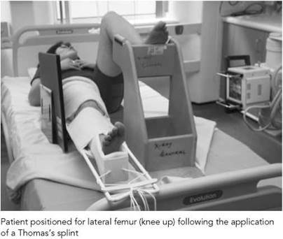

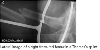

Arthroplasty postoperative
radiography
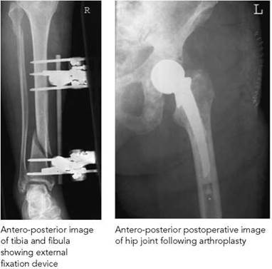
An antero-posterior projection of the hip is taken within 24 hours of surgery to include the upper third of the femur to demonstrate the prosthesis and the cement restrictor, which is distal to the prosthesis. This may be highlighted by a radio-opaque marker in the form of a ball-bearing, which should appear in all subsequent follow-up images of the hip joint if it has been used.
Loosening of the prosthesis can occur by impaction of the femoral shaft of the prosthesis into the native femur. This is detected most easily by observing a reduction in the distance between the cement restrictor and the tip of the prosthesis. It is therefore most important that the first image includes the cement restrictor.
The nursing management is also determined on confirmation that the hip joint has not dislocated.
Antero-posterior and lateral projections are acquired of the knee joint following knee joint replacement.
This type of traction is used on children from birth to 12 months. Two projections, antero-posterior and lateral, are taken to assess bone alignment and new bone formation. The application of gonad protection and careful collimation of the X-ray beam are essential. Great care should be exercised to avoid disturbing the traction; however, it is still usually possible to maintain traction and rotate the child so that the front of the suspended legs are facing the side of the cot, which can be lowered during exposure to avoid superimposition of the cot’s vertical bars.
Antero-posterior
Position of patient and cassette
• With the child lying supine, with both legs suspended vertically, a cassette is supported against the posterior aspect of the affected leg using foam pads or an L-shaped plastic cassette support device.
• The cassette is positioned to enable full coverage of the femur, including the knee and hip joints.
Direction and centring of the X-ray beam
• Centre to the middle of the anterior aspect of the femur, with the horizontal central ray at right-angles to the cassette.
Lateral
Position of patient and cassette
• To avoid superimposition of the unaffected femur, the sound limb is carefully removed from the traction by the medical officer and held in a position outside the radiation beam.
• Alternatively, the traction may be adjusted and the sound limb supported temporarily in a different position.
• The medical officer or health professional must wear a lead- rubber apron and lead-rubber gloves.
• A cassette is supported vertically against the lateral aspect of the affected leg and adjusted parallel to the femur.
Direction and centring of the X-ray beam
• Centre to the middle of the medial aspect of the femur, with the horizontal central ray at right-angles to the cassette.
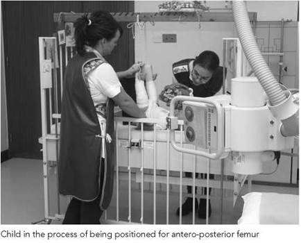

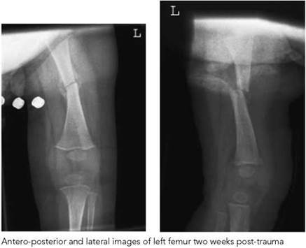
Heart and lungs - special care baby unit
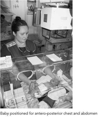
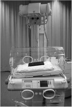
Neonates suffering from respiratory distress syndrome are examined soon after birth to demonstrate the lungs, which are immature and unable to perform normal respiration. The baby will be nursed in an incubator and may be attached to a ventilator. The primary beam is directed through the incubator top, with care being taken to avoid any opacity or cut-outs in the incubator top falling within the radiation beam.
Many designs of incubators are available, with many requiring the cassette to be placed within the incubator. However, a number are designed to facilitate positioning of the cassette on a special tray immediately below and outside the incubator housing.
A full account of neonatal radiography is given in Section 14.
Antero-posterior
• An 18 X 24-cm cassette that is at body temperature is selected. Disposable sheets should be used between the baby and the cassette.
Position of patient and cassette
• The baby is positioned supine on the cassette, with the median sagittal plane adjusted perpendicular to the middle of the cassette, ensuring that the head and chest are straight and the shoulders and hips are level. When using the cassette tray the incubator head end is raised five to ten degrees to avoid a 'lordotic' chest or alternatively a wedge pad is used to raise the shoulders.
• The head may need holding with the chin raised up to avoid the chin obscuring the lung apices, or supported using small covered sandbags. Arms should be on either side, slightly separated from the trunk to avoid being included in the radiation field and to avoid skin crease artefacts, which can mimic pneumothoraces. The arms can be immobilized with Velcro bands and/or sandbags.
Direction and centring of the X-ray beam
• No single centring point is advised.
• Centre the beam to the correct size of the chest.
• The central ray is directed vertically, or angled five to 10 degrees caudally if the baby is completely flat, but if doing so, care should be exercised not to cause the chin to be projected over the apices.
• Constant maximum FFD should be used.
Notes
• Very short exposure times are required for these procedures. A high-frequency generator will give very low mAs and extremely short exposure in the millisecond range.
• Lead-rubber shapes should be placed on the incubator top to protect the gonads and thyroid gland.
• Exposure factor details should be recorded for subsequent imaging, and image comparisons with positioning legends should be recorded on the image.