
Introduction
Theatre radiography plays a significant role in the delivery of surgical services. The following settings are typical examples where the radiographer is required:
• non-trauma corrective orthopaedic surgery;
• trauma orthopaedic surgery;
• interventional urology;
• operative cholangiography;
• specialized hysterosalpinography procedures;
• emergency peripheral vascular procedures.
Liaison
• The radiographer must contact the theatre superintendent upon arrival and maintain a close liaison with all persons performing the operation, consequently working as part of the multidisciplinary team.
• The radiographer must be familiar with the layout and protocols associated with the theatre to which they are assigned, demonstrate a working knowledge of the duties of each person in the operating theatre, and ascertain the specific requirements of the surgeon who is operating.
Personnel preparation
• Personal preparation is the first concern of the radiographer before entering an aseptic controlled area.
• The radiographer removes their uniform (and any jewellery), and replaces them with theatre wear. The hair is covered completely with a disposable hat. Theatre shoes or boots are worn, and a facemask is put on. In addition, a film-monitoring badge is pinned to theatre garments.
• Special attention is made to washing the hands using soap, ensuring that the hands are washed before and after each patient. If the skin has an abrasion, this should be covered with a waterproof dressing.

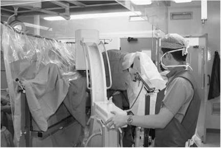
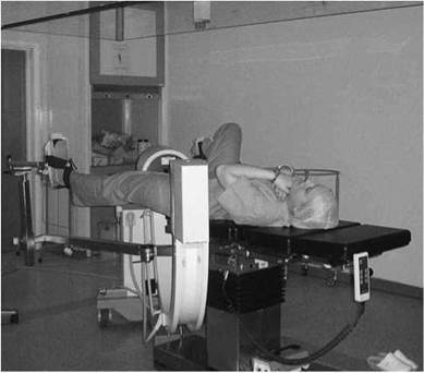
The above photographs are taken during a dynamic hip screw procedure and show the use of a sterile protective barrier as described on page 374
Equipment
• A mobile X-ray unit or mobile image intensifier is selected, depending on the requirement of the radiographic procedure. For example, a mobile X-ray unit may be used for plain-film chest radiography, while a mobile image intensifier may be used for the screening of orthopaedic procedures such as hip pinning.
• Before use, an image intensifier should be assembled and tested ahead of the procedure to ensure that it is functioning effectively prior to patient positioning.
• For the prevention of infection, the unit selected should be cleaned and dried after each patient. Where appropriate, protective plastic coverings can be used to reduce blood contamination during surgical procedures. When blood or other bodily fluids do come into contact with the imaging equipment, an appropriate cleaning solution, as advised by the local infection control officer, should be used.
• Exposure parameters are then adjusted to those required for screening or image recording on film.
Darkroom facilities/PACS connectivity
In many theatre suites, it is customary for X-ray equipment and darkroom processing facilities to be housed within the complex. Processing equipment should be switched on and tested upon arrival. Adequate levels of film processor replenisher solutions should be prepared if required and a supply of cassettes and films made available for use. With modern mobile image intensifiers a PACS DICOM link should be established to facilitate image capture and retrieval of previous images.

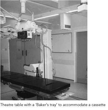
Mobile X-ray set positioned for plain image radiography using a ‘Baker’s tray’ to accommodate a cassette

Accessory equipment
• Cassette holders, stationary grids, cassette tunnels and serial changer devices should be cleaned and checked if required.
• An operating theatre table with an adjustable cassette tray should be checked for movement, and the radiographer should be familiar with the function and be able to position cassettes, when requested, with the minimum of fuss.
• Contrast media, if required, should also be supplied to the theatre staff.
Radiation protection
• Radiation protection is the responsibility of the radiographer operating the X-ray equipment. Therefore, the radiographer should ensure that film monitoring badges, lead protective aprons and thyroid shields are worn by all staff wherever possible. Furthermore, as soon as the imaging equipment is switched on, a controlled area exists. Therefore, all doors that have access to the controlled area must display radiation warning signs.
• The inverse square law principle must be applied in the theatre environment. Therefore, staff must be standing at the maximum distance from the source of radiation, and outside the path of the radiation field during exposure.
• The radiation field should be collimated to at least the size of the film or intensifier, and cassette support devices should be used to hold cassettes.
• The radiographer should use the fastest film/screen combination consistent with the examination to reduce radiation dose, or they should aim to maximize the use of dose-saving facilities whilst using an image intensifier.
• Patient identification must be confirmed with either the anaesthetist or an appropriate member of the theatre team before any radiation exposure.
• Records should be kept of patient details, exposure time and radiation dose when screening is employed.
• The radiographer must give clear instructions to staff before exposures are made regarding their role in reducing the risk of accidental exposure.
Sterile areas
The radiographer should avoid the contamination of sterile areas. Ideally, equipment should be positioned before any sterile towels are placed in position, and care should be exercised not to touch sterile areas when positioning cassettes or moving equipment during the operation.
Non-trauma corrective orthopaedic surgery
• The radiographer plays a significant role as part of the orthopaedic theatre team, where imaging control is required for an operative procedure.
• Imaging control is required most frequently to aid trauma orthopaedic surgery. However, in a small number of cases it is also required for non-trauma corrective orthopaedic surgery. In both instances, however, the radiographer will be required to work in a theatre environment primarily using a mobile C-arm image intensifier equipped with an image memory device.
• A long list of non-trauma corrective orthopaedic procedures are performed throughout the world. The majority involve the replacement of joints as a result of chronic bone or joint disease, e.g. severe osteoarthritis of the hip can be corrected using the implantation of a prosthetic total hip joint replacement. These procedures, however, no longer require the aid of imaging control due to the advancements of surgical techniques.
• Nevertheless, more complex paediatric operative procedures do require imaging control, namely osteotomies, which are carried out in order to correct defects in bone and joint alignment. Such procedures vary in complexity in terms of corrective surgery and will involve the use of fixation plates. The table opposite lists some examples.
Common corrective orthopaedic operative procedures include:
|
Pathology |
Operative procedure |
|
• Congenital dislocation of the |
• Salter pelvic osteotomy |
|
hip/Perthes’ disease/hip dysphasia |
|
|
• Persistent femoral anteversion |
• Deviation femoral osteotomy |
|
• Varus deformity of the knee |
• Proximal tibial osteotomy |
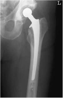
Antero-posterior hip image showing a ‘Thompson’s’ hip prosthesis
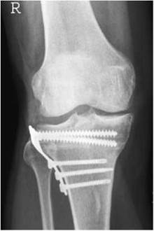
Antero-posterior knee image showing an example of a tibial osteotomy
Trauma orthopaedic surgery
• The orthopaedic surgical procedures highlighted previously are necessary to correct defects in paediatric bone and joint alignment. However, the majority of the radiographer’s workload in the theatre environment will focus on trauma orthopaedic surgery, assisting the successful reduction of fractures and the implantation of internal or external fixing devices.
• There are various trauma orthopaedic procedures where radiographic imaging is required. The table opposite provides examples of familiar trauma operative procedures in relation to fracture types.
• Image examples and important factors to note during the imaging procedure are provided on p. 372.
• A more extensive explanation of the typical dynamic hip screw (DHS) surgical and imaging procedure can be found on p.374.
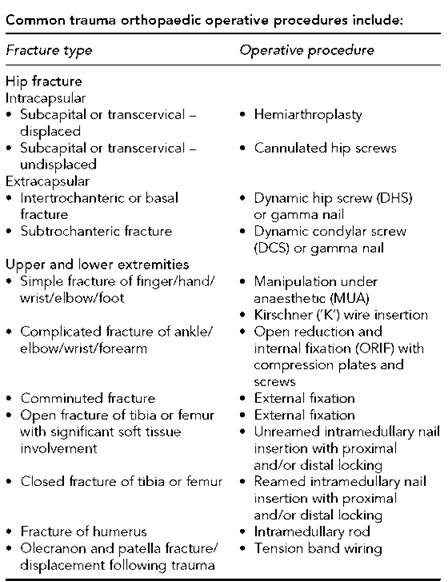

Diagram illustrating types of intracapsular and extracapsular hip fractures

Antero-posterior image of left hip showing extracapsular fracture
The Kirschner wire insertion is performed mostly in corrective simple fracture extremity surgery.
When positioning the image intensifier for this surgical procedure, it is important to ensure that the C-arm is rotated through 180 degrees, therefore placing the affected limb closest to the detector. This reduces magnification and improves image quality.
Open reduction and internal fixations (ORIFs) are performed mostly in complicated fractures where the fracture cannot be held satisfactorily by any other means, e.g. midshaft forearm fractures can be stabilized using compression plates and screws. Again, the image intensifier must be positioned with the affected limb closest to the detector, allowing minimum magnification and distortion of the image yet permitting ease of movement when positioning for both the antero-posterior and lateral images. Imaging control is often required at the end of this procedure as the surgeon can often visualize the fracture site due to the procedure being ‘open’.
External fixation and Steinmann pin insertions for traction often require imaging control to visualize the progress of the surgical procedure. Various external fixators are in use, ranging from the Ilizarov (ring fixator) to the AO ((Arbeitsgemeinschaft für Osteosynthesefragen) tubular) system. In either instance, image guidance is often required to demonstrate the true position of the screw or pin during surgical positioning and to aid in the reduc- tion/manipulation of the fracture site when the fixator is in place.
Tension band wirings, like ORIFs, are essentially an open surgical procedure. In these cases, imaging control to assist the surgeon is often kept to a minimum and is upon the surgeon’s request.

Example of tension band wiring

Example of Kirschner wire insertions
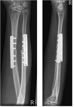
Example of internal plates and screws in forearm following ORIF
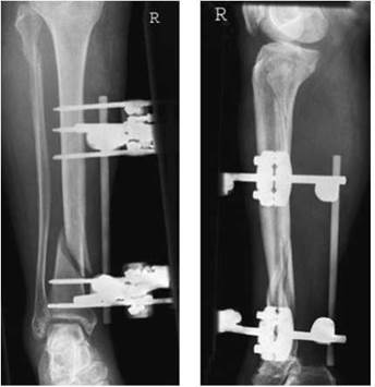
Example of external fixation of tibia and fibula

Example of intramedullary nail insertion in the femur (hip down)
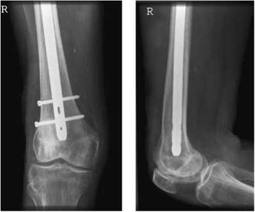
Example of intramedullary nail insertion in the femur (knee up) showing distal locking
Intramedullary nailing requires intermittent imaging control throughout the majority of the surgical procedure, not only to assist the surgeon in visualizing the nail as it passes through the medulla of the long bone but also, more importantly, to assist in the proximal and distal locking of the nail with cortex screws.
During the proximal and/or distal locking of the surgical procedure, the radiographer must aim to image the nail within the medulla of the long bone, demonstrating the circular holes within the nail en face, thus allowing the surgeon to insert the cortex screws with ease. Laser guidance facilities are available on some image intensifiers to assist in this procedure.
Cannulated hip screws are used mostly for undisplaced subcapital or transcervical fractures. The imaging procedure for this technique is similar to the DHS procedure, which is discussed in more detail in the following section.
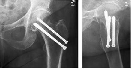
Example of cannulated screws in different patients
Dynamic hip screw insertion
Introduction
The procedure described for a DHS insertion is typical of that employed in an orthopaedic theatre. There are, however, a number of variations to be found in the approach of different surgeons, and the radiographer should be aware of the technique employed in their own hospital.
The technique described employs the use of a sterile protective barrier, which separates the image intensifier from the surgeon and the operative field.
During the operative procedure, images of the hip and neck of femur are taken at right-angles at various stages. Care should be taken, therefore, when moving the imaging intensifier into these required imaging positions to ensure that the sterile field is not compromised.
Imaging procedure
A mobile C-arm image intensifier is preferred for this procedure as it provides a real-time image to assist the surgeon in positioning the guide wire and subsequent DHS internal fixator. Ideally, image intensifiers in use should be equipped with a memory device that gives an immediate playback of the image last seen on the television screen. Most modern image intensifiers fulfil this requirement.
Using a system equipped with a memory device helps to reduce the radiation dose to the patient, since the surgeon is able to study an image without further irradiating the patient. This also allows the surgeon to store the last image, so that comparisons can be made of any alterations to the position and direction of the guide wire or DHS. In addition, hard-copy images can be taken at the end of the operation to help demonstrate the completed procedure.
Before the operation commences, the patient, whilst anaesthetized, is transferred to a special orthopaedic operating table with leg supports. The patient is positioned by the orthopaedic surgeon with the unaffected leg raised, flexed and in abduction, and the affected leg extended and in medial rotation. Traction is applied to the affected limb, enabling manipulation and alignment of the fracture site.
At this stage, the mobile image intensifier is positioned to enable screening of the hip in both the postero-anterior and lateral directions. The long axis of the intensifier is positioned between the legs and adjacent to the unaffected limb, enabling the C-arm to be rotated through 90 degrees, parallel to the neck of the femur. Once positioned correctly, the image intensifier is locked into position and checked to ensure that the C-arm rotates freely from the postero-anterior to lateral imaging positions and that the femoral neck is imaged in the middle of the image intensifier face.
As the image intensifier is positioned on the opposite side of the sterile protective barrier, a sterile cover is not required (see page 368). However, a plastic protective cover is placed over the X-ray tube housing to protect the X-ray tube covering in the event of blood spillage from the operative site.

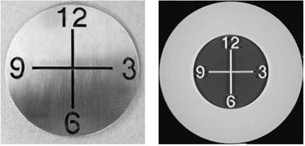
Example of a radio-opaque clock device used for orientation of an image intensifier and an X-ray image of the device
During the surgical/imaging procedure, the radiographer makes appropriate alterations to exposure factors and orientation controls. The use of a radio-opaque clock device is invaluable in determining the correct orientation of the hip joint. A record is made of the total screening time and radiation dose employed during the operation.

Antero-posterior and lateral hip diagrams showing a reduced fracture

Antero-posterior and lateral hip diagrams showing a guide pin positioned through the centre of the neck of the femur

Antero-posterior and lateral hip diagrams showing insertion of a lag screw
Dynamic hip screw insertion
Surgical procedure
The diagrams opposite illustrate the typical images that are acquired during an operative procedure using the DHS.
For this procedure, a DHS guide pin and angle guide are first required. The guide pin is positioned through the centre of the neck of femur and an appropriate triple reamer is placed over the guide pin to allow a channel to be reamed for the insertion of a lag screw. When the channel is completed, the lag screw is inserted, with the threaded tip lying approximately 10 mm from the joint surface. A DHS plate is then placed over the distal end of the lag screw assembly and positioned until it is in contact with the lateral cortex of the proximal femur. Cortex screws are then used to secure the DHS plate in position.
Imaging is necessary during the procedure to demonstrate:
• the fracture before it is reduced;
• the fracture reduced, with the angle guide and guide pin during positioning;
• the reaming of a channel before the insertion of the lag screw;
• insertion of the lag screw and DHS plate;
• completed operation, with a DHS inserted to stabilize the fracture site.
As outlined earlier, there are a variety of other operative procedures for the treatment of intertrochanteric and femoral neck fractures. Common to each technique adopted is the placing of guide pins along the femoral neck and into the head of the femur before the insertion of screws or securing plates.
Whist acquisition of images during these operative procedures is a dynamic process, with images acquired at each stage in the postero-anterior and lateral planes, permanent images are acquired at the end of the procedure for completeness. These images are best acquired using the image intensifier memory device, since this reduces radiation dose to the patient and staff. It is important, however, that the hip joint and proximal end of the femur are demonstrated to ensure that the full extent of fixation plates, pins and screws can be seen on these images.
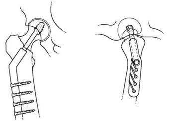
Antero-posterior and lateral hip diagrams showing the completed operation with lag screw and DHS plate secured in position
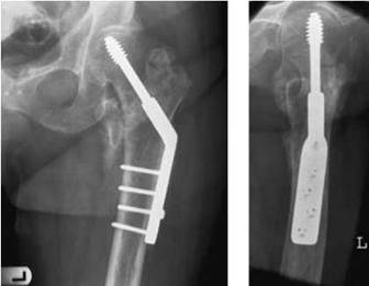
Antero-posterior and lateral images of the hip showing a DHS implant
Interventional urology
Introduction
Interventional urology plays an important role in the theatre setting, particularly for those patients who require general anaesthesia. The following procedures are typical examples:
• retrograde pyelography;
• percutaneous nephrolithotomy.
Retrograde pyelography
Retrograde pyelography, also known as ascending pyelography, involves a mechanical filling procedure to demonstrate the renal calyces and pelvis with a suitable organic iodine contrast agent.
A theatre table suitable for cystoscopy, with a radiolucent top, is used. The mobile image intensifier with a C-arm is usually selected to provide real-time images for the surgeon during the operation.
Cystoscopy is first performed to pass a catheter into the ureter and up to the pelvis of the affected kidney. Fluoroscopy may be needed to assist with this.
The patient is positioned supine during the operation.
Imaging procedure
• When a mobile image intensifier is employed, the intensifier is positioned on the opposite side of the table to which the surgeon is operating and moved into position over the operation site to adopt a postero-anterior projection of the abdomen. The patient is positioned on the table before the operation to ensure that the intensifier will move into position without being obstructed by the table's main support pillar.
• During fluoroscopy, between 5 and 20 ml of a 150-mgI/ml strength contrast agent is introduced via the ureteric catheter into the affected renal pelvis.
• Permanent images are acquired of the contrast-filled calyces and ureter using the machine's last-image-hold facility or an exposure technique.
• The catheter is withdrawn using fluoroscopy to observe the emptying of the contrast into the bladder.
• Images are acquired as and when required to record any abnormalities.
Note
This procedure may be undertaken in the imaging department as part of a two-staged procedure, with the patient having had the cystoscopy in theatre and catheter placement under anaesthetic and imaging subsequently undertaken in the radiology department.
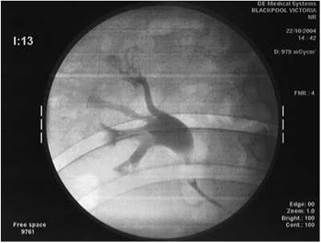
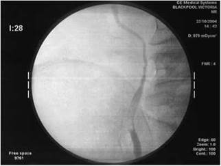

Above images demonstrate a contrast-filled renal collection system and ureter acquired in theatre using a mobile image intensifier and digital image capture device


Percutaneous nephrolithotomy
Percutaneous nephrolithotomy (PCNL) is an interventional procedure used to remove renal stones directly via a nephrostomy tract.
A mobile image intensifier with a C-arm and a theatre table for cystoscopy with a radiolucent tabletop are usually selected for this procedure, since this provides a real-time fluoroscopy image of the positioning of catheters and instrumentation and the flow of contrast media through the renal tract.
Small stones less than 1 cm that have proved unsuitable for treatment by lithotripsy are removed by special instruments in conjunction with endoscopy. Larger stones, e.g. stag-horn calculus, require first to be disintegrated by electrohydraulic lithotripsy or ultrasound shock waves.

Imaging procedure
• With the patient supine on the operating table for cystoscopy, a retrograde catheter is placed in the renal pelvis or upper ureter on the affected side. This facilitates contrast medium (150 mg I/ml) and/or methylene blue solution to be injected into the renal pelvis throughout the procedure. The patient is then turned carefully into the prone oblique position, with the affected side uppermost.
• After opacification of the collecting system with contrast and/ or methylene blue solution, the posterior calyx of the lower calyceal group is punctured with an 18-gauge needle cannula. Imaging is performed as necessary during this procedure, with the C-arm vertical and angled obliquely across the long axis of the body to aid localization of the kidney.
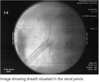
• Following removal of the central needle and aspiration of the mixture of urine, contrast and/or methylene blue to ensure accurate position within the collection system, a soft J-wire and then a stiff wire are passed in an antegrade manner into the kidney. The tract is then dilated up to a 30F size (1 cm) using either a series of plastic dilators or a combination of dilators and a dilation balloon. A 1-cm sheath is then placed over the largest dilator or dilated balloon directly into the renal pelvis.
• A nephroscope, with its light source, is passed through the sheath to visualize the collecting system and facilitate the passing of instruments required to disintegrate and remove the calculus. During the procedure, an irrigation system incorporated into the nephroscope will wash clear any calculus fragments from the renal pelvis. Attention should be paid to ensuring that any water spillage from this process does not come into contact with the image intensifier.
• At the end of the procedure, a pigtail catheter is left in the renal pelvis to allow antegrade drainage of the kidney and to perform antegrade contrast studies if required to check for residual stone fragments.
• Careful collimation of the X-ray beam should be employed during this long imaging procedure.
• Permanent images are acquired of the contrast-filled calyces using the machine's last-image-hold facility or an exposure technique.
Operative cholangiography
Cholangiography refers to the demonstration of the hepatic, cystic and bile ducts by direct injection into the biliary tree. The examination may be requested during cholecystectomy to demonstrate the presence of any gallstones within the biliary ducts. The patient will be positioned supine during the operation.
A mobile image intensifier with a C-arm and a theatre table with a radiolucent tabletop are often selected for this procedure as this provides a real-time image for the surgeon to assess the flow of contrast media through the biliary tree.
Alternatively, the examination is performed using a specially adapted theatre table with a radiolucent tabletop, a device commonly known as a 'Baker's tray', and a mobile X-ray machine. A 24 X 30-cm grid cassette with a fast film/screen combination is usually selected. This method does have limitations, since a film has to be processed, thereby adding a delay in the operation. Also, optimum selection of exposure factors is critical.
Imaging procedure
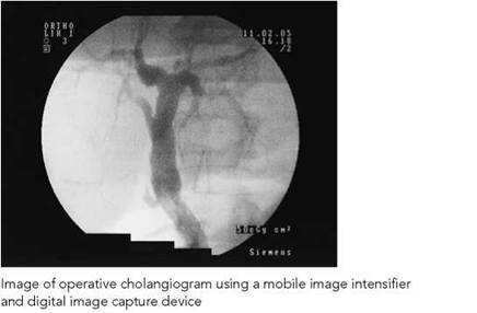
Mobile image intensifier
When a mobile image intensifier is employed, the intensifier is positioned on the opposite side of the table to which the surgeon is operating and moved into position over the operation site to adopt a postero-anterior projection of the abdomen. It is preferred that the patient is positioned on the table before the operation commences to ensure that the intensifier will move into position without being obstructed by the table's main support pillar.
Under carefully controlled conditions, the surgeon injects 20-30 ml of a water-soluble organic iodine compound (150 mg I/ml), without bubbles, into the biliary tract. The contrast is observed as it flows through the biliary tree into the duodenum.
Images of the contrast-filled biliary tree are acquired using the machine's last-image-hold facility or a single exposure technique.
Mobile X-ray machine
When a cassette tray (Baker's tray) mechanism is employed, an initial antero-posterior projection of the right upper abdomen may be taken before the operation. The cassette is positioned on the tray mechanism, offset relative to the centre to coincide with the right side of the abdomen. It is then moved to a position, using a long handle, along the table to coincide with the operation field, which should include the biliary tree and the duodenum. A note is made of the correct film position.
When required, antero-posterior projections of the abdomen are taken during and at the termination of the injection of contrast to ensure that any filling defect is constant and that contrast medium is seen flowing freely into the duodenum.
A 24 X 30-cm grid cassette (6:1 or 8:1 grid ratio) is used with a fast film/screen combination. Exposure is made using a significantly high kilovoltage technique of approximately 85-90 kVp in order to obtain a sufficiently short exposure time and a sharp outline of the biliary tree. In addition, movement blur may be reduced by the anaesthetist stopping the patient's respiration during the exposure.

Hysterosalpingography
Hysterosalpingography is commonly carried out in the general X-ray department, and nowadays is increasingly done using ultrasound and appropriate contrast media. However, a small percentage of examinations are carried out under general anaesthetic in theatre using radiographic contrast. (The procedure is described in detail in Whitley et al. 1999.)
The examination is requested to demonstrate the patency of the uterine tubes, demonstrating any cause of obstruction or abnormalities of the uterine cavity.
A mobile image intensifier with a C-arm and a theatre table with a radiolucent tabletop are selected for this procedure as this provides a real-time image for the surgeon to assess the flow of contrast media through the uterine cavity via the cervix.
The patient is positioned supine during the operation.

Imaging procedure
• The mobile image intensifier is positioned to adopt a postero- anterior projection of the lower abdomen/pelvic region.
• The patient is positioned on the table before the operation to ensure that the intensifier will move into position without being obstructed by the table's main support pillar.
• The patient is placed in the lithotomy position.
• Using an aseptic procedure, a speculum is introduced to dilate the vagina and a special cervical catheter is introduced through the cervix of the uterus.
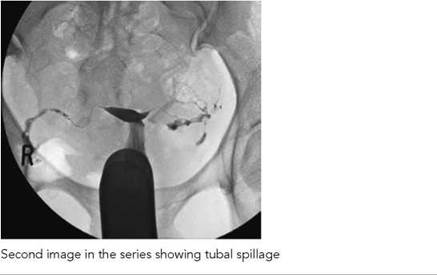
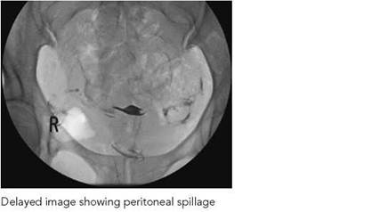
• Under carefully controlled conditions, the surgeon injects 10-20 ml of a water-soluble organic iodine compound (300 mg I/ml), without bubbles, into the uterine cavity so that spill into the peritoneal cavity can be seen. This should happen almost immediately with corresponding termination of the injection and withdrawal of the cervix adapter.
• The contrast is soon absorbed in the peritoneal cavity.
• Images of the contrast-filled uterus showing peritoneal spill are acquired using the machine's last-image-hold facility or a single exposure technique.
Note
During exposure, careful collimation of the X-ray beam is
employed to reduce the doses to the patient and the surgeon.
Emergency peripheral vascular procedures
Emergency angiography is sometimes performed in the theatre environment as part of corrective surgery to vessels following major trauma or bypass grafting to assess the patency of vessels.
A mobile image intensifier with a C-arm and a theatre table with a radiolucent tabletop are usually selected for this procedure. The C-arm will provide the surgeon with a real-time image of the flow of contrast media through the vessels. The procedure is best undertaken with a relatively large image intensifier with a generator capable of rapid image acquisition, subtraction, roadmapping and last-image-hold facilities and with two television monitors, one giving real-time display of imaging and the other showing post-processed images of the vessels in normal or subtracted modes.
The patient is positioned supine during the operation. An arterial catheter will be inserted, usually by Seldinger technique as described in Whitley et al. (1999).
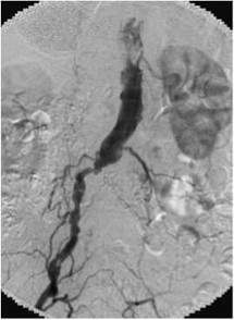
Angiogram of aorta showing complete occlusion of the left common iliac artery
Imaging procedure
Mobile image intensifier
When a mobile image intensifier is employed, the intensifier is positioned to adopt a postero-anterior projection of the affected area. The image intensifier face is positioned as close as possible to the skin surface to reduce magnification. For the lower limb, for instance, the patient is positioned on the table before the operation to ensure that the intensifier will move into position without being obstructed by the table’s main support pillar. The intensifier should be positioned with its wheels adjusted such that the intensifier can be moved, if necessary, along the length of the limb to follow the flow of contrast.
For subtraction angiography, the image intensifier is positioned over the region of interest, with the region screened to check for collimation of the X-ray beam. With the subtraction technique, selected fluorography is activated, following which up to 20 ml of a contrast agent (300 mg I/ml) is injected into the blood vessel (proximal to the affected site) and images are acquired as directed by the intensifier image acquisition software.
Continuous filling of the blood vessels with contrast agent is observed in the subtracted mode, showing the patency and any pathology of the affected vessel. An image acquisition rate of 1-2 frames/s (fps) is selected and run time is determined visually.
If necessary, a road-map technique may be performed, which facilities the accurate positioning of a catheter/guide wire under fluoroscopic control after first acquiring an image of the area of interest and then superimposing this image on the real-time fluoroscopic image.
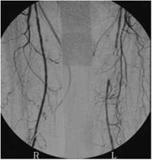
Angiogram of femoral arteries on 12-inch image intensifier, showing short segment occlusion of the left superficial femoral artery
