
Trauma radiography
Radiographers are aware that image quality is often compromised when examining a patient who has suffered acute trauma as their mobility and ability to cooperate is often reduced greatly. It is ironic that these patients, who require the highest-quality diagnostic images to detect the serious injuries associated with trauma, often will have a set of images that are of reduced quality as a result of their inability to cooperate.
Plain radiography of trauma, whether undertaken in the emergency room or within the imaging department, should therefore be considered as an imaging speciality in its own right. Radiographers undertaking these examinations need to have specialist knowledge that will help them to be aware of all the factors that reduce image quality and how to minimize their effects. It is beyond the scope of this section to give a detailed account of all the relevant imaging factors relevant to trauma radiography. However, it is possible to provide a series of points that all radiographers should be mindful of when undertaking any radiography of the acutely injured patient.

Assessment of the patient's condition
A vital first step in the examination is to scrutinize the imaging request and assess the patient's condition. An assessment of the mechanism of injury and a discussion with the patient (if possible) relating to their condition and capabilities will enable the radiographer to properly plan the examination for the maximum diagnostic outcome.
Planning the examination
When the radiographer is presented with a patient requiring multiple examinations, it is important to spend some time planning the whole examination so that it can be conducted efficiently, using the most appropriate equipment for the task.
Consider a patient who requires examinations of the whole spine, chest and pelvis. It would be more efficient if all the lateral radiographs were performed before all the antero-posterior radiographs. This avoids wasting time in moving the tube back and forth between exposures.
When examining patients on stretchers, it is also worth considering the side of any lateral examinations as the trolley enters the X-ray room. By doing this, the appropriate side of the body can be positioned against the vertical Bucky at this stage, rather than disrupting the examination halfway through by moving the trolley around.
Good communication with the accident and emergency (A&E) department staff is also of vital importance at the planning stage of any procedure. This will provide the radiographer with valuable information about the patient's condition and ability to cooperate. In addition, if the procedure is being undertaken as a mobile examination, then good communication is vital to ensure that the radiographer takes the correct equipment to the emergency room and correctly times their arrival in the department.

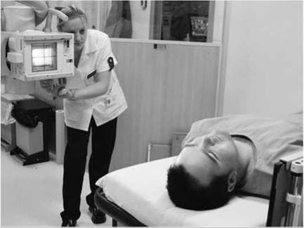
When undertaking trauma examinations involving multiple examinations, it will save time if all the examinations in one plane (e.g. laterals) are undertaken before others
Adaptation of technique

Horizontal beam lateral for knee examination
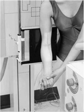
Antero-posterior elbow standing for supracondylar fracture

Accident and Emergency trolley with 30 X 40-cm cassette for lateral C spine
Much of the skill of a trauma radiographer stems from an ability to be able to produce radiographs of diagnostic quality when the patient is unable to cooperate to such an extent that the standard positioning cannot be undertaken.
It is beyond the scope of this section to give a full account of all the common adaptations that are used in trauma radiography. What has been provided is a series of general points and principles that radiographers should consider when presented with a difficult trauma case.
Horizontal beam laterals
This is an extremely useful adaptation that is used when the patient cannot move into the standard lateral position with a vertical central ray. In the example shown opposite, the use of a horizontal beam is actually advantageous to diagnosis. A lipo- haemarthrosis, which is a soft tissue indicator of injury within the knee joint, would not be visible if a standard lateral projection was performed.
Standing up/sitting
Patients may find it difficult to attain the standard positioning when the radiographs are undertaken in the usual seated or supine position. In such cases, asking the patient to stand up (if the condition will allow) may be beneficial. One good example of a situation where this is useful is in the case of a suspected supracondylar fracture of the elbow. The patient may not be able to extend the elbow to attain a good antero-posterior position whilst seated, but they may be able to do this if imaged erect.
Consider the pathology
The radiographer will constantly strive to produce standard projections that meet strict positioning criteria, but it is easy to forget to consider the pathology in question. This could lead to an important diagnosis being overlooked. An example of where this might happen is in a long bone when a joint examination is requested. The radiographer may not include an area of pathology in a long bone near to a joint if the radiation field is restricted to the joint region.
Be flexible
Radiographers should not become accustomed to doing things in a particular manner, otherwise they will become inflexible and unable to deal with unusual situations. Consider the cassette size used for lateral cervical spine radiography. In most cases, an 18 X 24-cm cassette would be used, but it is often difficult to support this cassette in a vertical position, especially in the resuscitation room. In such a situation, a 30 X 40-cm cassette resting on the trolley cassette tray may prove to be a useful alternative (see photograph opposite).
Patient's condition
It is important to closely supervise trauma patients at all times, as their condition can easily deteriorate. Patients who initially appear quite cooperative may suddenly become unstable and be in danger unless an appropriate intervention is made.
As discussed above, the patient's ability to cooperate will have a strong bearing on the quality of the final images. For the most part, there is nothing that can be done when a patient cannot cooperate, other than to adapt the imaging technique accordingly. There are some situations, however, when the radiographer may have some control over the patient's ability to cooperate. Some of these are outlined below.
• The intoxicated patient: in the absence of serious trauma, if possible delay the examination until the patient is sober enough to cooperate fully. This is particularly important for regions of the body where injuries can be difficult to diagnose. The quality of facial-bone radiographs obtained using a skull unit are far superior to those taken with the patient supine on a trolley. It would be unwise or even dangerous to attempt a facial-bone examination using a skull unit on a patient who is heavily intoxicated.
• Delaying the examination may also be considered when the patient's ability to cooperate is restricted severely by immobilization devices or clothing. Once other injuries have been excluded, these devices may be removed and the patient may be more able to cooperate.

A typical room suitable for trauma imaging

Range of immobilization devices commonly used in trauma imaging
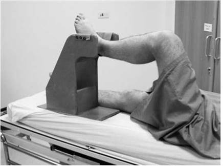
Leg support used for lateral hip imaging
Equipment and imaging considerations
Several X-ray equipment manufacturers offer a range of dedicated systems for trauma radiography. These are certainly useful in terms of time-saving and image quality when undertaking multiple procedures. It is possible, however, to obtain images that are equally as good as those taken using dedicated systems using a general X-ray room equipped with a ceiling-suspended tube, a vertical Bucky, a floating-top table with Bucky, and appropriate emergency equipment. A skull unit, although not essential, will increase the quality of skull and facial-bone images. One of the most desirable features of a room used for trauma radiography is space. If the radiographer has a generous space allocation, then this will give them greater flexibility when adaptations in technique are required.
Other more specific considerations are considered individually.
Immobilization devices
Any room used for trauma radiography should have a generous supply of radio-lucent foam pads and sandbags for supporting patients or cassettes. Specialist devices, such as the leg support used for lateral hip radiography, are often invaluable.
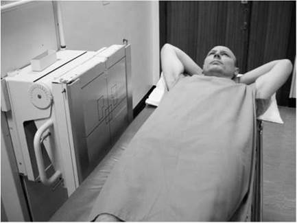
Increase in object-to-film distance leading to greater geometric unsharpness
Equipment and imaging considerations
Grids
Adaptations in technique will often result in the use of stationary grids for trauma radiography. These should be used only as a last resort due to the poor efficiency of such grids in terms of scatter attenuation compared with that of a Bucky with a moving grid mechanism. The grid lattice pattern from the stationary grid, and the relatively low grid ratio, contribute to a lower image quality when stationary grids are used. The type of grid is also important. If a focused grid is employed, then the radiographer must ensure that the correct focus-to-film distance (FFD) for the type of grid is used, otherwise a ‘cut-off artefact will result.
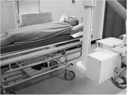
Increased focus-to-film distance to reduce geometric unsharpness

Example of a trolley well suited for Accident and Emergency imaging
Object-to-film distance
In many cases, an increase in object-to-film distance (OFD) will result from the modifications in technique required in trauma radiography. A good example is the horizontal beam lateral radiograph of the thoracic or lumbar spine. If the patient is lying in the middle of the trolley, then the spine will often be positioned at some distance from the cassette. This results in an increase in magnification and geometric unsharpness. The problem is easily remedied by increasing the focus-to-object distance (FOD) (within the focus range of the grid) to compensate. Remember that if this strategy is employed, and no automatic exposure device is used, then the radiographer must increase the exposure factors.
Collimation
Many trauma radiographic examinations are prone to high levels of scattered radiation that degrade overall image quality. A good example of such an examination would be the horizontal beam lateral lumbar spine, as described above. The extra tissue from the abdominal viscera lying either side of the spine increases the amount of tissue irradiated compared with a standard lateral, and there is a corresponding increase in scatter production. In such cases, close attention to collimation is important, as this will serve to vastly decrease the scatter produced and will significantly improve image quality.
Type of trolley
There are many different types of trolley available for use in A&E work, some of which are far more suitable for plain film imaging than others. It is strongly recommended that radiographers maintain close links with A&E staff so they can involve themselves with the purchase of new trolleys. A period of evaluation when any potential new trolley is tested in practice is essential as part of the procurement process. Some relevant considerations with respect to trolley design are highlighted on the next page.
Equipment and imaging considerations (contd)
Cassette holder
The trolley must have either a moveable tray underneath the patient to accommodate cassettes and grids or a wide platform that runs the length and width of the trolley. The latter may offer greater flexibility if the patient is not central to the trolley. Alternatively, separate cassette holders are available or can be made to suit a particular purpose.
Access to cassettes
Whichever method is used to support the cassette underneath the trolley, it is important that the radiographer can easily gain access and view the cassette wherever it is positioned relative to the patient. This is vital for accurate alignment of the cassette to the beam before exposure.
Object-to-film distance
The distance between the trolley top and the cassette holder underneath should be as small possible but still allowing reasonable access for the positioning of cassettes. If this distance increases, then geometric unsharpness will also increase, thus reducing image quality.
Uniform trolley top
The trolley top should be completely radio-lucent (no metal bars or hinges) and designed in such a way that there is a minimum of joins in the material that the trolley top is constructed of. These may cause artefacts on any images taken using the cassette holder underneath the patient.
Vertical cassette holders
Some trolleys come equipped with vertical cassette holders, which are useful, but not vital, for performing horizontal beam lateral examinations.
Image artefacts
Artefacts from clothing or immobilization devices applied by ambulance staff are an ongoing difficulty for radiographers to deal with. Necklaces or earrings under rigid neck collars cause many problems, as the radiographer may not be aware of their presence until an image is obtained. Again, the establishment and maintenance of good communication links between professional groups will allow communication of such problems and raise awareness of the difficulties that arise as a consequence.
Teamwork
When imaging trauma patients, the efficiency and effectiveness of a radiology department will spring from good teamwork. This applies between professional groups as well as within the radiology department. Close links between radiology and the A&E

Example of a trolley cassette holder well suited for Accident and Emergency imaging

Trolley cassette holder used for horizontal beam imaging

Example of artefact obscuring a spinal fracture
department will help each group to understand their respective difficulties and will help to overcome problems and maximize efficiency. When imaging a patient who has suffered multiple trauma, a team of two - one radiographer positioning the patient and the other processing the images - will serve to maximize efficiency.
Exposure factors
Trauma radiography often requires adaptations in exposure factors due to the non-standard imaging conditions encountered. Some considerations that the radiographer should be aware of are listed below:
Reducing exposure time
If movement unsharpness is likely, then the exposure time can be reduced in a variety of ways:
• Increase the kVp and reduce the mAs.
• If possible, increase the tube mA and reduce the exposure time.
• Increase the tube loading to 100%. Most generators are routinely operated at a loading of less than this.
• Consider using a faster imaging system and thus reducing exposure time.
• Use of a broad focal spot will allow a shorter exposure time.
Enhance contrast
Consider altering the kVp to manipulate the image contrast. A low kVp will be useful for demonstrating foreign bodies such as glass or for highlighting a subtle fracture. A high kVp may be useful for reducing large differences in subject contrast - differing regions within spine being a good example.
Exposure latitude
Systems that offer wide exposure latitude are particularly useful, as they are more able to cope with the variations in conditions encountered in the trauma setting. The digital systems are particularly useful in this respect.
Automatic exposure devices
These are advantageous for trauma imaging, particularly those located in the erect Bucky, which are used for horizontal beam spinal imaging. Care should always be taken to ensure that the tube is centred correctly to the Bucky at all times, otherwise the device will not give the correct exposure. It is easy to decentre the tube from the Bucky whilst making fine alterations to the final centring point.
Correct labelling of images
Given the many modifications in technique often employed in trauma radiography, it is important that the final image is labelled correctly (e.g. supine, erect, horizontal beam, etc.) so an accurate diagnosis can be made.
Advanced Trauma and Life Support (ATLS)
This is a comprehensive protocol introduced by the American College of Surgeons to ensure that any patient suffering major trauma is given adequate emergency care, even remote from a major trauma centre, thus allowing patients to arrive at a centre of excellence in the best possible condition. The ATLS workbook specifies minimum standards of care to all body systems from a variety of viewpoints, including specifications for radiographic examination. It is also being widely adopted outside the USA.
According to protocol, the initial radiographic assessment of the severely injured patient includes: lateral cervical spine, chest X-ray (CXR) and pelvis. N.B. skull X-ray is not included.
These are performed immediately as part of the initial assessment and before full clinical examination. Following full clinical evaluation, further projections or projections of other areas may be requested. At some point (determined by the clinical priorities), full projections of the cervical spine should be obtained.
The definition of ‘full projections' will be determined by local protocols, but is usually three projections (antero-posterior, lateral, peg), with the addition of trauma oblique projections in some centres. If adequate basic projections are not obtained, then the use of computed tomography (CT) may become necessary, again as determined by local guidelines. CT is not a quick examination in the unconscious, ventilated patient, and it can be a high-dose examination. It should not be viewed as an easy alternative to good plain-film radiography.
ATLS also calls for flexion projections of the cervical spine under supervision of an experienced doctor, prior to full ‘clearance' of the spine in patients who are alert and neurologically normal but suffering neck pain. Flexion of the spine in an injured patient should be undertaken only under medical supervision.
As 7-10% of patients with cervical spine fracture have an associated fracture of the thoracic or lumbar spine, projections of these areas may also be indicated.
Significant injury to the thoracic and lumbar spine can occur without local tenderness or pain, especially in the presence of a painful lesion elsewhere. It may therefore be appropriate to perform full spine projections in patients with major trauma and other painful lesions, as well as those with depressed level of consciousness and those with cervical spine injury.
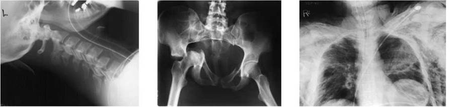
ATLS series of trauma images showing a fracture dislocation of C5/C6, unstable pelvic fractures and a chest image showing pneumothorax and surgical emphysema
Many different objects may enter body tissues and cavities under a variety of circumstances. The main methods of entry are:
• percutaneous
• ingestion
• inhalation
• insertion
• transocular.
If the foreign body is non-metallic and a similar sample of the object is available, then the sample may be placed in a few centimetres depth of water in a non-opaque container and radiographed to establish its radio-opacity. The method adopted to demonstrate the presence and position of a foreign body is governed by its size and degree of opacity and its location. Unless it is radio-opaque or in a position where it can be coated with opaque material to render it visible - as, for instance, in the alimentary tract - then the foreign body cannot be shown on a radiograph. Partially opaque foreign bodies, such as wood, some types of glass and other low-density materials, may sometimes be shown by suitable adjustment of the kVp.
Although the spatial resolution of computed radiography (CR) and direct digital radiography (DR) may be inferior to conventional imaging, the electronic post-processing capabilities of these systems more than compensate. The ability to adjust the image using image magnification, edge enhancement and windowing tools make the presence of a foreign body more easily visualized. Additionally, the contrast resolution of CR and DR is greater than that of conventional imaging, making it possible to visualize foreign bodies previously not seen on radiographs (e.g. splinters of wood).
Removal of bulky dressings from soft tissue lacerations is recommended, especially when using CR and DR, as these artefacts become more obvious on the image and can obscure radioopaque foreign bodies such as glass fragments. Matted blood in the hair can also prevent glass splinters in the scalp from being seen.
Ultrasound is useful in the localization of non-opaque subcutaneous foreign bodies and the genital system.
CT or magnetic resonance imaging (MRI) may be used when it is necessary to demonstrate the relationship of a foreign body to internal organs.
Notes
• MRI must not be undertaken if there is any possibility that the foreign body is composed of ferromagnetic material.
• Before commencing any examination, it is important to ensure that no confusing opacities are present on the clothing, skin or hair on the tabletop, Bucky, cassette or intensifying screens, or on the Perspex of the light-beam diaphragm.

Photograph of samples of wood, glass and metal objects

Radiograph of the objects seen above X-rayed through a wax block - note the thin sliver of wood and thorn wood is barely visible
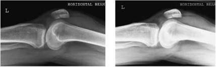
Images of a left knee acquired using a computed radiography system: left, windowed for normal viewing; right, windowed for soft tissues (here demonstrating more clearly a joint effusion in the suprapatellar bursa)

Lateral neck image showing the effect of braided hair with streak-looking structures superimposed over the soft tissue neck region
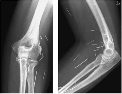
Antero-posterior and lateral images of a right elbow demonstrating multiple needle insertions
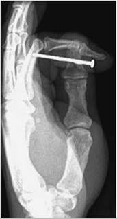

Dorsiplantar and lateral images of the thumb showing embedded nail in the distal soft tissues

Examples of glass foreign bodies illustrating that the density on the image will vary depending on the thickness and lead content of the glass
Percutaneous foreign bodies
These are commonly metal, glass or splinters of wood associated with industrial, road or domestic accidents and self-harm injuries.
Generally, two projections at right-angles to each other are required, without movement of the patient between exposures, particularly when examining the limbs. The projections will normally be antero-posterior or postero-anterior and a lateral of the area in question, as described in the appropriate chapters.
A radio-opaque marker should be placed adjacent to the site of entry of the foreign body. The skin surface and a large area surrounding the site of entry should be included on the images, since foreign bodies may migrate, e.g. along muscle sheaths, and high- velocity foreign bodies may penetrate some distance through the tissues.
Compression must not be applied to the area under examination.
Oblique projections may be required to demonstrate the relationship of the foreign body to adjacent bone. A tangential (profile) projection may be required to demonstrate the depth of the foreign body and is particularly useful in examination of the skull, face, and thoracic and abdominal walls. Sometimes a single tangential projection may be all that is required to show a superficial foreign body in the scalp or soft tissues in the face.
The exposure technique should demonstrate both bone and soft tissue to facilitate identification of partially opaque foreign bodies and to demonstrate any gas in the tissues associated with the entry of the foreign body.
The most usual exposure techniques for conventional radiography are:
• kVp sufficiently high to demonstrate bone and soft tissue on a single exposure;
• use of two film/screen combinations of different speeds or a film/screen combination and non-screen film to demonstrate bony detail on one film and soft tissue on the other film with one exposure.
The use of digital image acquisition offers significant advantages in the localization of foreign bodies. CR and DR both allow soft tissue and bone to be visualized from one exposure using postprocessing. The use of features such as edge enhancement and windowing enable much better demonstration of foreign bodies that have radio-opacity similar to that of the surrounding tissue.

Tangential (profile) projection of the scalp showing glass embedded in the soft tissues
Ingested foreign bodies
A variety of objects, such as coins, beads, needles, dentures and fish bones, may be swallowed accidentally, or occasionally intentionally, particularly by young children. A technique used to smuggle drugs through customs involves packing the substance into condoms, which are subsequently swallowed.
The patient should be asked to undress completely and wear a hospital gown for the examination. The approximate time of swallowing the object and the site of any localized discomfort should be ascertained and noted on the request card, along with the time of the examination. However, any discomfort may be due to abrasion caused by the passage of the foreign body. It is important to gain the patient’s cooperation, especially in young children, since a partially opaque object may be missed if there is any movement during the exposure. The patient should practise arresting respiration before commencement of the examination.
If the patient is a young child, then the examination is usually restricted to a single antero-posterior projection to include the chest, neck and mid- to upper abdomen. The lower abdomen is usually excluded, to reduce the dose to the gonads, as the examination is usually performed to confirm the presence of a foreign body lodged in the stomach unable to pass through the pylorus. Care must be taken to ensure that the exposure selected is sufficient to adequately penetrate the abdomen as well as to visualize the chest.
The examination of older children and adults may require a lateral projection of the neck to demonstrate the pharynx and upper oesophagus, a right anterior oblique projection of the thorax to demonstrate the oesophagus, and an antero-posterior abdomen projection to demonstrate the remainder of the alimentary tract, exposed in that order. Each image should, preferably, be inspected before the next is exposed, and the examination terminated upon discovery of the foreign body, to avoid unnecessary irradiation of the patient. The cassette used should be large enough to ensure overlapping areas on adjacent images.
Non-opaque foreign bodies may be outlined with a small amount of barium sulphate. A few cases require a barium- swallow examination. If no foreign body is demonstrated within the alimentary tract, and particularly if there is doubt as to whether the foreign body has been ingested or inhaled, then a postero-anterior projection of the chest will be required to exclude an opaque foreign body in the respiratory tract or segmental collapse of the lung, which may indicate the presence of a non-opaque foreign body in the appropriate segmental bronchus. All projections should preferably be exposed in the erect position. A fast film/screen combination and short exposure time should be employed.


Lateral soft tissue image of the neck showing a fish bone lodged in the larynx
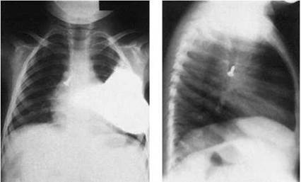
Antero-posterior and lateral chest images showing a screw lodged in the right main bronchus
Inhaled foreign bodies
Foreign bodies may be inhaled. Infants and young children habitually put objects into their mouths, and these may be inhaled. Teeth may be inhaled after a blow to the mouth or during dental surgery. Such foreign bodies may lodge in the larynx, trachea or bronchi.
The adult patient should be asked to undress completely to the waist and to wear a hospital gown for the examination. A postero-anterior projection of the chest, including as much as possible of the neck on the image, and a lateral chest projection will be required initially. Alternatively, an antero-posterior chest image is acquired when examining children. A lateral projection of the neck, including the nasopharynx, may also be required. In the case of a non-opaque inhaled foreign body, postero-anterior projections of the chest in both inspiration and expiration will be required to demonstrate air trapping due to airway obstruction. This may manifest itself as reduced lung attenuation on expiration and/or mediastinal shift. The kVp must be sufficiently high to demonstrate a foreign body that might otherwise be obscured by the mediastinum. A fast imaging system (film/screen combination) and short exposure time should be employed.
Cross-sectional imaging such as CT and MRI are additional techniques that may provide useful information. NB: MRI is contraindicated in cases of suspected ferrous materials, since the examination may result in movement of the foreign body.
Bronchoscopy may be used to demonstrate the position of a foreign body, since the foreign body may be removed during this procedure.

Inserted foreign bodies
Foreign bodies are sometimes inserted into any of the body orifices. Infants and young children, for example, may insert objects into the nasal passages or an external auditory meatus. In these cases, radiography is required only occasionally, since most of these objects can be located and removed without recourse to radiography.
When radiography is requested, two projections of the area concerned at right-angles to each other will be required.
Swabs may be left in the body following surgery. Such swabs contain a radio-opaque filament consisting of polyvinylchloride (PVC) impregnated with barium sulphate for radiographic localization.
Ultrasound should be the initial modality selected for the detection of an intrauterine contraceptive device. It is also very effective in the detection of soft tissue foreign bodies with the advantage of incurring no radiation burden where it is available.
There have been incidents where objects such as vibrators have become lodged in the rectum. In these cases, a single anteroposterior projection of the pelvis may be required.
Patients who are prone to self-harm may insert a variety of objects into their body cavities and under the skin.
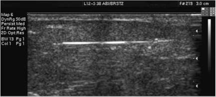
Ultrasound image of a needle in the superficial soft tissue
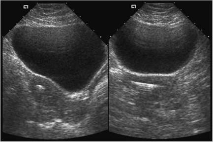
Ultrasound image of an intrauterine contraceptive device
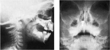
Lateral and postero-anterior facial images showing a screw in the right nasal cavity
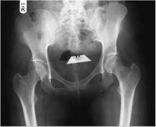
Antero-posterior pelvis showing a Stanley knife blade inserted in the vagina

Antero-posterior pelvis showing a vibrator inserted in the rectum

Portable antero-posterior chest taken in theatre to locate missing swab
Foreign bodies that enter the orbital cavity are commonly small fragments of metal, brick, stone or glass associated with industrial, road or domestic accidents.
Plain film imaging is the first modality for investigation of a suspected radio-opaque foreign body in the orbit. For further investigation, or assessment of a non-opaque foreign body, CT scanning can be very useful. CT will give information about damage to the delicate bones of the medial and superior orbital
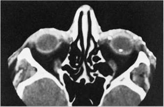
CT image showing multiple foreign bodies
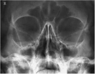
Modified occipito-mental image taken to detect the presence of a radio-opaque foreign body (normal)
Transocular foreign bodies
margins, and evidence of any damage suffered by the brain if the orbital roof has been breached. Ultrasound is useful for detecting superficial foreign bodies and soft tissue damage but is less useful in the orbit in detecting very small foreign bodies. Access to ocular ultrasound expertise is less likely to be immediately available, and there is the extra hazard of introducing coupling gel into a possibly deep wound.
Radiographic localization may be carried out in two stages:
• To confirm the presence of an intra-orbital radio-opaque foreign body.
• To determine whether the foreign body is intra- or extra-ocular.
Images showing fine detail are essential. A small focal spot (e.g. 0.3 mm2), immobilization with a head band and a high- definition film/screen combination is recommended. Metal fragments down to 0.1 X 0.1 X 0.1 mm in size may be detected by conventional radiography.
Intensifying screens must be scrupulously clean and free of any blemishes producing artefacts that could be confused with foreign bodies. A cassette with perfectly clean screens may be set aside especially for these examinations.
Confirmation of a radio-opaque foreign body
A modified occipito-mental projection with the orbito-meatal base line(OMBL) at 30 degrees to the cassette is undertaken, with the patient either prone or erect. Whichever technique is adopted, the head must be immobilized. The technique is described in detail on page 269. Ideally, a dedicated skull unit is selected as this will provide the maximum degree of resolution required for the visualization of a small foreign body.
The chin is raised so the OMBL is at 30 degrees to either the vertical or horizontal beam. This position projects the petrous ridges to just below the inferior, anterior orbital margin with the walls of the orbit lying parallel to the cassette. Using a vertical or horizontal beam, the central ray is directed to the interpupillary line. The beam is either collimated to include both orbits or just the orbit under examination, depending on the departmental protocol.
Notes
• If it is suspected that a foreign body is obscured by the skull then a soft tissue lateral image may be necessary.
• It may be necessary to repeat the examination if the artefact is suspected to be from a possible dirty screen.
• If a radio-opaque foreign body is identified in the orbit, before proceeding with any further localization images it may be advisable to wait until the patient has been seen by the ophthalmologist who may decide to remove the foreign body or request CT or ultrasound in preference to radiography localization.
Transocular foreign bodies (contd)
Localization of intra-orbital foreign body
The method described determines the position of the foreign body relative to the centre of the eye and whether it is intra- or extra-ocular. It should be ascertained that the patient is able to maintain ocular fixation, i.e. keep the eyes fixed on some given mark, since the exposures are required with the patient looking in different directions.
The examination is preferably carried out using a skull unit.
The following projections are required:
• Occipito-mental (modified) (see p. 269) with the centring adjusted to the middle of the interpupillary line. Two exposures are made, one with the eyes level and looking forward and the other with the eye under examination adducted (turned towards the nose).
• Lateral (see p. 267), with the centring adjusted to the outer canthus of the eye. Three exposures are made, one with the eyes level and looking forward, one with the eyes raised and one with the eyes lowered.
In each case, the patient should look steadily at some predetermined mark or small object during the exposure. A tracing is made from the lateral projections showing the three shadows of the foreign body. Straight lines are drawn to join them. The lines are then bisected at right angles midway between the shadows. The point of intersection of the bisectors indicates the centre of the eyeball if the intersection is slightly anterior to the zygomatic border of the orbit. In this case the foreign body is in the eyeball.
If the intersection is remote from the zygomatic border it will indicate that the foreign body is in the surrounding tissue or muscles.
A second tracing from the occipito-mental projections enables lateral movement of the foreign body to be plotted and shows its antero-posterior position relative to the centre of the pupil.
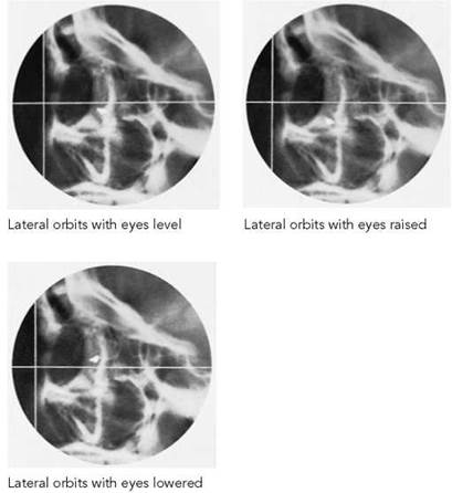

Tracing from lateral projections shows that the foreign body lies within the eye

Occipito-mental images with the eyes level (left) and the left eye adducted (right)

Tracing from occipito-mental projections shows that the foreign body lies posterior to the centre of the eye

Introduction
A conventional radiograph is a two-dimensional image formed by the superimposition of images from successive layers of the body in the path of the X-ray beam. The image of a structure in one layer of the body is observed with the superimposition on it of images of structures in layers above and below it.
Before the introduction and widespread use of CT, a technique known as (conventional) tomography was employed. This used conventional X-ray equipment, with tomographic attachments, or a dedicated tomographic unit to record images of structures or layers within the patient while images of structures outside the selected layer were made unsharp. There are several methods of achieving this, all of which involve some form of movement of the patient or equipment during the exposure, but in every case the general principle is the same. Throughout the exposure, movement occurs, causing images from the unwanted layers to move relative to the image receptor and therefore to be unsharp; images from the selected layer are kept stationary relative to the film and are recorded in focus. Tomography involves the synchronized movement of the X-ray tube and the cassette while the patient remains stationary. If there is movement only of the patient during the exposure, this is called autotomography.
Autotomography
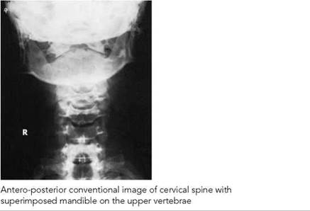
In this technique, the part to be visualized remains stationary during the exposure while overlying structures produce unsharp images due to some form of patient movement. The part to be visualized should be immobilized. A long exposure time is used to allow sufficient movement and therefore blurring of unwanted images.
The two most common applications of autotomography are as follows: an antero-posterior projection of the cervical spine, where the patient opens and closes the mouth during the exposure so that the mandible is not recorded as a sharp image obscuring cervical vertebrae; and a lateral projection of the thoracic vertebrae, where the patient continues gentle respiration during the exposure so that images of the ribs and lungs are unsharp, allowing better visualization of the vertebrae.

Principles
As stated previously, a tomographic image can be produced by relative movement between the patient, the image-recording device and the X-ray tube. In practice, this is normally achieved by the patient remaining stationary while the X-ray tube and the cassette move.
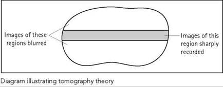
As the X-ray tube and cassette move relative to the patient, the projected images of structures at different levels of the body will move with different velocities. The nearer the structure is to the X-ray tube or cassette, the faster its image will move. The tube is linked to the cassette tray such that the cassette moves at the same velocity as images of structures only at the level of the pivot; therefore, only these images are recorded on the same part of the image receptor throughout the movement. Images of structures at or in all other layers move at a different velocity from that of the cassette and are not recorded on the same part of the image receptor throughout the movement and are therefore blurred.
It is therefore possible to record the outlines of structures more sharply on only one layer of the body free from obscuring images from other layers.
It is an important requirement that throughout the movement there is no change in the magnification of images on the object plane, since this would produce image unsharpness. To ensure constant magnification, the following relationship must be maintained throughout the movement: 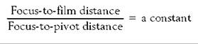

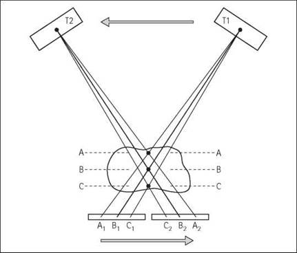
The X-ray tube is connected to the cassette and pivoted at B. When the X-ray tube moves from T1 to T2 during the exposure; images of layer B move at the same velocity as the image receptor and are recorded on the same part of the image receptor throughout the exposure and the image is sharp; images of layer A move faster than the image receptor and are therefore blurred; images of layer C move slower than the image receptor and are therefore blurred


Principles
The layer recorded sharply is called the object plane and it is parallel to the image receptor.
Normally, the image receptor lies parallel to the tabletop and therefore the object plane is parallel to the tabletop at the level of the pivot. If the image receptor lies at an angle to the tabletop, during the movement the layer visualized will be at the same angle. This is called inclined-plane tomography.
Depth of layer
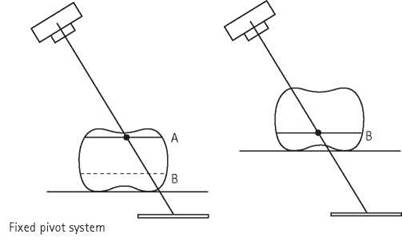
The height of the pivot table above the tabletop is variable so that any level in the patient can be selected for tomography. Either the pivot can be raised or lowered above the tabletop to the required level in the patient (variable pivot), or the pivot is in a fixed position and the tabletop can be raised or lowered to bring the required level to the level of the pivot (fixed pivot).
The height of the pivot above the tabletop is indicated on a scale. If the upper attachment of the connecting rod is at the level of the focal spot and the lower attachment is at the level of the cassette, then the layer recorded sharply is the layer at the level of the pivot that is parallel to the cassette. If the cassette is situated above or below the lower attachment of the connecting rod, then a layer above or below the pivot level will be recorded sharply.

Types of tomographic movement
Before the use of CT, when (conventional) tomography was used more widely, a variety of tube/film movements were employed to produce more effective blurring of unwanted structures, e.g. (in order of increasing complexity):
• linear
• circular
• elliptical
• spiral
• figure-of-eight (Lissajous figure)
• hypocycloidal.
Dedicated tomographic units were required for all movements other than linear. Since the use of conventional tomography is now limited mainly to imaging the renal tract, linear movement produces adequate blurring and we will only consider this movement in our discussions.
Features of linear movement
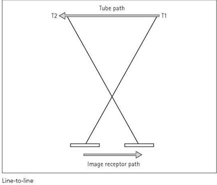
This is the simplest form of tomographic movement. The X-ray tube and image receptor move in lines parallel to the tabletop. The FFD changes throughout the movement, being least at the midpoint of the movement. Line-to-line movement is often confined to one direction only, which is along the long axis of the table, but some equipment will allow the linear movement to be in any direction parallel to the tabletop. There are different designs:
• Arc-to-line: the X-ray tube moves in an arc above the table while the image receptor moves below the table in a line parallel to the tabletop. This is typical of the majority of units. Throughout the movement, there is a change in the ratio of the focus-to-film/focus-to-pivot distance, resulting in a continual change in the magnification of images in the object layer. This results in some unsharpness, but if the change in magnification is kept to a small value then the image can be accepted by the observer as sharp.
• Arc-to-arc: the X-ray tube and the image receptor move in arcs, the centre of rotation being the pivot. Throughout the movement, the image receptor remains parallel to the tabletop and the FFD is constant.
NB: linear movements have the disadvantage that they produce ‘linear streaks’. These are pseudo-shadows caused by structures just outside the layer, which are incompletely blurred out and appear as indistinct linear images superimposed on the sharp image of the selected layer.
Exposure angle
The exposure angle is the angle through which the tube moves during the exposure. It is inversely related to the thickness of layer visualized on the image. For linear tomography, there is usually a choice of exposure angle ranging from about two to 40 degrees.


The above diagram demonstrates that during tube movement, the image of P (at the level of the pivot) is recorded on the same part of the film and is a sharp image. T is on a plane higher than the pivot and its image moves on the film from T1 to T2, but if this distance is not greater than about 0.6 mm it is still accepted as a sharp image. Therefore, the thickness of the layer extends up to T. There is a similar thickness of the layer below the pivot
Types of tomographic movement
Thickness of layer
Only images of structures at the level of the pivot and parallel to the film are recorded on the same part of the film throughout the movement. This layer is infinitely thin. Images of structures outside this object plane move relative to the image receptor, but if this movement is small (less than about 0.6 mm), they will be recognizable images. Therefore, the visualized layer has some thickness. The amount of relative movement of the image and therefore the thickness of the layer depends on the exposure angle, i.e. the angle through which the X-ray tube moves during the exposure. The greater the exposure angle, the thinner the layer. The layer has no well-defined boundary as there is a progressive deterioration in the sharpness of images of structures with increasing distance from the object plane.
Layer thickness also depends on the distance of the structure above or below the pivot. Images of structures above the pivot are more blurred than those below the pivot, and thus the layer is thinner above the pivot than below it. The practical significance of this is that structures close to the object plane can be ‘blurred out’ more easily if they are on the tube side of the patient (see the diagram opposite).

Types of tomographic movement (contd )
The graph shows how the thickness of the layer varies with exposure angle. At larger angles there is little change in layer thickness with change in exposure angle, whereas at small angles a small change in the exposure angle causes a large change in layer thickness.

Zonography
This is the term applied to small-angle tomography giving relatively thick layers. There is no fixed exposure angle below which tomography is classified as zonography, but the term is generally reserved for exposure angles of 10 degrees or less.
Thickness of cut and spacing of layers
For zonography, where the layer can be, for example, greater than 2 cm thick, layers at 2-cm intervals can be used. In practice, it is normal to use 10-degree exposure angles and 1-cm intervals. With wide-angle tomography, spacing of layers should be closer, to ensure that the layers overlap.
Magnification in tomography
As with all projected images, there is some magnification of a tomographic image. The magnification (M) is given by:


Generally, the quality of a tomography image, in terms of its sharpness and contrast, is not as good as that of a standard radiographic image.
Contrast
Because only a thin layer of the body is being recorded, inherent contrast is low, the problem being greater with the larger exposure angles that produce very thin layers. If the region is made up predominantly of soft tissue, then the layer might have to be at least 1 cm thick for contrast to be acceptable.
To improve contrast, particular attention should be paid to the control of scattered radiation by collimating the X-ray beam to the smallest possible field. A further method of improving contrast is to select the lowest kVp that will still give effective penetration.
Sharpness
As with a standard radiographic image, unsharpness can be due to patient movement (Um), focal spot size (Ug) and intensifying screens (Us). In addition, the tomographic movement can introduce a source of image unsharpness (Ut).
Particular attention should therefore be paid to the choice of focal spot sizes, immobilization and intensifying screens to reduce unsharpness to a minimum.
Exposure time and exposure angle
The exposure time and control of mA are undertaken automatically once the exposure angle has been selected. Automatic exposure control varies the mA continually during the exposure to ensure consistent film density.

Thick layer (zonogram) required to give contrast in soft tissue region
Image quality
Localization of the depth of the layer(s) required
The approximate depth may be known from past experience or from records kept of similar examinations. If not, then the depth of the layer can be estimated by studying antero-posterior and lateral radiographs.
Clearly, pivot heights will vary from patient to patient. They will also depend on whether a foam mattress is used and, if so, its thickness.
Radiation protection
The usual steps are taken to reduce the radiation dose to the patient, but there are some additional measures that are particularly applicable to tomography:
• The position and depth of the lesion should be localized accurately, preferably before the examination but if not then in the early stages of tomography.
• Whenever possible, the patient is positioned so that the structure of interest is parallel to the film, thus reducing the number of layers required.
• In skull tomography, position the patient prone wherever possible to reduce the radiation dose to the lens.
• The smallest field size compatible with a diagnosis is essential not only for radiation protection but also to improve radiographic contrast.
• The radiographer must follow an organized procedure for all stages of the examination to avoid the necessity of repeating exposure due to a careless omission.
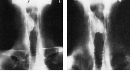
Thirty degrees linear. Contrast can be obtained in a thin layer containing air, bone and soft tissue
Procedure
The following procedure should be used as a guide in preparing and undertaking tomography:
• Having read and understood the request card, previous images should be studied for the localization of the position, extent and depth of the region to be visualized.
• The exposure angle to be used is selected with reference to the thickness of the zone containing the lesion and the shape of structures to be blurred out.
• An explanation of the examination is given to the patient. The patient is then positioned and immobilized on the table.
• The vertical central ray is directed to the centre of the region and the X-ray beam is well collimated.
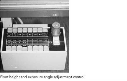
• The pivot height is set and the exposure angle is selected.
• The cassette carrying the appropriate radio-opaque legends is placed in position.
• The X-ray tube is moved to the starting position for the movement.
• The patient is given final instructions before the exposure is made.
• On viewing the tomography image, if it is satisfactory in terms of positioning, exposure, contrast and localization, any further required levels are taken.
• The pivot height is changed by a distance that depends on the thickness of the layers being recorded.

Exposure time and exposure angle
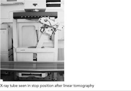
The exposure time selected should be greater than the time taken for the X-ray tube to complete the entire movement. This ensures that the exposure angle is symmetrical and that the anticipated angle, and hence layer thickness, is obtained. The choice of complex movements that require an exposure time of several seconds may be restricted if patient movement is a problem.
The use of variable-speed equipment allows for a choice of exposure time and mA for a given mAs.
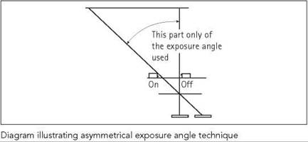
In some examinations, not all of the exposure angle contributes equally to image formation. In such cases, the exposure can be controlled to take place during part of the movement. For example, in linear antero-posterior tomography of the larynx (caudal ^ cranial), the exposure can take place only during the first part of tube movement.
Applications
The widespread availability of CT has resulted in a corresponding decrease in the use of conventional tomography. The main use conventional tomography is in intravenous urography examinations to reduce the effects of superimposed bowel gas. It may still be used for other structures where access to CT is limited or not possible.
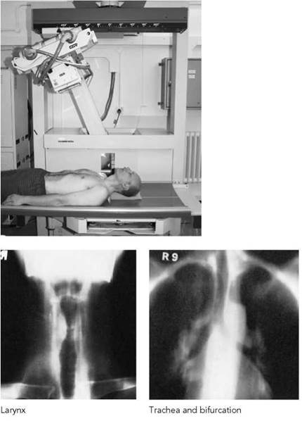
Two further applications - larynx and trachea - are included as examples.

Patient positioned for tomography of the renal areas - note that during IVU abdominal compression is usually in place

Five-minute post-contrast image with bowel gas obscuring the renal areas
Kidneys
In this situation, tomography is often used as a simple, cheap and relatively effective method of imaging the renal tract free of overlying structures. Since the structures that are required to be visualized are relatively thick (antero-posterior measurement), zonography, or narrow-angle tomography, is used to produce a large layer thickness.
Tomography is used during intravenous urography either at 10-20 minutes after injection, to diffuse the shadows of gas that overlie the calyces preventing their clear visualization, or immediately on completion of the injection to show the nephrogram stage. This latter method - nephrotomography - was used to differentiate between kidney cysts and tumour and between intra- and extra-renal masses, but has been actively superseded by ultrasound and CT.
Notes
Although a narrow angle, e.g. 10 degrees, can produce a large layer thickness (approximately 5 cm) and may enable the whole of the outline of the kidneys to be shown on one exposure it will not efficiently 'blur out' overlying bowel shadows in the bowel.
To 'blur' gas shadows a 20-degree, 30-degree or even a 40-degree angle may have to be used.

Tomography image showing the renal areas free from gas shadows and a mass in the left renal pelvic region
Antero-posterior
Position of patient and cassette
• The patient is supine on the table, with the median sagittal plane of the body at right-angles to and in the midline of the table.
Direction and centring of the X-ray beam
• The vertical central ray is centred in the midline, midway between the suprasternal notch and the symphysis pubis.
Pivot height
• 8-11 cm.
Note - if a mattress is used, then allowance for its thickness
must be made when selecting the pivot height.
Tomographic movement
• Linear 10 degrees - zonography.
• Linear 30 degrees - to blur out overlying bowel gas.
Larynx - antero-posterior
Position of patient and cassette
• The patient lies supine on the table, with the median sagittal plane of the trunk and head at right-angles to and in the midline of the table.
• The patient is located on the table so that a vertical central ray would pass 1 cm inferior to the eminence of the thyroid cartilage.
Pivot height
• From 0.5 cm deep to the skin surface to 4 cm deep to the skin surface.
Tomographic movement
• Linear longitudinal 20 degrees. With the X-ray tube moving in a caudal to cranial direction, the first half of a 40-degree movement can be used to avoid superimposing the images of the mandible and facial bones on to those of the larynx.
• Because the region is one of inherently high contrast, a high kVp (90 kVp) can be used; this reduces the amount of linear streaking recorded.
• Tomography may be taken during quiet breathing and also while the patient is phonating 'ee' to demonstrate an abnormal movement of the vocal cord due to a lesion.
Trachea - antero-posterior
The trachea passes downwards and slightly backwards from its commencement at the lower border of the cricoid cartilage to its bifurcation just below the level of the sternal angle. With the patient supine, the trachea makes an angle of about 20 degrees with the table, its upper end being further from the table than its lower end. To bring the trachea and the image receptor parallel either the lower trunk is raised on pillows or, if there is sufficient clearance between the cassette tray and the undersurface of the table, the cassette can be inclined about 20 degrees in the cassette tray by raising the edge of the cassette which is under the neck.
Position of patient
The patient lies supine on the table with the median sagittal plane of the trunk and head at right angles to, and in the midline of, the table. The lower trunk is raised as described above, which is essential if the patient has a marked lordosis. The patient is located on the table so that the vertical central ray would pass along the median sagittal plane midway between the cricoid cartilage and the sternal angle.
Pivot height
• 4-5 cm deep to the sternal notch.
Tomographic movement
• Linear transverse 10 degrees; may be followed by large angle movements if thinner layers are required.



Principles
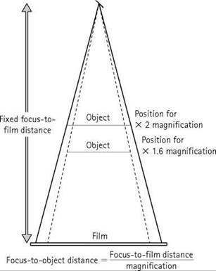
In some cases, it is helpful to the person making a diagnosis if the radiographic image can be enlarged, allowing smaller detail to become more obvious. Where digital image recording is used, this magnification can be obtained electronically. Using conventional film/screen technology, an alternative method of producing a magnified image is at the time of exposure, by increasing the object-to-recording medium distance; in this case, the X-rays diverging from a point source will produce a directly magnified image.
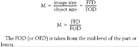
The magnification (M) can be calculated from:
Fixed focus-to-film distance
For a fixed FFD, magnification is increased by bringing the object nearer to the X-ray tube focus. The FOD for a given magnification is calculated from:

For example, with a fixed FFD of 100 cm, and if a magnification factor of one to six is required, then the FOD will be:

Fixed focus-to-object distance
So that the skin dose to the patient can be limited, the FOD is kept fixed at, say, 90 or 100 cm, and the required magnification is obtained by moving the film away from the object. The required OFD for a given magnification is than calculated from:

For example, if a magnification factor of one to six, is required at an FOD of 100 cm, then the required OFD will be:

Similarly, for a magnification factor of two at the same FOD, the required OFD will be:

Some equipment, e.g. the Orbix, has the facility for moving the cassette away from the object along a scale calibrated in magnification factors.
Principles (contd)
The technique of producing an image by direct magnification is called macroradiography. It has the advantage that although movement and geometrical unsharpness are increased compared with a technique using minimum OFD, there is no increase in photographic unsharpness. However, it must be remembered that such a magnified image will always be less sharp than one taken with the same focal spot with a minimum OFD.
A magnified image of acceptable sharpness will be produced only if movement unsharpness and geometrical unsharpness are kept to a minimum.
Movement unsharpness
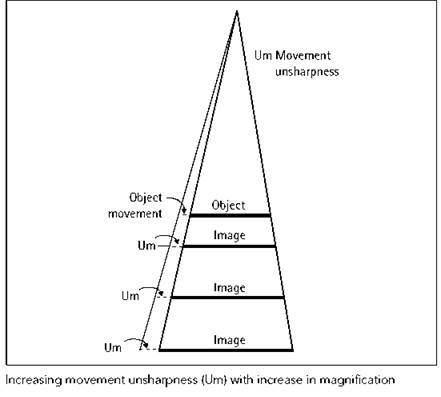
Direct magnification by increased OFD can be carried out only if there is complete immobilization of the patient, because any movement of the patient, be it due to lack of immobilization or involuntary movement, will be magnified on the radiograph due to the increased OFD. The technique, therefore, lends itself to producing magnified images of bony structures or structures contained within bone, e.g. the lacrimal ducts. For macroradiography, immobilization devices should be used, e.g. supports, binders, sandbags and pads, and the instructions should be given to the patient to remain still.
Geometrical unsharpness
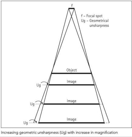
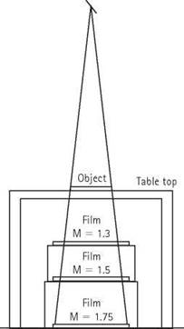
Geometrical unsharpness occurs because the source of X-rays is not a point source and any distance between the object and film will cause an image penumbra in addition to magnifying the image. Thus, for a given focal spot size, there is a limit to the magnification of the image beyond which the geometrical unsharpness is so great that significant detail is lost. The smaller the focal spot size, the greater the possible magnification of the image while still retaining acceptable image quality.
The relationship between image magnification (M) and focal spot size (f) with the corresponding geometrical unsharpness (Ug) is given by:
Ug = f(M - 1).
For example, if geometrical unsharpness is to be limited to 0.3 mm, then the maximum obtainable with the corresponding focal spot size is as follows:
|
Focal spot size (mm) |
Maximum magnification |
|
0.1 |
4.0 |
|
0.2 |
2.5 |
|
0.3 |
2.0 |
|
0.6 |
1.5 |
|
1.0 |
1.3 |

Principles
Scattered radiation
With macroradiography, there is usually an increase in FFD that requires a corresponding increase in mAs. Because an ultra-fine focus must be used, the permissible mA values will be reduced and hence a longer than normal exposure time is required. Immobilization is, therefore, essential. To reduce the mAs, and therefore the exposure time required, a secondary radiation grid may not used. It is possible to dispense with the grid because the amount of scatter reaching the film is reduced due to the air gap between the patient and the cassette. Scattered radiation leaving the patient diverges through the intervening gap and although it would have been incident on a cassette in contact with the patient, some of it is now scattered outside the area of the film.
Additionally, the smallest possible field is used in order to reduce the amount of scatter produced originally.
Cassette support
A method of supporting the cassette a known distance from the patient is required. An isocentric skull unit is ideal for this purpose, as the distance of the cassette holder from the body part under examination, and hence the magnification, can be varied precisely.
Applications
Because of the increased radiation dose in macroradiography and the increasing use of CR and DDR, the use of macroradiography is limited mainly to radiography of the skull in dacrocys- tography (see Chapter 10 in Whitley et al. (1999), p.380).
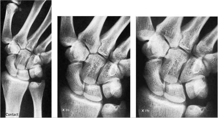
Macroradiography can also be used for imaging the carpal bones in cases of suspected fracture of scaphoid.
The commonest application of radiographic survey of the skeletal system is in suspected cases of non-accidental injury in children, when it is necessary to demonstrate the presence, multiplicity and age of any bone injury. The technique and imaging protocols required are described in detail in Chapter 14 (see p. 428).
In adults, multiple trauma, often from moving vehicle accidents, accounts for most situations where a skeletal survey is used. Reference has been made on page 471 to the Advanced Trauma Life Support (ATLS) imaging survey.
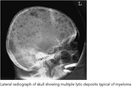
Another situation in which a skeletal survey may be useful in adults is the diagnosis and assessment of a patient with suspected myeloma, a malignant disease of the blood plasma cells. The diagnosis is usually made by detection of an abnormal immunoglobulin in the blood, but plain film radiographs are used in equivocal cases to confirm a diagnosis and to assist in monitoring the disease. Myeloma is unusual in that bony deposits of tumour do not usually elicit an osteoblastic reaction, and for this reason a radionuclide bone scan will often be negative.
Before the advent of modern radionuclide imaging, plain-film radiographic skeletal surveys were used as a primary means of diagnosing and assessing bony involvement in various pathological conditions, especially metastatic disease and some metabolic disorders.
Plain film radiography is now reserved for problem-solving when radionuclide scans require clarification, for example to determine whether a 'hot spot' is due to metastasis, degenerative disease, or some other condition such as Paget's disease. Modern biochemical tests have removed the need for skeletal surveys in the management of most metabolic and endocrine disorders, although radiography may be used to assess complications such as development of 'Brown tumours' in hyperparathyroidism or in detection of pathological fractures.
Since the development of disease-modifying drug regimens, serial radiography is increasingly used to monitor the progress and response to treatment of inflammatory arthropathies, particularly rheumatoid arthritis. This will normally be limited to the small joints of the hands and feet, but other areas may be imaged as clinically appropriate.
MRI offers the ability to image the soft tissues in addition to skeletal structures. For this reason, as well as its superior sensitivity and its ability to detect problems at multiple levels, it has largely replaced other imaging modalities in the assessment of suspected spinal cord compression.
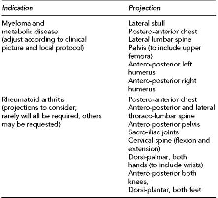
Whenever a skeletal survey is considered, the projections should be adapted to the clinical information required and local protocols. Guidance from the clinician and/or radiologist in charge is important in determining the correct projections.

Lateral radiograph of lumbar spine showing multiple areas of vertebral collapse, of varying age, due to myeloma. Excessive collimation has partially obscured the lower two lumbar vertebrae
Recommended projections

Antero-posterior radiograph of shoulder showing multiple lytic deposits of myeloma in the humerus, scapula, clavicle and ribs

Radionuclide bone scan showing diffusely increased skeletal uptake and absent renal uptake (superscan) in a patient with metastases from carcinoma of the prostate
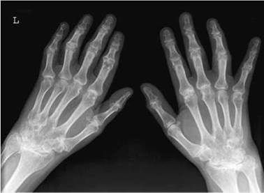
Dorsi-palmar radiograph of both hands and wrists in a patient with seronegative arthritis

Antero-posterior and lateral radiographs of the elbow in a patient with myeloma, showing multiple tumour deposits and a pathological supracondylar fracture of the humerus
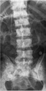
Antero-posterior radiograph of the lumbar spine in a patient with diffuse sclerotic metastases from carcinoma of the prostate
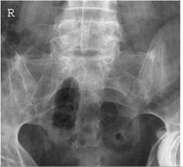
Postero-anterior radiograph of the same patient shown left, demonstrating fusion of the sacro-iliac joints sometimes seen in this condition
Introduction
Soft-tissue radiography is the term generally used for radiography of muscle, skin, and subcutaneous and glandular tissues without the use of contrast media. There is normally only a small differential attenuation between adjacent structures, which results in lower subject contrast. Fat, however has a lower density than other soft tissue and the attenuation coefficient results in a higher optical density on the radiograph. The fat shadow may, therefore, delineate adjacent soft tissue structures and is normally demonstrated in subcutaneous tissue, between faciae, muscles and tendons. In order to successfully demonstrate soft tissues, specifically when using conventional film/ screen technology, special attention must be given to:
• radiographic contrast: use of appropriate exposure technique, and reduction of scattered radiation;
• image sharpness: immobilization, small focal spot, film or film/ screen combination chosen according to exposure technique;
• avoidance of artefacts: non-screen technique or scrupulously cleaned screens, avoidance of dressings, and avoidance of folds in the skin or in the patient's gown.
Skin tumours such as subcutaneous cysts and warts may cause confusing opacities and should be noted on the X-ray request card along with any other unusual features that may mislead the radiologist.
Exposure technique
Several different exposure techniques may be used. They may be divided broadly into two categories: those employing a normal kVp for the area being examined and those employing a non-standard kVp.
Normal kVp
This category may be divided into three subcategories:
• Use of a normal technique for the part being examined when air shadows or fat pads may delineate abnormalities in adjacent soft tissue structures, e.g.:
- effusion in a synovial cavity causing a filling defect in a fat pad adjacent to a joint;
- enlarged adenoids causing a filling defect in the air contained in the nasopharynx.
• Use of two or more films or film/screen combinations to demonstrate both bony detail and soft tissue with one exposure, e.g.:
- facial bones, nasal bones and soft tissues of the face;
- calcification of tendons and bony detail of the shoulder joint.
• Use of a wedge filter, where the thicker part of the wedge attenuates the beam over the soft tissues, e.g.:
- cephalography to demonstrate bony detail of the skull and facial bones along with the soft-tissue outline of the face on one film;
- to see the soft tissue of the toes when exposing the whole foot.
Non-standard kVp
This category of exposure technique may also be divided into three subcategories: subnormal kVp, low kVp and high kVp.
Subnormal kVp
This term is used when the kVp employed in less than 45 kVp, which is the lowest useful kVp available on many X-ray units. Modified or special equipment is required that has an X-ray tube with reduced added and inherent filtration along with a small focal spot size. The use of such kVp increases differential attenuation of adjacent soft tissues and thus increases subject contrast. Radiographic contrast may be increased further by the use of a film or film/screen combination with a high average gradient, i.e. more than three. An example of the use of this technique is found in mammography.
Low kVp
This term is used when the kVp employed is 15-20 kVp less than normal for a similar projection of the area being examined. Bony detail is not demonstrated in this case. Examples of the use of this technique are calcifications in limbs, e.g. calcification of arteries or tendons, parasitic calcifications and superficial tumours, normally demonstrated in a profile projection of the area.
High kVp
This term is used when the kVp employed is 20 kVp or more than that normally used for a similar projection of the same area. The use of such kVp reduces the differential attenuation of soft tissues, decreasing subject contrast, and thus allowing a greater range of tissues to be demonstrated. An example of this is the greater visualization of the bowel wall in double contrast barium enema examinations. When used with CR, edge enhancement (enhancement of the boundaries of different tissues) offsets the reduced contrast.
Note
Digital imaging technology facilitates the application of 'windowing' the acquired image to visualize soft tissue areas even when normal kVps are employed.
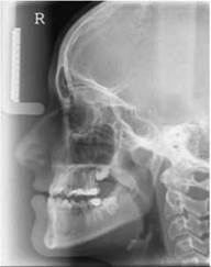
Example of a lateral cephalogram showing both skull bone and facial soft tissues on the one image
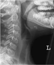
Lateral soft tissue image of the neck
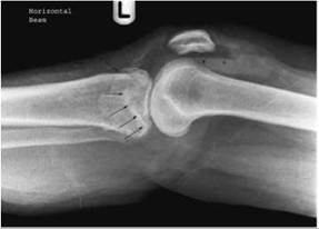
Horizontal beam lateral knee CR image windowed to show soft tissues showing depressed fracture of tibial plateau (arrows) and lipohaemarthrosis (arrowheads)

Image of traumatized ear Soft tissue image of tongue
Exposure technique
Choice of projection
To demonstrate soft-tissue lesions, the most suitable projections are those that will project the area under examination away from the adjacent bone. Normally the projections described in the appropriate chapters of this book will be used, but occasionally a profile projection will be required of the area under examination.
Lesions demonstrated by air
Soft-tissue lesions may be demonstrated by air in body cavities, e.g. enlarged adenoids encroach on the posterior nasopharyngeal air space demonstrated on a lateral projection of the neck. After adenoidectomy, there is no longer soft-tissue encroachment on the air space. A normal exposure technique for the part being examined is used in these cases.
Air in the soft tissue is known as surgical emphysema and may be caused by trauma, especially rib fracture or perforation of an abdominal viscous such as the rectum. A large area must be included on the radiograph; therefore, a high kVp should be used.
Lesions demonstrated by fat
Fat has a lower attenuation coefficient than other soft tissue and shows as a higher optical density on the radiograph. Effusion in a synovial cavity may cause a filling effect in a fat pad adjacent to a joint. Blood-lipid fluid levels may also be demonstrated when a horizontal central ray technique is used. It is, therefore, essential that the kVp used to demonstrate joints is sufficient to demonstrate both bone and soft-tissue structures.
Lipoma is a benign, well-defined fatty tumour that is more transradiant than adjacent tissues and therefore appears as a darker area on the radiograph. A normal exposure is used.
Calcifications in soft tissue
Calcifications in limbs, e.g. calcifications of arteries, tendons and ligaments, and parasitic calcifications, are usually best demonstrated by using a low kVp exposure technique. Calcifications in the trunk are demonstrated using a normal exposure technique.
Bone and adjacent soft tissues
In conditions such as rheumatoid arthritis, gout, myositis ossificans and osteomyelitis, there may be soft-tissue swelling and calcification. It is, therefore, essential that the kVp is sufficient to demonstrate both bone and soft-tissue structures.
Introduction
Forensic medicine is defined as the use of medical knowledge, especially pathology, to the purposes of the law, as in determining the cause of death.
Forensic radiography is the use of radiographic knowledge to aid in the implication of forensic medicine. The word 'forensic' comes from the Latin ‘forensic', meaning 'to the forum'. The forum was the basis of Roman law and was a place of public discussion and debate pertinent to the law.
Forensic anthropology is the application of the science of physical anthropology to the legal process.
Whilst radiography is necessary when dealing with individual victims, it is also used on a greater scale when associated with major tragedies such as train crashes and air disasters.
Imaging is also required in the identification of individuals whose remains may be badly decomposed or only skeletal. Such identification may be associated with war victims or civil atrocities with victims found in mass graves.
Classification of forensic radiography
Radiography of a cadaver is undertaken for several different medical purposes:
• fetal and neonatal;
• identification;
• cause of death.
All of these investigations are usually requested under the direction of the coroner, and the attending pathologist will request specific areas to be examined radiographically.
Post-mortem imaging may also be requested to identify any previous disease processes or trauma that the deceased has suffered and that may or may not have contributed to their death.
Another area of forensic radiography in either the live or deceased patient is in the assessment of non-accidental injury (NAI), usually in paediatric patients but also now in elderly patients.
For elderly abuse queries, the areas to be imaged will be identified by the pathologist. For paediatric abuse queries, the protocol authorized within the place of work must be used for either live or deceased patients.
The foremost pitfalls in the radiological diagnosis of abuse are suboptimal radiological imaging, radiographic underexposure or overexposure, and malposition.
A protocol will specify the projections required and also the high technical image quality needed to identify the fine changes and disruption of normal bone patterns.
Other specific areas to be imaged may also be requested by the pathologist to ascertain the maximum amount of information from the X-ray examination.
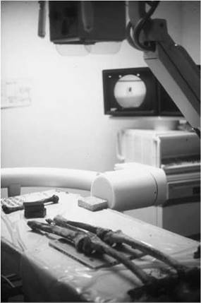
Radiography of lower limb skeleton
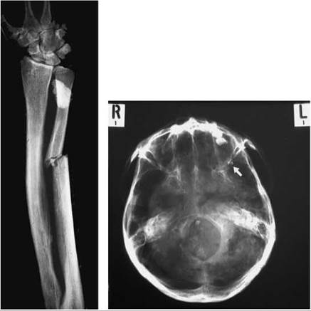
Fractured ulna Skull base projection
Anatomical terminology
There are few clinical words and terms that are used purely in this scenario. Anatomy references are generic, regardless of whether the patient is alive or post mortem.
Legal issues
The College of Radiographers stated in 1999: 'Forensic radiography refers to the application of medical knowledge in the collection of evidence to be used in a court of law.'
To ensure parity for all forensic examinations, certain guidelines and methods of recording evidence are necessary:
• All radiographs taken must be signed by the radiographer.
• Date and identification (ID) must be photographed on to the image.
• Number of images and all projections taken must be formally noted and signed by the radiographer and a witness.
• No copies of the original images.
Equipment and accessories
The X-ray equipment required for forensic radiography is variable and dependent on what is available and whether the imaging is to take place off site. It may include:
• mobile X-ray machine;
• dental radiographic equipment;
• fluoroscopy equipment;
• digital radiographic equipment;
• CT (on-site or mobile) equipment;
• MRI (on-site or mobile) equipment;
• film-processing facilities with darkroom.
If standard mobile X-ray machines are to be used, then cassettes, grids, film and processing equipment will also be required.
Cassette size and intensifying screen type are dependent on the area being examined.
Electricity and water supplies will also be required if working off site.
Using fluoroscopy or any other digital method of imaging also gives the option of digital storage of the images produced. Accessories required include:
• protective clothing, including gown/suit, gloves and mask;
• plastic bags to protect cassettes;
• cleaning materials;
• pads and sandbags;
• radio-opaque markers;
• stationery.
Local radiation rules
If forensic radiography is undertaken on site, i.e. on Trust property, then departmental local radiation rules with regard to radiation protection for all radiographic examinations must be adhered to.
Separate local rules will need to be drawn up when working in an emergency mortuary situation. These must include the identification of:
• the radiation protection supervisor (RPS);
• the radiation protection advisor (RPA).
The RPA is the radiographer's employer's (i.e. the Trust's) RPA.
• The definition of a 'controlled area' must be stated, including marking boundaries and erecting warning signs.
• The controlled area must be of at least a 2-m radius from the X-ray tube (vertical beam).
• All personnel within this area must wear protective equipment.
• Monitoring devices must be placed at the boundary of the controlled area.
• For horizontal-beam radiography, where possible the primary beam must be directed towards a primary shield and the controlled area extended to 6 m from the X-ray tube.
De-briefing
This process of assessing the effects of the trauma of undertaking forensic radiography in any situation is essential for the welfare and support of the professionals involved. The radiographers must be made aware of the signs and symptoms of stress, and strategies identified to help them cope with it.
A support mechanism must be provided for these professional volunteers and access to specialist support must be made available.
A de-briefing session after a major incident is standard procedure in the police force, and any radiographers involved in these incidents participate in these sessions.
Forensic radiography should be undertaken by volunteer radiographers whenever possible.
Dental radiography
The primary technique used in the identification of a cadaver is the comparison of dental records. This examination can be used regardless of the stage of decomposition or the post-mortem state of the cadaver.
An odontologist will examine the cadaver's dentition to record a plan. In addition to this visual and clinical assessment by the specialist, dental X-rays may also be requested.
The images produced can be evidential proof of cadaver identification when matched to previous dental records. Radiographic detail of the following will aid the odontologist in the final identification of a cadaver:
• fillings and dental intervention;
• root morphology;
• unerupted teeth;
• dental patterns;
• previous dental surgery.
Recommended dental projections
The odontologist may request several standard radiographic dental and facial projections. The primary projections taken to produce maximum information are:
• lower standard occlusals;
• upper standard occlusals;
• intra-oral radiographs;
• mandibular projections.
The radiographic technique for these projections can be found in the appropriate dental/facial sections of this book (see Section 10).
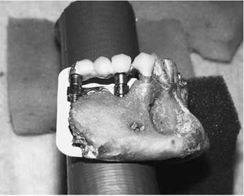
Imaging a section of the mandible
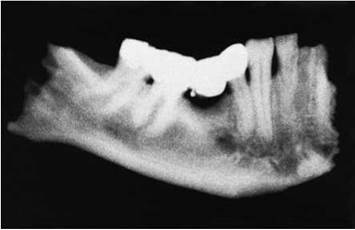
Radiograph of a fragment of mandible recovered from a plane crash. A gold bridge is shown with melting of gold solder due to the heat of the fire following the crash
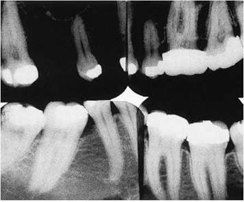
Post-mortem bitewing radiographs of teeth

Ante-mortem bitewing radiographs of teeth matching the post-mortem radiographs seen above
General radiography
Adaptation of technique
Several changes to normal radiographic technique for both dental and general radiography undertaken will be required.
The majority of forensic radiography is carried out distant from the imaging department and using mobile radiographic equipment. Forensic radiography will usually be undertaken in a mortuary, either permanent or temporary.
The physical state of the cadaver will determine the number of projections that will be taken and the techniques that can be used.
The cadaver may be contained (e.g. in a body bag); whilst this is advantageous with regard to health and safety and crossinfection, it does limit any changes to be made in positioning of the cadaver for X-ray examination.
Care must be taken to ensure that no sharp or dangerous objects are present in the body or body bag. The radiographer needs to be aware of these potential dangers of injury to himself/herself and others.
Thus, no protocol can be formalized for forensic imaging, as the examination is dependent on many variables.
Adaptations will be required to all standard radiographic techniques for each examination being undertaken.
Imaging may be undertaken using a selection of cassettes containing film/screens systems in order to provide full coverage of the body. Alternatively, imaging may be undertaken using a mobile C-arm fluoroscopic system enabling full screening of the body to identify specific abnormalities. Such equipment will incorporate an imaging recording system in order to record and catalogue forensic features.
When using such equipment to image a body bag, it is important that a scanning technique is adopted that allows for overlapping of areas of the body to ensure that no area of the body and body bag are left un-imaged. The C-arm should be moved in a set pattern. The use of floor markings will aid the radiographer to ensure overlapping of the image intensifier field.
When necessary, two plain-film projections at right-angles are taken of a specific area. This may be required to provide further information on the nature and extent of a sustained injury.
Images may also be required of sections of the body that have been removed by the pathologist for more detailed forensic examination.
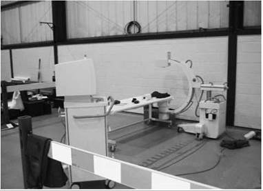
Distant mortuary set up with a mobile image intensifier system

Air crash victim with severe pelvic trauma
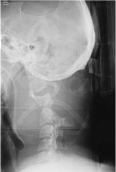
Motorcyclist with extensive neck trauma - note air in the oesophagus

Lateral skull showing a bullet trace

Self-inflicted injury using a nail gun at point blank range
Still born (15-40 weeks)
General comments
• A full skeletal survey is undertaken, at the request of the coroner for the pathologist.
• Identification is by referral card and is cross-checked with the identification bands on the limbs of the fetus.
• The technique normally employed is that of whole-body 'babygram' with both antero-posterior and lateral projections acquired.
• Dependent upon the gestational age of the fetus, additional fronto-occipital and lateral skull images are taken.
• Images are acquired using a 400-speed film/screen system in a standard cassette or using a CR/DDR system.
• Images are shown to a specialist radiologist.
• Further images may be requested dependent upon any abnormalities that are identified at the time of imaging.
Imaging technique
• As the health and safety of the staff is imperative, the procedure is easier if two radiographers perform the examination. This will reduce the risk of cross-injection and provide added personal protection.
• The X-ray room is prepared. The imaging cassette is covered in a polythene sheet, taking care that it remains smooth to exclude any crease artefacts being recorded on the image.
Antero-posterior 'babygram'
• The fetus is placed on the covered cassette in the supine position.
• The limbs are positioned antero-posterior where possible. It may be necessary to support these in place by using plastic strips taped down over the limbs or covered sandbags.
• The X-ray tube is centred and collimated to include all the relevant anatomy. (Specific techniques are detailed in Section 14.)
• Lead markers are placed into the collimated area.
• Exposure factors should be selected consistent with the size of the fetus.
Note
Normally, X-ray rooms used for this purpose have a detailed exposure chart (e.g. 25-week fetus: 56 kV, 1.4 mAs.)
Identification
The imaging cassette is marked immediately following exposure, ensuring that the correct information and orientation are on
the image, including date and identification number.

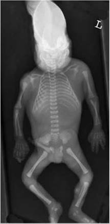
Examples of antero-posterior whole-body images of fetuses
Lateral 'babygram'
• The fetus is placed on the covered cassette in the lateral position. The cassette size is dependent upon the size of the fetus.
• The limbs are positioned lateral where possible. It may be necessary to support these in place by using plastic strips taped down over the limbs/covered sandbags or soft roll.
• The X-ray tube is centred and collimated to include all the relevant anatomy. (Specific techniques are detailed in Section 14.)
• Lead markers are placed into the collimated area. It may be necessary to mark individual limbs to ensure correct identification.
• Exposure factors should be selected consistent with the size of the fetus.
Note
Normally, X-ray rooms used for this purpose have a detailed
exposure chart (e.g. 25-week fetus: 56 kV, 1.4mAs.)
Identification
The imaging cassette is marked immediately following exposure, ensuring that the correct information is on the image,
including the date and patient identification number.
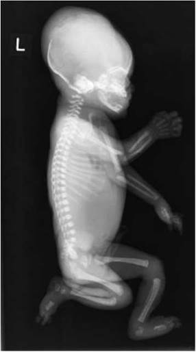

Examples of lateral whole-body images of fetuses
Still born (15-40 weeks): skull projections
Fronto-occipital
• The fetus is placed on the covered 18 X 24-cm cassette/ imaging plate in the supine position.
• The skull is normally flexed forward at presentation, but a covered 15-degree wedge may be placed under the shoulders to bring the orbito-meatal lie at right-angles to the cassette.
• Soft roll or covered pads are used to immobilize the skull and prevent rotation.
• The remainder of the technique is as described in Section 14.
Note
Normally, X-ray rooms used for this purpose have a detailed
exposure chart (e.g. 25-week fetus: 56 kV, 1.4mAs.)

Fronto-occipital skull image of a fetus
Lateral
• The fetus is turned into the lateral position, with the head resting on the covered 18 X 24-cm cassette/imaging plate.
• A soft roll or covered pad may be placed under the face to bring it parallel with the table and cassette.
• The remainder of the technique is as described in Section 14.
Note
Normally, X-ray rooms used for this purpose have a detailed exposure chart (e.g. 25-week fetus: 56 kV, 1.4 mAs.). An alternative technique is to use a horizontal beam lateral. This may be required, dependent upon the presentation of the fetus.
Identification
The imaging cassette is marked immediately following exposure, ensuring that the correct orientation and information are on the image, including the date and patient ID number.
Post-procedure
• The X-ray equipment and room are cleaned according to hospital protocol.
• The referral card and images (where appropriate) are presented to the radiologist for report.

Lateral skull image of a fetus
Skeletal survey - out of hours
Skeletal survey protocols for cot death and other such fatalities, as well as non-accidental injury investigations in children, are discussed in detail in Section 14 (see pp. 428-431). However, in the 'out of hours' situation, a protocol should be adopted similar to the one described below, which will assist as a reminder and guide for all those involved in undertaking this task. It is often the case that such requests are made out so infrequently that such a protocol will be helpful in determining the roles and responsibilities of every member of the team. Included on the page are some images for the standard radiography series.
Example protocol
• The accident and emergency (A&E) sister/mortuary technician to liaise with the on-call radiographer.
• All surveys should be performed in the X-ray department.
• A record is made of the names of all staff involved in the imaging procedure and attendant during the procedure.
• A decision is made on the time to perform the survey. (Note that this should be during normal working hours where possible.)
• The lead paediatric radiologist must be informed when the survey is to be performed on a child.
• The on-call radiologist must be informed when the procedure is to be performed on an adult.
• The entire examination must be witnessed. This may be the sister from A&E, a police officer or a coroner officer.
• Witnesses must be present throughout the procedure and must not leave the subject unattended at any time.
• The subject must be identified correctly, and all images must be labelled correctly with name and date. Side-markers should be present on all projections at the time of the examination.
• At the end of the procedure, hard copies of the images with a radiologist report should be handed over to the coroner's officer.
• In extreme circumstances, i.e. when the coroner requests to move the body before a radiologist arrives, it is important to ensure that the referral card is given to the appropriate radiologist for them to issue a report later, as follows:
Compiled by:
Name of authorizer:
Date of protocol:
Review date:

Antero-posterior skull on a 1-year-old child

Lateral skull on the same child (above) showing a fracture in the parietal region

Anterior oblique right ribs
Further reading
Merten DF, Carpenter BLM (1990). Radiologic imaging of inflicted injury in the child abuse syndrome. Pediatric Clinics of North America, 37, 815-37.
College of Radiographers (1999). Guidance for the Provision of Forensic Radiography Services. London, College of Radiographers.
Whitley AS, Alsop CW, Moore AD (1999). Clarke’s Special Procedures in Diagnostic Imaging. London, Butterworth Heinemann, p. 380.