
Introduction
Mammography is the radiographic examination of the breast tissue (soft tissue radiography). To visualize normal structures and pathology within the breast, it is essential that sharpness, contrast and resolution are maximized. This optimizes, in the image, the relatively small differences in the absorption characteristics of the structures comprising the breast. A low kVp value, typically 28 kVp, is used. Radiation dose must be minimized due to the radio-sensitivity of breast tissue.
Mammography is carried out on both symptomatic women with a known history or suspected abnormality of the breast and as a screening procedure in well, asymptomatic woman. Consistency of radiographic technique and image quality is essential, particularly in screening mammography, where comparison with former films is often essential. Whilst other techniques such as magnetic resonance imaging (MRI) and ultrasound have a role in breast imaging, mammography is undertaken to image the breast most commonly and is hence considered in detail in this chapter.
Recommended projections
Examination is performed by means of the following projections:
|
Basic |
• 45-degree medio-lateral oblique |
|
projections |
(Lundgren) |
|
• Craniocaudal |
|
|
Supplementary |
• Extended cranio-caudal laterally |
|
projections |
rotated |
|
• Extended cranio-caudal medially rotated |
|
|
• Extended cranio-caudal |
|
|
• Medio-lateral |
|
|
• Latero-medial |
|
|
• Axillary tail |
|
|
• Localized compression/paddle |
|
|
• Magnified (full-field/paddle) projections |
Author's note regarding projections
All projections are described on breasts of an average size, with the woman standing, unless otherwise stated. The projections can, however, be achieved with the woman seated, even in a wheelchair. The word 'woman' is used to describe those undergoing the examination as not all attendees for mammography will be patients. It is acknowledged that mammography is also performed on men, albeit rarely.
The exception to the use of the word 'woman' is in the heading 'Position of patient and cassette', which is retained for consistency with the rest of the book.
The heading 'Direction and centring of the X-ray beam' has been omitted from all descriptions of the projections. The linked nature of the tube and image-recording mechanism make the direction and centring of the X-ray beam implicit in the description of the position of the patient and cassette.
The two basic projections are done both for asymptomatic and for symptomatic women. Supplementary projections may be used if these projections fail to demonstrate a clinically detected lesion, or to demonstrate a lesion more clearly.

Positioning terminology
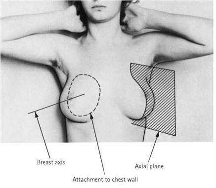

Despite the great individual variation in the external form of the breast, the approximately circular attachment to the chest wall is constant. Vertically the attachment extends from the second to the sixth rib, and at the level of the fourth costal cartilage it extends transversely from the side of the sternum to the mid-axillary line.
A line drawn from the centre of the circle to the nipple can be termed the breast axis. Two planes of importance in radiographic positioning pass through the breast axis. The axial plane divides the breast into inner and outer portions; the transverse plane lies at right-angles to the vertical axial plane, intersecting it along the breast axis. The breast is thus divided into quadrants, termed upper outer, lower outer, lower inner and upper inner, respectively. In the normal erect resting position, the axial plane makes an angle of 20-30 degrees with the sagittal plane of the body, and the transverse plane makes an angle of 30-50 degrees with the horizontal.
A prolongation into the axilla of the supero-lateral portion of the breast along the lower border of pectoralis major is called the axillary tail. The retromammary space lies behind the glandular tissue and should be visible (at least in part) on a correctly positioned mammogram. Microscopically, the breast consists of 15-20 lobes, supported by a stroma of fibrous tissue, which contains a variable quantity of fat. Each lobe has a main duct, opening in the nipple. Deeply, the ducts branch within the breast to drain lobules. Each lobule consists of a cluster of small ductules, into which the glandular epithelium cells pass their secretions. Lobules are demonstrated radiographically as fine, nodular opacities, individually measuring 12 mm in diameter but usually superimposed to give a more or less homogeneous opacity.
With progressive involution, the lobules successively shrink and become invisible. Involution commences in the subcutaneous and retromammary regions, then progresses sequentially through the lower inner quadrant, the upper inner and lower outer quadrants, and finally the upper outer quadrant.

Female breast anatomy
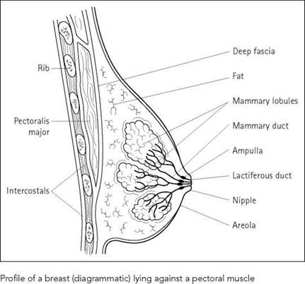
The breast (mammary gland) is one of the accessory organs of the female reproductive system. The adult breasts comprise two rounded eminences situated on the anterior and lateral walls of the chest, lying superficially to the pectoral muscles and separated from them by areolar tissue and fascia. They extend from the second to the sixth ribs and from the lateral border of the sternum to the mid-axillary line. The supero-lateral part is prolonged upwards and laterally towards the axilla to form the axillary tail. The nipple is a conical projection just below the centre of the breast, corresponding approximately to the fourth/fifth intercostal space.
The breast is composed of glandular, fibrous and fatty tissue. Its size, shape and consistency vary significantly, depending on the patient's size, shape and age. Each breast consists of 15-20 lobes, each of which is divided into several lobules. The lobules comprise large numbers of secretory alveoli, which drain into a single lactiferous duct for each lobe, before converging towards the nipple into the ampullae before opening onto the surface.
The blood supply is derived from branches of the axillary, intercostal and internal mammary arteries. The lymph drainage is shown diagrammatically opposite.
With increasing age, and especially after the menopause, the glandular elements of the breast become less prominent and tend to be replaced by adipose tissue (fat). Fat attenuates the beam less than glandular breast tissue; as a result, fatty breast is darker. Significant disease (which tends to be dense and produce high attenuation or bright areas on the film) is detected more easily. Younger breast tissue is denser (whiter), and the sensitivity of mammography in patients under 50 years of age is thus reduced. The younger breast is also more sensitive to the adverse effects of ionizing radiation, so ultrasound is often used as the first-line investigation in younger patients, especially under 35 years of age.


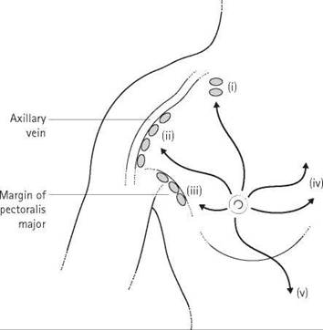
Schematic diagram of the lymph drainage of the breast: (i) apical axillary nodes; (ii) lateral axillary nodes; (iii) pectoral nodes; (iv) to anterior mediastinal nodes; (v) to abdominal wall
X-ray equipment features
A mammography system comprises:
• a high-voltage generator;
• X-ray tube;
• tube filtration;
• compression device;
• reciprocating anti-scatter grid;
• image-recording system;
• automatic exposure control (AEC) system.
Consistently high equipment performance is required to ensure that any small changes that may indicate breast cancer are detected.
• The generator must be able to maintain a very accurate kVp in the range of 25-35kVp. High tube currents of about 100 mA are used for mammography and about 25 mA for magnification mammography using fine focus. The generators are commonly constant potential with a low kVp ripple.
• The X-ray tube has certain special design features, including a beryllium window, which attenuates less of the low-energy beam than glass, a small focus (^0.06 mm) and a molybdenum target.
• The tube filter is 0.03 mm of molybdenum or 0.5 mm aluminium equivalent to absorb X-rays below the optimum kVp range. Some equipment has dual filtration capabilities, e.g. 0.03 mm molybdenum for routine use and 0.025 mm rhodium to provide dose reduction and good image quality in denser breasts.
• Breast compression should be applied only to a level that the woman can tolerate and not above 200 Newtons. Some equipment has automatic compression available, which optimizes the compression based on the characteristics of the individual breast, to achieve uniform tautness.
• The grid has a line spacing of 35 lines/cm and a grid factor of 5:1. A specially designed moving grid is usually needed, despite its dose implications. The standard grid is a 5:1 linear, moving grid. The necessity for a grid depends on the choice of anode material, the total filtration, the tube voltage, and the density and thickness of the breast. An image of satisfactory quality at an acceptable level of average entrance surface dose is essential. For more dense and/or thicker breasts (>6cm compressed), a tungsten anode, aluminium or other special tube filtration, e.g. rhodium, higher tube voltages and an anti-scatter moving grid are preferable. For thinner breasts (<4 cm), the use of an anti-scatter grid may not always be necessary. In practice, however, a grid is usually used. A high transmission cellular grid has recently been developed. This is essentially a cross- hatched grid that will reduce scatter in all directions, not only in a direction perpendicular to the radio-opaque grid slats.
• The image receptor system is described in the image acquisition section.
General features
Ease of manoeuverability and lightness of the mammography unit are essential to facilitate its use. These features are important both for the operator and for the women examined. A narrow tube head is advantageous to the operator for positioning and to the woman for comfort. Clearly, the design must ensure that there are no areas of the unit that could damage the woman due to sharp edges or generated heat. Handles are provided on the unit to support women who are unsteady or frail. Certain units incorporate face shields so that the woman's head cannot get into the beam path. Motorized isocentric rotation of the swivel arm and Bucky is available, ensuring that the equipment remains at a constant height throughout rotation.
Some modern equipment is modular, allowing upgrading as new technology becomes available, e.g. upgrading from digital spot mammography to a full breast digital imaging system.
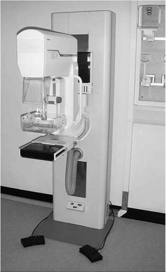
Image acquisition
Mammography can be performed by a variety of imaging techniques. The clinically and technically taxing nature of breast X-ray imaging has caused it to remain one of the few essential film-based radiological imaging techniques. Nevertheless, mammography is benefiting greatly from the incorporation of digital imaging technology to ensure optimum presentation of all clinical images, to allow the use of computer-aided diagnosis, telemammography, digital image management and archiving. Some digital image acquisition systems have dual modes available according to the imaging requirements, e.g. high-contrast images or images with high spatial resolution can be produced.
Image recording systems available include:
• single emulsion film, single intensifying screen combination;
• digital acquisition using photo-stimulable phosphor computed radiography (CR);
• digital acquisition using selenium detectors.
The choice of imaging system will depend on availability and departmental protocols. However the image is acquired, European Commission (EC) standards state that the system must allow visualization of:
Round details 3 mm or more
Micro-calcifications 0.2mm or more
The Pritchard Report 1987 stated certain parameters for image quality and their acceptable values. These were derived from the use of a Leeds test object resolution (TOR) (max) mammography test object.
The minimum acceptable values are:
High-contrast spatial resolution 8.9 line pairs/mm
Low-contrast spatial resolution 3.2 line pairs/mm
Large area, low-contrast detectability 7 details (6 mm detail) Small-detail contrast detectability 7 details (0.5, 0.25 detail)
Exposure factors
The kVp output of mammographic machines is adjustable between 25 and 35 kVp. The tube current is kept as high as possible to minimize exposure times and should be at least 100 mA, with the 0.3mm2 focus commonly used for routine mammography. EC standards state that the exposure time should be less than two seconds and the focal spot 0.6 mm2 or less. A 0.3-mm2 focal spot is used routinely to reduce geometric unsharpness. A 0.1-mm2 focal spot is used for magnified projections. An AEC is essential. The detector for this must be moveable so that it can be positioned behind the most dense part of the breast, which typically lies 2 cm behind the nipple. This allows a range of breast sizes to be imaged satisfactorily. The position of the detector must be marked so that the radiographer can locate it and move it between 2 and 15 cm from the chest-wall edge of the breast- support table, as appropriate, depending on the individual being examined. Typically, the AEC can be preset at (at least) two levels to allow the use of different film/screen combinations. The AEC should also allow the radiographer to alter the density levels that result, to take account of fluctuations caused by changes in processing conditions. A moving grid is essential in most breasts for good-quality images, despite its dose implications. In thinner breasts of less than 4 cm compressed, EC standards state that such a grid is not essential. The film/screen combination, if this is the recording system used, must be a dedicated high-resolution film/screen combination, with dedicated processing to comply with EC standards, and the focus-to- film distance (FFD) must be 60 cm or more. The imaging system must allow visualization of round details of diameter 3 mm or more and micro-calcifications of 0.2 mm or more. Some equipment allows a selection of exposure modes. In the manual mode, the radiographer selects all exposure parameters. There are also automatic exposure modes, e.g. auto-time, auto-kVp and auto-filter modes.
Film identification
Films are marked with an anatomical marker identifying the breast (left or right) and a projection marker. These two markers are often incorporated into one. Film markers are placed well away from the breast tissue, on the axillary side of the film. This is an international convention, which assists orientation.
Imaging parameters
Listed in the tables below are the recent EC image criteria in which it is acknowledged that fulfilment of the criteria may require more than one projection.
Diagnostic requirements
Image criteria
Visually sharp reproduction of the whole glandular breast Visually sharp reproduction of the cutis and subcutis Nipple should be parallel to the film
Criteria for good imaging performance
|
Important image details |
|
|
Round details |
3 mm diameter |
|
Micro-calcifications |
0.2 mm diameter |
|
Entrance surface dose |
|
|
for standard-sized patient, |
|
|
4.5 cm compressed breast, |
|
|
with anti-scatter grid |
7 mGy |
Example of good radiographic
technique
|
Radiographic device |
Specially dedicated equipment. Anode material molybdenum |
|
Focal spot size |
s0.6mm |
|
Total filtration |
0.03 mm molybdenum or 0.5 mm aluminium equivalent |
|
Anti-scatter grid |
Specially designed moving grid may be necessary |
|
Film/screen |
Dedicated high-resolution film/screen |
|
combination |
combination with dedicated processing |
|
FFD |
^60 cm |
|
Radiography voltage |
25-35 kV |
|
Automatic exposure |
Chamber selected, specially |
|
control |
positioned |
|
Exposure time |
<2 s |
|
Breast compression |
Should be applied to a level that the woman can tolerate |
FFD, focus-to-film distance
Processing
Whilst digital imaging will record breast mammography in the future, and is indeed already available on some units, film/screen mammography is still commonly performed. Dedicated processing is required to comply with EC standards. This requires an adequate throughput of films daily to ensure processor stability. Single emulsion films with an anti-halation backing, as used almost exclusively in mammography, are particularly sensitive to changes in processing conditions. The emulsion of such films is made particularly sensitive to green light from the visible spectrum, and is matched to the light emission from the single fluorescent screen in the mammography cassette. Whilst the film used will vary due to radiologist choice, it will fulfil the criteria of having high contrast and high speed, to maximize the low inherent contrast of the radiosensitive breast.
Whilst the processing time was typically extended by 2-3.5 minutes, with a development time of 35-40 seconds at a temperature of 32-35°C, this is no longer the case. Film/screen technology is available, e.g. Kodak MIN R 2000 film with 2000 intensifying screen, that reduces the processing time to 90 seconds.
Further reductions in processing time are in advanced development, e.g. Agfa Mammoray HT film with Detail R Mammoray screens. This combination has a processing time of 45 seconds.
Images processed via these shorter cycles are of high contrast and resolution, with low noise and low dose. Processing time reduction increases work throughout. It is especially valuable in women undergoing stereotactic fine-needle aspiration (FNA) or breast localization markers before surgery, as the time in the machine in an uncomfortable position will be reduced greatly.
Processing parameters must be closely controlled and monitored, hence a quality control programme that is adhered to is essential. The reference and tolerance values of key parameters are established using sensitometric strips with the processor working at its normal working temperature. Subsequently, these parameters - base plus fog, speed index, contrast, maximum density - are recorded and monitored against these reference values, using a processor control chart. It is essential that the same steps on the sensitometric strips are always used for these measurements. If the base plus fog value, which should be less than 0.20 optical density (OD), and is typically 0.17 OD, varies more than plus or minus 0.03 OD, then action must be taken. The limits of acceptability for the speed index and the contrast are both plus or minus 0.10 OD. The minimum acceptable level for the maximum density is 3.6 OD. If variations outside the tolerance levels exist, then the test is repeated. If this yields similar results, then action is necessary and no mammograms should be processed until the processor returns to stability.
The processor control chart should also have recorded on it when a new box of films is used, to ensure that only the processor, and not the whole imaging system, is monitored. The dates when processing chemicals have been changed should also be recorded on the chart.
The processor should be monitored before and after servicing, and the date of servicing should be recorded. Replenishment rates, processor cycle time, developer temperature, silver recovery and residual spent reagents will also be monitored. Adequate replenishment is essential, and a higher replenishment rate than normal is needed. Inadequate replenishment is often the cause of poor mammographic quality. It leads to reduction in image contrast and film blackening. It is identified by a reduction in the speed index.
The processor should be monitored on a daily basis. This will allow any trends that are developing to be rectified before the system exceeds tolerance values.
Computer software packages that incorporate quality-control and effluent management systems are available.
Radiation protection
Absorbed doses are high in mammography due to the low kVp necessary to maximize the small differences in attenuation between tissues in the breast. A considerable proportion of the X-ray spectrum will, at the kVp used, not contribute to image formation but will increase breast dose. The breast is one of the most radio-sensitive tissues in the body. Careful technique is essential to avoid the need for repeat projections. Gonad protection, e.g. a lead-rubber apron, should be used, particularly in young women and in projections where the primary beam is directed towards the gonads, e.g. the cranio-caudal projection. Selection of the X-ray tube target material and the filtration used is important in dose reduction. The aim is to produce optimum image contrast but minimum dose. With careful choice of target material and filtration, the majority of the radiation that would contribute only to dose, and not to image formation, can be removed. This is done by using the characteristic radiation of a target material as close to that ideally required, giving an image of good contrast with low dose. This radiation is then filtered using a material whose absorption spectrum has a K-edge positioned such that it will filter out as much of the unwanted radiation as possible whilst leaving as much of the image-forming radiation as possible.
In practice, the target material required by the EC standards is molybdenum. This must be incorporated into specially dedicated equipment. The molybdenum target produces a very narrow band of low-energy radiation, particularly when used with a 0.03-mm molybdenum filter. This gives high-contrast films but means a relatively high radiation dose to the woman. In some units, it is possible to change the molybdenum filter to a 0.5-mm aluminium equivalent filter. The beam then simulates that produced by a tungsten target. A tungsten target with a 3-mm aluminium filter gives a narrow beam spectrum but at higher energy levels than from a molybdenum target. Contrast is reduced but radiation dose is lower than with a molybdenum target. Another advantage is that penetration of dense breasts is better. Other filtration material, e.g. rhodium, is available in some equipment for dense breasts.
It must be appreciated that the choice of anode material, total filtration, tube voltage and the use of a moving grid required to produce optimal image quality at an acceptable level of average entrance skin dose (7 mGy for a standard-sized woman, 4.5 cm compressed breast, with anti-scatter grid - EC standards) will depend substantially on the density and thickness of the breast examined. For denser and/or thicker breasts (>6 cm compressed), a tungsten anode, aluminium or other special filtration, higher tube voltages and an anti-scatter grid may be preferable; for thinner breasts (<4 cm), the use of an anti-scatter grid may not be necessary.
The compression device, a Perspex plate, which can be positioned manually but is more commonly motor-driven, has a role in radiation protection as it reduces dose because exposure factors are reduced. Additionally, it maintains close object-to-film contact, thus reducing geometric unsharpness and reducing movement unsharpness. It improves contrast by reducing the production of scattered radiation, flattens out tissues resulting in a film of even density that will demonstrate both anterior and posterior parts of the breast, and spreads out intra-mammary structures, allowing them to be visualized more easily.
Quality assurance
This is the application of techniques to ensure that a system or individual is performing at an optimal level. Quality control contributes to quality assurance by ensuring that pieces of equipment, e.g. the processor, are performing at optimal levels.
The Forrest Report 1986 recognized the importance of quality assurance in mammography, where the accuracy of diagnosis is very dependent on the image quality. Furthermore, consistency of standards was recognized to be essential, as subsequent screening examinations would use images from previous screening rounds for comparative purposes during mammography reporting. The Forrest Report 1986 recommended that a report regarding quality assurance should be commissioned. This resulted in the Pritchard Report 1987, which stated that 'the adoption of quality assurance system was crucial to the success of the introduction of breast screening in the UK'. The report gave guidelines on the establishment of a quality assurance system. Clearly, the performance of the service as a whole is dependent on all its integral parts, and no quality assurance initiative should be seen in isolation, even though the performance of each part of the system is measured against a specific stated objective. Parameters that were identified in the Pritchard Report 1987 for assessment were: equipment specification and performance, film/screen combination and cassettes, film processing, image quality, dose to the woman examined, and personnel performance.
The Pritchard Report provided detailed guidance on outcome objectives and standards, process objectives, quality assurance manuals, management of quality assurance, equipment procurement, testing and maintenance, training and performance of staff.
The guidance provided by the Pritchard Report 1987 on each parameter to be monitored was detailed. For example, it required radiographic performance to be monitored, such that 97% of examinations performed had to be diagnostic and less than 3% of women should need a repeat examination due to technical reasons.
Subsequent to this, the UK Mammography Trainers Group, with the support of the College of Radiographers (CoR), devised a way of evaluating radiographer performance via evaluation of the quality of the medio-lateral oblique mammograms. This method is used both for the accreditation of radiographers through the CoR's Certificate of Competence in Mammography and for long-term performance monitoring. Postgraduate courses incorporating this
Certificate of Competence are now available at several universities. In order to address the Pritchard Report and ensure that all women, irrespective of location, are assured of a high standard of service, a centrally monitored, formally organized quality assurance (QA) exists within the NHS Breast Screening Programme in the UK. In essence, at national level there is a specialist coordinating committee, consisting of all regional QA radiographers and regional representatives for each associated profession, e.g. physicists. Meetings are held in association with the relevant professional bodies, and they identify objectives and set standards. This committee reviews performance of the whole programme and the input of their professional elements down to regional level. At regional level, there is a regional QA manager, who chairs a committee consisting of a member of each of the professions that form the multidisciplinary breast-screening team. This committee institutes QA procedures and monitors regional performance. It considers details of performance down to unit level. This committee organizes multidisciplinary visits to units to discuss quality on an informal basis. Within each unit, a QA manager exists, commonly a radiographer whose role is to institute internal QA procedures and to ensure participation in external QA. Considering QA issues in the unit itself requires great tact, particularly with respect to assessment of the performance of individuals.
The NHS Breast Screening Programme publishes a series of booklets explaining the QA procedures pertinent to each profession. The QA programme has been so successful that similar measures have been extended into the Cervical Cytology Programme. EC standards were issued recently giving guidelines for QA in mammography and have been referred to above.
Overview of the UK Breast Screening Service
Breast cancer is the commonest form of cancer in the UK, affecting one in 12 women. As the incidence of and mortality from breast cancer in the UK were the highest in the world, in 1985 the government commissioned a report to consider how this serious problem could be addressed. The Forrest Report 1986 recommended that all females between the age of 50 and 64 years should be screened three-yearly. This led to the setting-up of the Breast Screening Service nationally. Screening mammography was advocated as the preferred method to promote early detection of breast cancer. As the cause of breast cancer was unknown, attempts at its prevention seemed futile. However, it had been recognized for some years that if cancers were detected at a time when they
were too small to be clinically detected and early treatment initiated, then prognosis improved.
Forrest predicted that, with screening, mortality could be reduced by 30%. The age group of 50-64 years was selected because in younger women the disease was less prevalent, and if it occurred it was thought to be more malignant and spread more rapidly. Younger breasts also contain more glandular tissue, making visualization of suspicious areas, e.g. micro-calcifications, more difficult. Previous trials had, however, shown screening of women over 50 years of age to be efficacious.
The screening interval was set at three years as a balance between letting as few as possible interval cancers escape detection and the cost, dose, etc. associated with more frequent screening. The working party in the Forrest Report acknowledged that the screening interval should be subject to amendment when the optimum screening interval was established.
Asymptomatic women attending for screening mammography initially had only the medio-lateral oblique projection of each breast taken. Many centres, however, also performed the cranio- caudal projection. Both a cranio-caudal and a medio-lateral oblique projection of both breasts at the prevalent screen became mandatory from the summer of 1995, to increase accuracy of breast cancer detection. At incident screening, normally only a medio-lateral oblique projection of both breasts is undertaken.
Forrest's other conclusions were that each screening service should have access to a skilled multidisciplinary team of radiographers, radiologists, clinicians, pathologists, breast-care nurses and surgeons. Each basic screening unit should serve a population of 41 500 women, and the requirement for units throughout England and Wales would be 120 centres.
The multidisciplinary team should take referrals from one to three basic screening units. The need for rigorous quality control to maintain the highest service standards was acknowledged.
Women with negative mammographic examinations were to be recalled in three years. In women where further projections were necessary as a result of a positive or equivocal result, the women would be asked to attend the assessment centre for additional projections, e.g. repeat mammography, magnified or paddle projections, ultrasound and/or FNA. This was to establish whether a lesion seen on initial mammography existed and, if so, whether it was benign or malignant. If it was established in this process that no significant abnormality existed, then the woman would be returned to the three-yearly screening recall. Her treatment otherwise would depend on the nature of the abnormality and the policy of the medical team in charge.
Screening is also available on demand to women over 65 years of age, and routine screening is being extended to age 70 years.
General comments
Similar considerations apply to most projections in mammography and they will therefore be considered here in one section. Mammographie changes of disease are often very subtle so that fastidious attention to technique is necessary at all stages of the process from image acquisition, through processing to interpretation.
Small artefacts, slight unsharpness of any cause, and any defect of technique may lead to serious errors of omission or interpretation.
Movement unsharpness may result from discomfort due to compression of the breast and should be assessed when checking the films. The major role of mammography is detection of malignant disease, which may occur in any area of breast tissue, so that full coverage of the breast is essential.
Images are viewed back to back, so that the corresponding projections are facing away from each other. Correct and clear marking of the side and projection make reading much easier, and the name details should always be clearly visible.
Emulsion pick-off artefact is usually obvious as such, but large amounts may mask micro-calcifications. Talc or aluminium in deodorants may produce small densities in the axilla that may be mistaken for, or mask, micro-calcifications. (Density in this context means area of dense breast tissue, which will produce a lighter area on the film.) Skin lesions may be visible as small, often well-demarcated masses and could therefore be mistaken for breast disease, so it is helpful for the radiographer to mark the position of any such abnormalities. The senile seborrhoeic wart is one common such lesion, though this may have a characteristic appearance. Skin folds produce dark lines, the cause of which is usually obvious, but they may be confusing, especially if subtle, and are to be avoided.
Composite or summation shadows are artefacts due to superimposition of two or more normal structures, or areas of glandular tissue, which produce an appearance simulating pathology. These can often be resolved by the use of further projections, in particular the spot compression view. Magnification projections are more useful for assessment of genuine lesions by giving more detail of the surface of a mass or more detailed images of calcifications.

Seborrhoeic wart in inner part of breast (lower part of image). Compare with the appearance of a carcinoma in the outer part of the breast (upper half of image)

Skin fold appears as low density line across breast
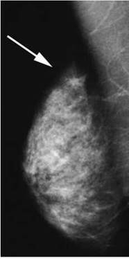
Composite artefact right axillary tail (confirmed by compression view and ultrasound)

Large ill-defined mass in elderly patient, highly suspicious of carcinoma
Lesion characteristics
Four main types of lesion are visible mammographically, namely masses, calcifications, architectural distortion and density, each of which is assessed according to a variety of features:
Masses
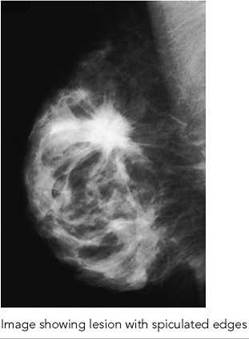
Masses are assessed by shape, margin and density. The shape may be round, oval, irregular or lobulated, and the margin (or surface) may be smooth, obscured (by surrounding tissue), indistinct or spiculated. Any of these may be hyper-, iso- or hypodense. Benign lesions tend to be round or oval and well-defined, whereas malignancies tend to be irregular in shape and outline and are often hyperdense. A low-density lesion suggests fat and is usually benign, e.g. oil cyst, lipoma, galactocoele. Lymph nodes often have a distinct appearance due to the fatty centre or hilum.
Calcifications
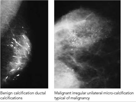
Calcifications vary in size, shape, number, grouping and orientation. There are many typically benign forms of calcification, such as dermal, vascular and popcorn calcifications. Milk of calcium is amorphous calcification in microcysts and has a characteristic teacup shape on the oblique projection. Many types of rod- and ring-like calcifications are also benign. Malignant calcifications are often grouped, linear or branching and irregular in size, shape and separation. New calcifications are suspicious, e.g. those appearing since the prevalent screening round, although new benign calcifications do appear. A significant number of calcifications are indeterminate, requiring further assessment.

Spiculated mass typical of carcinoma, with added diagnostic feature of micro-calcification
Architectural distortion
Architectural distortion is a feature of many carcinomas. It also occurs with benign conditions, such as sclerosing adenosis, radial scar and fat necrosis. In most of these cases, it can be proven benign only by histology. Surgical scarring causes linear distortion, which may be remarkably subtle with modern surgical technique; if gross, it will mask early features of recurrent disease.
Focal increased density
Focal increased density may be a sign of malignancy, but it has low specificity unless combined with other features. Breast density may be asymmetrical, reflecting previous surgical resection of the less dense breast or more rapid involution of the less dense breast as part of normal ageing. Benign disease may also cause asymmetric increased density, but focal density is regarded with suspicion.
Other features
Other features may be present, such as skin thickening, skin retraction, nipple retraction and trabecular thickening. These are assessed with the main features outlined above and in light of the clinical picture.
Lesion diagnosis
Some lesions are obviously benign or malignant. For example, a dense, spiculated mass with surrounding distortion, skin thickening and clustered, irregular micro-calcifications in a 70-year-old is almost certainly malignant, whereas a smooth, oval, well-defined isodense mass with popcorn calcification in a 35-year-old is most likely to be a fibroadenoma.
Typical lymph nodes have a fatty centre and hilum, oil cysts are well-defined and of fatty density, and duct ectasia may produce typical coarse ductal rod- or tube-like calcifications.
Many abnormalities, however, do not show diagnostic features and require further assessment by ultrasound and/or biopsy. Simple cysts are very common and appear as round, well-defined masses or clusters of masses, but there are no mammographic signs that are absolutely diagnostic of a cyst, so ultrasound or aspiration is usually required for diagnosis.
Some lesions are notoriously difficult to diagnose and closely mimic malignancy. One such is radial scar, which produces a spiculated area, often with an apparent small central mass. These are surgically removed, as even core biopsy does not exclude fibrosis next to a scar. Fat necrosis may produce all the features of malignancy and even at histology can be difficult to diagnose.

Axillary lymph nodes on mammogram. Left image shows normal node with a fatty centre. Right image shows same node later replaced by tumour
Therapy-related changes
Surgical scarring varies from a subtle isodense line at the site of earlier operation to a large, irregular, dense, spiculated area with marked surrounding distortion and skin change. In the latter case, detection of recurrent disease is more difficult and comparison with previous films is very helpful. For this reason, early follow-up films after wide local excision are often performed.
Radiotherapy produces an increased density of the breast, with diffuse trabecular thickening and often visible skin changes. Similar changes in a patient with carcinoma who has not had radiotherapy suggest lymphangitis of the breast.
Breast implants are very dense and obscure much tissue normally, but use of the Eklund technique allows adequate assessment in most cases. If this is not successful or cannot be achieved, then ultrasound and MRI are useful alternatives, depending on the clinical problem.
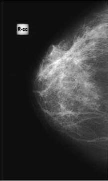
Mammogram appearance consistent with radial scar

Other techniques
Mammography may be supplemented by a variety of alternative imaging techniques, and in some cases these are used instead. These modalities are covered more exhaustively in Chapter 11 of Clark’s Special Procedures in Diagnostic Imaging (Whitley et al. (1999). London: Butterworth-Heinemann).
Ultrasound
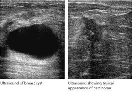
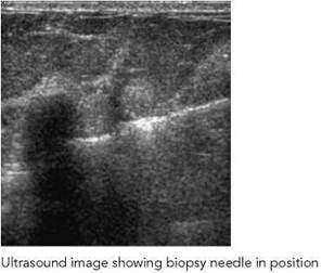
Ultrasound is the most widely used and readily available alternative imaging technique. It is the best test for determining whether a lesion is a cyst. Other fluid-containing diseases may also be detected, such as abscesses and duct ectasia. Intracystic tumours are rare but are seen better on ultrasound (often as an incidental finding) than on mammography. Ultrasound gives different tissue information from that obtained by X-ray (e.g. homogeneity of tissue, acoustic shadowing), making this a useful supplementary tool. It also allows assessment of fixation of surrounding tissue and vascularity. It may be used, therefore, to assess mammographically indeterminate masses or to guide core biopsy.
In younger patients, where the density of breast makes mammography less sensitive and where suspicion is lower, ultrasound has an important role in diagnosis and avoidance of radiation exposure.
Being a real-time technique, ultrasound is simpler and faster and will be the guidance method of choice for most interventional techniques, assuming that the lesion is visible.
Magnetic resonance imaging
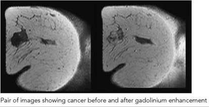
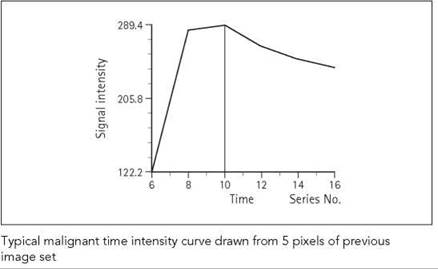
MRI is expensive, relatively time-consuming and not available widely. Some patients cannot tolerate it due to claustrophobia. In addition to showing the morphological features demonstrated by other modalities, a graph of signal against time after administration of intravenous gadolinium-based contrast agent allows quantification of the rate of tissue enhancement and gives a sensitive method of differentiating fibrosis (scarring) from recurrent tumour. Core biopsy is often preferred as it is quicker and more specific. MRI may be used to assess multiple lesions, implants and tissue around implants. It may be useful in some young patients who have a strong family history and will require many years of screening, or for screening of young patients after mediastinal radiotherapy for Hodgkin's lymphoma.
Nuclear medicine
Nuclear medicine is currently not a major modality in breast imaging. Scintimammography using technetium sestamibi will detect carcinoma with sensitivity and specificity equal to MRI in some series, but the expertise is not widely available. In most centres, core biopsy is more often used for assessment of indeterminate lesions.
Radionuclide imaging will have an increasing role to play as sentinel node biopsy replaces axillary dissection as the standard investigation for lymph nodes in the axilla. This will reduce the morbidity of breast surgery.
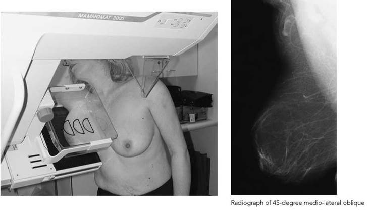
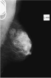
45-degree medio-lateral oblique (MLO) basic - Lundgren’s oblique
This projection demonstrates the greatest amount of breast tissue of any single projection. It was recommended by the Forrest Report 1986 as the single projection mandatory for screening mammography. In 1995, that advice was superseded and this projection, now done in conjunction with the cranio-caudal projection, is the routine examination of the breast. EC standards state that in a complete breast examination, there must be visually sharp reproduction of the whole glandular breast and visually sharp reproduction of the cutaneous and subcutaneous tissue, and the nipple should be parallel to the film.
Position of patient and cassette
• The mammographic equipment is routinely angled at 45 degrees from the vertical. However, the precise angulation required will depend on the woman, e.g. for a very thin woman, the breast-support table will be almost vertical.
• The anatomical marker is oriented vertically to prevent confusion of the image with those produced by other mammographic projections.
• The woman faces the equipment, with the breast about to be examined closer to the breast-support table. She has her feet apart for stability, in preparation for the leaning she will have to do later to achieve the correct position.
• The woman’s arm is placed on the top of the table, with the elbow flexed and dropped behind it. The table height is adjusted so that the lower border of the breast is 2-3 cm above the edge of the film.
• The radiographer places his or her hand against the rib cage and brings the breast forwards, with his or her thumb on the medial aspect of the breast. The breast is gently extended upwards and outwards to ensure it contacts the breast-support table. This is aided by leaning the woman forward.
• With the breast still supported manually, the shoulder on the side under examination is lifted and extended with the other hand to ensure inclusion of the axilla, the axillary tail and as much as possible of the breast tissue.
• The hand that is supporting the breast maintains an upward and outward lift on it, whilst the other hand is gently removing any skin folds, especially between the lateral aspect of the breast and the film support behind it.
• The compression plate is applied to fit into the angle between the humeral head and the chest wall. Great care must be taken not to hurt the woman, commonly in her ribs or sternum. Initially slightly pushing away the opposite side of the body, until the compression plate touches the breast, and then rotating it inwards again helps overcome this.
• When the compression is almost complete, the breast is checked for skin folds and the radiographer’s hand is removed. Premature removal will cause the breast to droop.
• The nipple must be in profile and about a third of the way up the film. To ensure that the entire breast back to the chest wall margin is included, the infra-mammary skin fold should be included if possible. Compression is adequate if, when the breast is squeezed gently, it feels firm.
Essential image characteristics
• The axilla, axillary tail, glandular tissue, pectoral muscle and infra-mammary fold should be demonstrated.
• The pectoral muscle should be demonstrated to nipple level.
• When both medio-lateral oblique projections are viewed together 'mirror image', they should be symmetrical, matching at the level of the pectoral muscle as a deep 'V' and at the inferior border of the breasts.
Common faults and remedies
• The breast may be positioned incorrectly. If the axillary area is not well demonstrated, then the breast-support table was too low and the axillary area and infra-mammary nodes will not be visualized. This can be rectified by ensuring, when positioning, that the nipple is a third of the way up the film.
• If the pectoral muscle is not well demonstrated, then this is due to the woman not leaning in towards the equipment, thus allowing the breast to relax, and not extending the arm and shoulder up and over the breast-support table adequately. The woman must be encouraged to lean in to the equipment and to stretch her arm and shoulder over the breast-support table to ensure inclusion of the pectoral muscle.
• There are several causes for all the breast tissue not being included on the film. If, in the initial positioning, the radiographer's hand was not placed against the woman's rib cage to ensure that the whole breast was present to be stretched across the breast-support table, then this must be rectified. If the woman was standing back from the breast-support table, then she must be encouraged to stand further forward.
• If it is the inferior aspect of the breast that is visualized inadequately, then this is because the woman was standing in a position where her feet and hips were not aligned with the rest of her body as it faced the equipment.
• If the lower border of the breast is cut off the film, then the film height was incorrect or the breast was released by the radiographer before adequate compression was applied to hold it in place.
• If the nipple is not in profile and there is no reason for this, e.g. inverted nipple, surgery, etc., then the woman's body was not parallel with the film support. If the woman stands too far forward, the nipple will rotate under the breast tissue. If she stands too far back, the nipple will lie above the midline and not all of the breast tissue will be demonstrated.
• An under-penetrated image with poor definition commonly results from inadequate compression. If compression was applied, then the usual cause is that the top edge of the compression plate was too near the humeral head, resulting in minimal compression being applied to the breast. This can be avoided by checking the breast tissue by gentle squeezing to ensure that it feels firm.
• If the exposure is incorrect, then this is usually due to incorrect centring of the glandular tissue over the automatic exposure chamber.
• Skin folds show as opaque linear shadows, which can obscure detail. Folds in the skin must be smoothed out while the breast is still supported manually, so that the movement does not alter the position of the breast. (See image below.)
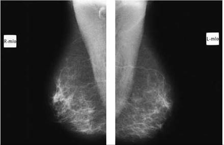
Two medio-lateral radiographs (right and left) presented for viewing
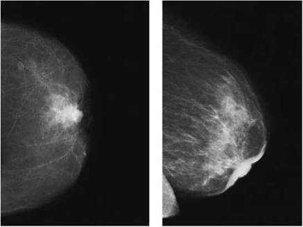
Left image shows cc view with nipple not in profile. Right image shows oblique view with nipple in profile for comparison. Note extensive radiotherapy changes make nipple more obvious
Cranio-caudal - basic
This projection demonstrates the majority of the breast, excluding the superior posterior portion, the axillary tail and the extreme medial portion (which contains less glandular tissue than the lateral portion).
Position of patient and cassette
• The mammography equipment is positioned with the X-ray beam axis pointing vertically downwards.
• The woman faces the machine, with her arms by her sides. She is standing and is rotated 15-20 degrees to bring the side under examination close to the horizontal breast-support table. The table is at the level of the infra-mammary crease.
• The radiographer stands on the side of the woman that is not being examined and lifts the breast up in the palm of the hand to form a right-angle with the body. It is rested on the breast- support table and the radiographer's hand is slipped out. The nipple should be in the midline of the breast and in profile.
• Film markers are placed on the axillary side of the film (by international convention) close to the woman's axilla and well away from the breast tissue.
• The woman's head is turned away from the side under examination, and the shoulder on the side under examination is dropped to promote coverage of the lateral posterior portion of the breast, to bring the outer quadrant of the breast in contact with the breast-support table, and to relax the pectoral muscle.
• The breast is then lifted up and rotated medially five to 10 degrees so that the nipple is just medial to the midline of the film. The position of the breast is checked to ensure that the nipple is still in profile.
• The breast is smoothed by the radiographer's hand to remove any skin folds and is also stretched carefully across the film support.
• As the hand is removed, the breast is compressed firmly to a level that the woman can tolerate (EC standards). This should result in an equal thickness of tissue anteriorly and posteriorly. A remote-controlled foot compression device allows this to be achieved more easily, as the radiographer then has both hands free.
• Care must be taken when the compression is applied to ensure that exposure is immediate. Compression must be released as soon as the exposure ends.

Normal cranio-caudal projection

Radiograph demonstrating nipple not in profile, in this case due to surgical distortion
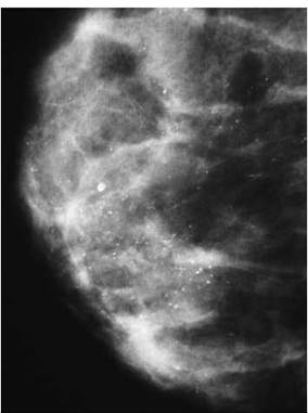
Radiograph showing two types of benign calcification
Radiograph of patient with pacemaker in situ
Essential image characteristics
• No overlying structures should be seen.
• The pectoral muscle will be seen in 30-40% of patients.
• The nipple should be in profile and shown medial to the midline of the film.
• The medial portion of the breast should be included on the film.
• There should be no folds in the breast tissue.
Common faults and remedies
• Overlying structures, such as the clavicle, the mandible or large earrings, may be seen. This can be prevented by taking care when positioning, using a deep compression plate, canting the head away from the tube, and removing earrings, respectively.
• The nipple may not be in profile. This is due most commonly to the cassette/image receptor holder being at the wrong height. If the support is too low, then the nipple will be tilted below the majority of the breast tissue; if it is too high, then the nipple will lie above the majority of the breast tissue.
• The nipple may also not be in profile if the skin on the underside of the breast is caught at the edge of the cassette/image receptor holder. The breast must be lifted and the underside of the breast pulled forward. If there is loose skin on the superior surface of the breast, then the nipple may not be positioned in profile. In such a case, the nipple position must be controlled by applying tension to the skin surface but not the underlying tissue as the compression is applied.
• If the nipple is not in profile in a woman with a fixed nipple, then no improvement can be made without the loss of visualization of breast tissue. Hence, either a clear view of the retro-areolar area is needed on the medio-lateral oblique projection or a supplementary projection of this area is essential.
• If the breast is positioned incorrectly, then areas of breast tissue will be lost from the image. If the medial portion of the breast is not on the film, then the breast has been overrotated. If the breast was rotated inadequately medially, then the lateral aspect of the breast will be lost.
• Folds in the breast tissue result if the breast is not smoothed out before compression is completed. As folds can obscure detail, e.g. micro-calcifications, great care must be taken to ensure that they do not occur.
• Under-penetrated images, which lack detail, are generally a result of inadequate compression. This can be overcome by checking the breast manually for firmness before exposure.
• Incorrect exposure when using an automatic exposure device is usually because the glandular portion of the breast was not positioned accurately over the ionization chamber.
Extended cranio-caudal - laterally rotated
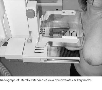
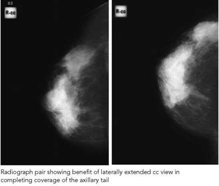
The routine cranio-caudal projection will not show many abnormalities in the upper quadrant of the breast, which will be demonstrated on the medio-lateral oblique projection.
As all lesions must be demonstrated on two projections, this extended cranio-caudal projection is useful for demonstrating the outer quadrant, axillary tail and axilla.
Position of patient and cassette
• The woman faces the equipment and the side under examination is rotated about 45 degrees to the equipment.
• The breast is elevated in the radiographer's hand to form a right-angle with the body and to position the nipple in profile. The breast-support table is raised to contact the inferior part of the breast closest to the chest wall.
• The hand is removed gently, leaving the breast with the nipple area on the extreme medial edge of the breast-support table.
• The woman's arm is placed on the side of the breast-support table holding the equipment.
• The radiographer stands behind the woman and lifts up the breast, extending it as far as possible to show as much breast tissue as possible.
• The woman leans back about 45 degrees if possible, depressing her shoulder to enable the outer quadrant and axilla to contact the breast-support table.
• The woman's arm is extended. She holds on to the equipment with her other hand for stability and to maintain her position.
• Whilst the breast is held in position on the breast-support table, the woman is asked to lean towards the equipment and is gently pushed in. If she cannot lean as far back as 45 degrees, then a satisfactory projection of the upper outer quadrant will still be possible provided that she is rotated adequately.
• The nipple must be kept in profile. Not all of the medial aspect of the breast will be demonstrated.
• The breast is supported manually while the compression is initiated. The hand is removed forwards but not until the compression is almost complete, so that the breast does not move.
• The compression plate fits into the angle between the humeral head and the rib cage.
Essential image characteristics
• The breast must be positioned so that the axillary tail is present on the film, with as much of the breast tissue as possible shown.
Common faults and remedies
• If the breast image shows insufficient axillary tail and axilla, then the nipple was not at the far medial edge of the film support before the woman leant back.
• If the nipple was not in profile, then the woman did not lean in enough to allow the medial part of the breast to be rotated inwards.
• If compression is inadequate, then the breast was not checked for firmness and the compression may have been too close to the humeral head.
• If the exposure is incorrect, then this is usually due to incorrect centring of the glandular tissue over the automatic exposure chamber.
• Folds in the breast tissue result if the breast is not smoothed out before compression is completed. As they can obscure detail, e.g. micro-calcifications, great care must be taken to ensure that they do not occur.

Radiograph of extended cranio-caudal - medially rotated projection
This is useful for demonstrating lesions in the medial portion of
the breast.
Position of patient and cassette
• The woman faces the equipment. Her sternum is about 8 cm from the medial edge of the breast-support table.
• Both breasts are lifted on to the breast-support table, which is lowered for this purpose. It is then raised to the correct height, enabling the nipple on the side under examination to be in profile.
• The woman is pushed gently towards the equipment.
• The breast to be demonstrated is stretched in and rotated to enable the medial posterior area to be visualized. The breast is held while the initial compression is applied. Then the radiographer's hand is removed so the final compression can be achieved.
Essential image characteristics
• The maximum inclusion of the medio-posterior part of the breast is demonstrated.
Common faults and remedies
• If the inner quadrant is not fully visible, then the woman needs to be encouraged to move further forward into the equipment and the medial part of the breast needs rotating more.
• If the nipple is not in profile, then the breast-support table was not at the correct height or the breast was not lifted and stretched enough.
• If compression is inadequate, then the film will be underexposed. The breast was not checked for firmness.
• If the exposure is incorrect and the film is under-penetrated, then this is usually due to incorrect centring of the glandular tissue over the automatic exposure chamber.
• Folds in the breast tissue result if the breast is not smoothed out before compression is completed. As they can obscure detail, e.g. micro-calcifications, great care must be taken to ensure that they do not occur.
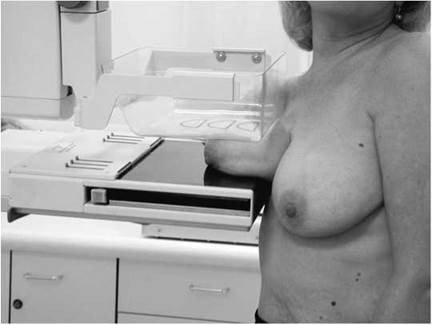
This projection is of value if a lesion was seen high in the axillary tail on the medio-lateral oblique but was not shown on the cranio-caudal projection. It demonstrates the axillary tail and the upper midline portion of the breast tissue.
Position of patient and cassette
• The breast-support table is horizontal and positioned slightly below the infra-mammary angle.
• The woman stands close to the equipment, with her breast aligned slightly to the medial side of the midline of the breast-support table. Her feet and hips point towards the table.
• The breast is lifted gently and placed on the table. The woman is then encouraged to lean 10-15 degrees laterally, extending her arm away from the side of her body. The woman should not rotate her body so that her thorax is positioned obliquely, but she must remain squarely facing the equipment.
• Compression is applied, the exposure made, and compression released immediately.
Essential image characteristics
• The nipple should be in profile.
• The anterior edge of the pectoral muscle lateral to the midline of the breast should be visualized.
Common faults and remedies
• This is a difficult position to achieve and maintain. It is essential that the woman's body remains square to the equipment and that she does not turn obliquely. Compression, exposure and release must be done expeditiously due to the awkward nature of this position.
• Folds in the breast tissue result if the breast is not smoothed out before compression is completed. As they can obscure detail, e.g. micro-calcifications, great care must be taken to ensure that they do not occur.
• Under-penetrated images, which lack detail, are generally a result of inadequate compression. This can be overcome by checking the breast manually for firmness before exposure.
• Incorrect exposure when using an automatic exposure device is usually because the glandular portion of the breast was not positioned accurately over the ionization chamber.

Radiograph of extended cranio-caudal projection showing a laterally placed mass
Lateral projections
Lateral projections are valuable in localizing areas of abnormality, e.g. micro-calcification, and in the clarification of suspicious lesions.
Lateral images are taken at 90 degrees to the cranio-caudal projection and show the relationship of lesions to the nipple.
Both medio-lateral and latero-medial projections can be taken. The medio-lateral is more common, because although the axillary area is not shown, more of the breast overall is visualized.
Medio-lateral
Position of patient and cassette
• The equipment is positioned with the tube and breast- support table vertical.
• The woman faces the equipment, with the breast-support table at the lateral side of the breast. The woman places her arm behind the breast-support table and holds the equipment for stability. She leans in from the waist to ensure that the breast tissue closest to the chest wall will be visualized.
• The equipment is adjusted to the height at which the inferior portion of the breast will be included.
• The radiographer's hand is placed against the side of the rib cage and slid forward to support the breast, the palm of the hand on the lateral aspect and the thumb on the medial aspect.
• The woman is pushed in gently and the breast extended outwards and upwards against the breast-support table, ensuring that the nipple remains in profile.
• The shoulder of the opposite side is pushed back so that the compression plate can be brought into contact with the breast under examination. Firm support of the breast is necessary at this time so that the breast tissue at the chest wall margin is not pulled away.
• Compression is applied gently. When the plate contacts the breast at the chest wall, the other shoulder is brought

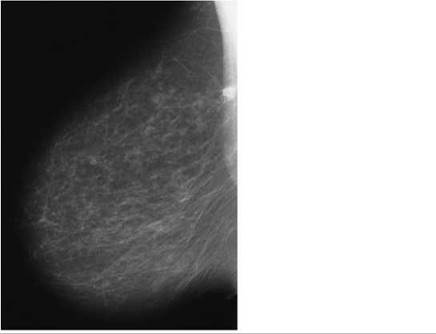
Radiograph of medio-lateral projection showing small tumour close to the chest wall
forward again to ensure that the woman is in a position for a true lateral projection.
• The breast position is maintained manually, with the radiographer using his or her other hand to remove any skin folds between the breast-support table and the lateral aspect of the breast.
• The hand is removed, ensuring that the position is maintained as final compression is applied.
Essential image characteristics
• The breast, including its inferior border, should be demonstrated adequately.
• There should be the same depth of tissue as in the cranio- caudal projection.
Common faults and remedies
• If all the breast tissue is not seen, then the radiographer's hand was not taken back to the rib cage and the breast not slid forward sufficiently across the breast-support table.
• If the nipple was not in profile, then the woman was standing too far in front of the breast-support table if the nipple lies behind the majority of the breast tissue, and too far behind if the nipple is lying in front of the majority of the breast tissue.
• If compression is inadequate, then the film will be underexposed. The breast was not checked for firmness.
• If the exposure is incorrect and the film under-penetrated, then this is usually due to incorrect centring of the glandular tissue over the automatic exposure chamber.
• Folds in the breast tissue result if the breast is not smoothed out before compression is completed. As they can obscure detail, e.g. micro-calcifications, great care must be taken to ensure that they do not occur.
• If the nipple of the other breast is demonstrated, then the other breast may need to be held back.
Latero-medial
Position of patient and cassette
• The breast-support table is placed against the sternum. The arm on the side being examined is lifted up to clear the X-ray tube and is rested on the equipment. The body is rotated inwards slightly to contact the breast-support table.
• The equipment height is altered in order that the lower border of the breast is included.
• The breast is gently guided across and upwards, ensuring that the nipple is in profile.
• Compression is applied while the radiographer's hand supports the breast. The hand is removed as final compression is achieved.
• This projection is taken for demonstration of medially situated lesions.
Essential image characteristics
• The breast is demonstrated fully, including its inferior border.
• The same depth of breast tissue should be visualized as on the cranio-caudal projection.
Common faults and remedies
• If not all of the breast is demonstrated, then the woman's body was not pushed in adequately.
• If the nipple was not in profile, then the arm was pulled over too much, thus rotating the body into an oblique position and causing the nipple to lie under the majority of the breast tissue.
• Folds in the breast tissue result if the breast is not smoothed out before compression is completed. As they can obscure detail, e.g. micro-calcifications, great care must be taken to ensure that they do not occur.
• Under-penetrated images, which lack detail, are generally a result of inadequate compression. This can be overcome by manually checking the breast for firmness before exposure.
• Incorrect exposure when using an automatic exposure device is usually because the glandular portion of the breast was not positioned accurately over the ionization chamber.
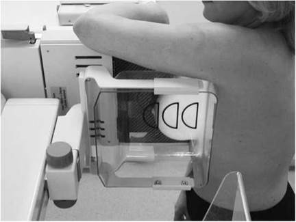
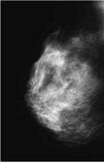
Radiograph of latero-medial projection

Radiograph demonstrating axillary tail projection
Axillary tail
This projection is valuable in women where lymph gland involvement of a breast carcinoma is suspected or there is accessory breast tissue, as it demonstrates tissue high into the axilla.
Position of patient and cassette
• The woman faces the equipment. Her feet are turned at an angle of approximately 15 degrees towards the midline. Her arm on the side under examination is raised and her hand placed on her head. She must remain close to the equipment.
• The equipment is at 45 degrees to the horizontal and level with the suprasternal notch and the humeral head when her arm is raised.
• The woman is leant forwards towards the machine so that the corner of the table is deep in the axilla.
• The radiographer should take hold of the woman's arm on the side under examination, from behind the breast-support table, and pull her arm and thus her humeral head firmly across the top of the breast-support table, ensuring that the corner of the film is deep in the axilla. The arm is rested on top of the table and the woman encouraged to lean against the cassette/image receptor holder.
• The breast is held forward by the radiographer, to ensure even thickness of the breast and to improve the compression of the axillary region.
• Compression is applied, the exposure made and compression released.
Essential image characteristics
• The axillary region must be demonstrated.
Common faults and remedies
• Inadequate compression can occur, visualized as an underpenetrated image with poor definition. This is often due to the humeral head or the clavicle being caught by the compression plate.
• Folds in the breast tissue result if the breast is not smoothed out before compression is completed. As they can obscure detail, e.g. micro-calcifications, great care must be taken to ensure that they do not occur.
• Incorrect exposure when using an automatic exposure device may result from the glandular portion of the breast being positioned inaccurately over the ionization chamber.
Localized compression/paddle projections
Localized compression/paddle projections can provide extra information in a suspicious area, e.g. by demonstrating whether the borders of a lesion are defined clearly or indistinctly.
The paddle projections required are usually selected by the radiologist, with the aim of repeating those projections that initially demonstrated the possible lesion.
A small compression paddle is needed, but the projections are done with a full-field diaphragm to allow landmarks to be identified.
For accurate localization of the region of interest, the original mammogram must be examined. It is essential that the radiographer measures and records the depth of the lesion from the nipple back towards the chest wall, the distance of the lesion from the nipple (above, below, medial or lateral), and the distance from the skin surface to the lesion.
Position of the patient and cassette
• The woman is positioned as for the original projection.
• The recorded coordinates are used to move the woman until the affected breast tissue lies over the automatic exposure control and the paddle is centred over it. Allowances have to be made for the fact that the coordinates recorded were from a fully compressed breast.
• The compression is applied sufficiently to hold the breast in place.
• The coordinates are then rechecked. Provided that the region of interest is centred under the paddle, the centring point is marked on the skin surface and compression applied fully.
• If the area of interest was not under the paddle on checking, then the woman's position is adjusted, before proceeding as above.
• The compression used should be firmer than usual. It is essential that the woman understands the purpose and necessity for this, to ensure her cooperation.

Mammogram showing ill-defined region, and repeat mammogram using paddle to show the effect of compression


Magnified projections
Projections of the breast using a magnification technique, using either a localized or full-field technique, are sometimes employed to give enhanced visualization of the breast architecture and detail, thus promoting better diagnosis.
• Magnification is used most commonly to examine areas of calcification.
• Magnified projections are done in the cranio-caudal and medio- lateral projections.
• A fine focus of 0.1mm2 is essential, and a magnification factor of two is commonly used.
• A specially designed platform or tower fits on to the breast- support table to allow this projection to be undertaken. Magnification factors are typically 1.5, 1.8 or 2.0.
• No grid is used.
• Small and large paddles may be utilized for magnified projections and a full-field diaphragm.
• The advantage of using a small paddle is that compression can be applied firmly to the area of interest. However, if the suspicious area, e.g. calcification, is extensive, then a larger paddle is needed to allow visualization of the entire area on the film.

Full-field magnified projections
• The woman is placed in the position for the lateral and cranio-caudal projections in turn.
• It is important to realize that the field will cover only the half of the breast under examination and that in large breasts some measuring may be needed.
Paddle-magnified projections
• As with standard paddle projections, the recording of the coordinates of the lesion from the original images and the positioning technique, as described above, is essential in order to accurately centre the lesion under the paddle.
• In magnified projections, the use of a fine focus will lengthen the exposure time greatly, and the projections should be taken on arrested respiration.
Stereotactic needle procedures
Due to improvements in the technical quality of mammography and the introduction of screening mammography, an increasing number of clinically impalpable breast lesions are being detected. These, like palpable lesions, require further radiological investigation to establish a diagnosis. Commonly, further mammographic projections and ultrasound examinations are undertaken to confirm the presence of the suspected abnormality and to assess its clinical importance. Any impalpable lesion that cannot be stated definitively to be benign after such procedures must have a tissue diagnosis. This is achieved by:
• image-guided FNA cytology; and/or
• image-guided core biopsy wherever possible.
Open surgical biopsy is thus avoided. Whilst FNA or core biopsy can be done freehand in palpable lesions, impalpable lesions produce unique problems.
Ultrasound-guided biopsy is preferable for impalpable lesions, since it is quick to perform, very accurate, and associated with minimal discomfort and morbidity to the woman. It is the guidance technique of choice for biopsy if the lesion is visualized clearly on ultrasound. X-ray-guided FNA, however, is essential if there is any doubt that what is seen on ultrasound is the same lesion as visualized on the mammograms, and when the lesion is not shown on ultrasound. The most accurate way of performing X-ray-guided FNA is using stereotactic equipment. Accuracy is clearly essential to ensure that the relevant area is sampled, as the definitive treatment, ranging from non-excision of a benign lesion to mastectomy in a malignant lesion, is based on the outcome of the cytological/histological sample. Two main types of stereotactic equipment exist: a purpose-built table where the woman lies prone, and an accessory that can be fitted to conventional mammographic equipment. The latter is described, since it is more common.
Any woman undergoing this procedure will be anxious, and a good rapport between the woman and the radiographer is essential. A thorough explanation of the procedure before it commences and at each step along the way is important as this will relax and reassure the woman.


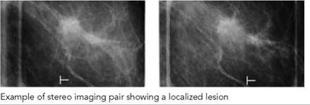


Technique
The way the breast is to be positioned for the localization to be done is agreed with the radiologist. The woman is seated and positioned, and the compression plate, with its integral window, is applied. An outline of the compression plate window is drawn on to the woman's skin so that any breast movement during the procedure is evident. The tube movements necessary to produce the stereo images are performed (typically the tube is swung 20 degrees to each side of the midline). The radiographs are processed as quickly as possible and the images checked with a radiologist, ensuring that the lesion is shown clearly and that it is not too close to the edge of the compression plate window. The coordinates of the lesion will be calculated by the equipment from the stereo images. A local anaesthetic injection to the skin over the biopsy area is given. The needle holder is positioned correctly, and the radiologist places the needle in the breast. A check film is essential after the first needle has been placed to confirm that the needle is located correctly. Aspiration is then performed. The procedure may be repeated with several needles, and multiple passes may be undertaken with each needle, if necessary.
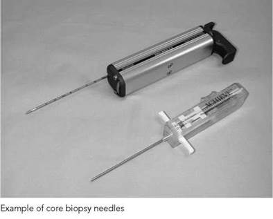
Modern equipment has a digital system for biopsy and spot imaging. The film processing is replaced with digital image acquisition and reconstruction, which can be done very swiftly and accurately. Core biopsy is performed in a similar way typically using a 14G wide-core biopsy needle.
Stereotactic preoperative marker
localization
This procedure is very similar to that described for stereotactic FNA or core biopsy. Whilst stereotactic equipment is not essential, it does increase the accuracy. The marker wire that is used instead of the fine needle or the biopsy gun will depend on the preferences of the surgeon performing the biopsy or excision. The purpose of this localization is for a marker wire to be placed accurately in the breast lesion so that the surgeon can perform a diagnostic biopsy of the lesion. It is essential that the marker wire tip lies within the lesion so accurate assessment of the depth of the abnormality in the compressed breast is made. The position of the wire in relation to the abnormality in the breast must therefore be checked mammographically after marker insertion.
Breast implants
As breast implants are radio-opaque, visualization of breast tissue is often not possible. This is especially so if the implant forms a large proportion of the breast. Women with breast implants and who attend for mammography need to be made aware of the limited nature of any mammographic examination performed on them. Breast awareness in these women is vital, and its value to them should be stressed. The radiologist in charge will have a policy regarding the mammography of these women, many of whom are still keen to be examined even though they recognize the limitations of this. Many radiologists prefer to undertake breast ultrasound or MRI in breasts substantially augmented with prosthetic material.
Women with implants may be embarrassed about them and/ or worried that mammography will cause them to rupture. Thus, establishing a rapport with the woman is vital.
Women with breast implants may be imaged using standard projections, tangential projections or the Eklund technique.
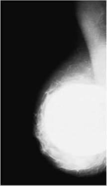
Mammogram showing appearance of a breast implant
Imaging procedure
• Using the standard technique, the cranio-caudal projection is undertaken first.
• The breast is positioned routinely, but compression is applied only to a point at which the breast will be held in position.
• A manual exposure must be set, as the AEC would not terminate the exposure due to the radio-opacity of the breast.
• The resultant mammogram is evaluated particularly with respect to exposure factors, and repeated if necessary.
• The medio-lateral oblique projection is then taken, with an increase of exposure factors of about one-third of those for the cranio-caudal projection.
Notes
• Tangential projections should be undertaken in any woman with breast implants and who is undergoing mammography due to a localized breast lump.
• The Eklund technique is suitable for women in whom there is a large volume of breast tissue relative to the prosthesis. The implant is displaced to the back of the breast so that only the breast tissue is compressed and imaged.
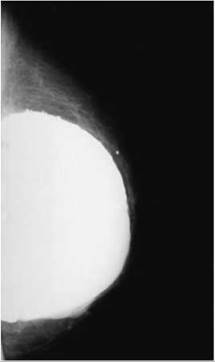
Mammogram showing appearance of a breast implant with surface irregularity due to ageing of the implant
Core biopsy and specimen tissue radiography
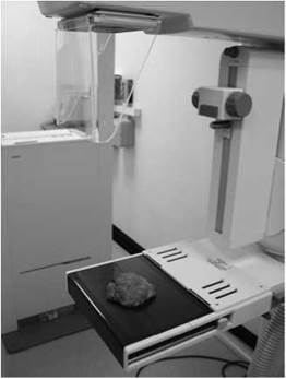

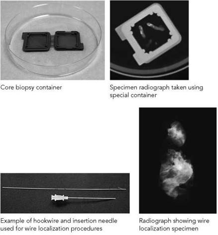
Core biopsy
Both core biopsy and specimen breast radiography, involving a magnification technique, play an important role in the diagnosis, management and treatment of breast cancer.
Breast tissue cores, which are obtained in the manner described on p. 461, are examined radiographically to determine the presence of a breast lesion that may contain or be solely composed of calcifications.
Procedure
Following core biopsy, the excised tissue cores are laid out on a fibre-free sheet or in a dedicated specimen holder kept moist with isotonic saline to prevent desiccation. Radiography may be performed on the mammography table using the magnification facility or in a specimen radiography cabinet.
Radiographic technique using specimen cabinet
The tissue cores on the fibre-free sheet are placed on top of an 18 X 24-cm cassette containing a single emulsion film. The tissue is exposed using an exposure of 26 kVp and 3 mAs.
Once adequate radiographs have been obtained, the tissue cores must be transferred to a fixative, usually formalin, and transported to the laboratory immediately for processing for subsequent histology.
Breast tissue radiography
Prior to surgical excision of a breast abnormality, a wire is inserted in the centre of the lesion using the stereotactic preoperative marker localization technique, as described on p. 461.
Following excision of the breast abnormality, the breast tissue specimen is sent for radiographic examination while the patient is still under anaesthetic to ensure that there is a minimum 1 cm clear margin of normal breast tissue surrounding the lesion.
The radiographic procedure is performed while the patient is still under anaesthetic; thus, the procedure is carried out as quickly and as efficiently as possible.
Procedure
The procedure may be performed on the mammography table using the magnification facility or in a specimen radiography cabinet and using an 18 X 24-cm cassette containing a single emulsion film.
Two projections of the specimen are obtained, each image at right-angles to the other.
The specimen is first positioned on one half of the film, with the other half masked with lead rubber, and an exposure is made with careful collimation of the beam. The specimen is then positioned on the other half of the film and turned through 90 degrees.