
The importance of plain radiography of the skull has diminished in recent years due to the widespread availability of imaging modalities such as computed tomography (CT) and magnetic resonance imaging (MRI). These play a much more significant role in the management of a patient with a suspected intracranial pathology and either one would usually be the modality of choice if such a pathology were suspected. Plain radiography does, however, still play a significant role in the management of patients with certain skeletal conditions and, to a limited extent, in trauma, e.g. when a depressed or penetrating injury is suspected or if the patient is difficult to assess. Consequently, a significant number of referrals are still received from the accident and emergency department.
In order to produce high-quality images of the cranium and minimize risk for the patient, the radiographer must have a good understanding of the relevant anatomy, positioning landmarks and equipment used for imaging. This should be coupled with an ability to assess the patient's ability and thus apply the correct technique in any given situation.
This chapter will enable the radiographer to balance the technical factors with individual patient needs in order to maximize diagnostic outcome.
Interpretation of skull images
Skull films are recognized to be among the most difficult to interpret due to the complexity of the bony construction (numerous bones joined by sutures) and arterial and venous markings in the diploe, all of which may mimic fracture. Anteriorly, the complex facial skeleton is superimposed over the lower part of the skull vault; the dense petrous temporal bone also obscures detail. Fractures of the skull base are important because of the risk of cerebrospinal fluid (CSF) leak and spread of infection to the intracranial contents, but they are hard to demonstrate due to the thin, flat nature of the bones and superimposition of the facial skeleton and petrous bone.
Superimposition of other unwanted structures, including ponytails, hair clips, and hair matted with blood, can cause confusion. Surgical clips used for wound closure should not cause confusion, and they may help by marking the site of injury.
The initial interpretation of a skull film series will often be done by a clinician who is relatively inexperienced in trauma radiology. They will need the highest-quality examination possible.
Landmarks
• Outer canthus of the eye: the point where the upper and lower eyelids meet laterally.
• Infra-orbital margin/point: the inferior rim of the orbit, with the point being located at its lowest point.
• Nasion: the articulation between the nasal and frontal bones.
• Glabella: a bony prominence found on the frontal bone immediately superior to the nasion.
• Vertex: the highest point of the skull in the median sagittal plane.
• External occipital protuberance (inion): a bony prominence found on the occipital bone, usually coincident with the median sagittal plane.
• External auditory meatus: the opening within the ear that leads into the external auditory canal.
Lines
• Inter-orbital (inter-pupillary) line: joins the centre of the two orbits or the centre of the two pupils when the eyes are looking straight forward.
• Infra-orbital line: joints the two infra-orbital points.
• Anthropological baseline: passes from the infra-orbital point to the upper border of the external auditory meatus (also known as the Frankfurter line).
• Orbito-meatal base line (radiographic baseline): extends from the outer canthus of the eye to the centre of the external auditory meatus. This line is angled approximately 10 degrees to the anthropological baseline.
Planes
• Median sagittal plane: divides the skull into right and left halves. Landmarks on this plane are the nasion anteriorly and the external occipital protuberance (inion) posteriorly.
• Coronal planes: these are at right-angles to the median sagittal plane and divide the head into anterior and posterior parts.
• Anthropological plane: a horizontal plane containing the two anthropological baselines and the infra-orbital line. It is an example of an axial plane. Axial planes are parallel with this plane.
• Auricular plane: perpendicular to the anthropological plane. Passes through the centre of the two external auditory meatuses. It is an example of a coronal plane.
The median sagittal, anthropological and coronal planes are mutually at right-angles.
Anatomical terminology
All radiography of the skull is undertaken with reference to a series of palpable landmarks and recognized lines or planes of the skull. It is vital that the radiographer possesses a good understanding of these before undertaking any positioning.

Radiographic anatomy for positioning


Radiographic anatomy for positioning (contd)
In order to evaluate radiographs successfully, it is important to be aware of a range of anatomical features. This will enable a judgement to be made in relation to the quality of the radiograph with respect to positioning.
The radiographs below show a range of features that are used in image evaluation and will be referred to regularly in the remainder of this chapter.


Radiography of the skull can be carried out using a specialized skull unit, or with an ordinary Bucky, or simply with a stationary grid and tube. Each method has specific advantages and disadvantages in any given situation, and these will be considered later. Problems arise for the radiographer, as the different methods use slightly different imaging techniques, which in turn utilize different planes and beam angulations to achieve the same projection. It is important for the radiographer to be fully aware of each technique in order to maximize the diagnostic outcome for their patients.
Skull units
Images taken on skull units yield the highest-quality skull images. All aspects of tube and tube support design have been optimized for skull radiography. Their use is to be recommended when undertaking skull radiography, provided that the patient's condition will allow them to be moved on to the table.
Advantages include:
• reduction in distortion;
• high-resolution images resulting from a grid with a large number of gridlines per unit length (grid lattice) and very fine focal spot on the tube anode (typically 0.3-0.4 mm2);
• projections that are accurate and consistent as the patient is placed in one or a limited number of positions and the tube is then positioned around the head once this position is achieved;
• it can be more comfortable for the patient, as only one position has to be achieved;
• purpose-designed circular collimators allow close collimation to the head, reducing the dose and minimizing secondary radiation.
Equipment
Disadvantages include:
• the table on which the patient lies is often quite narrow and difficult to get on to; this may make it unsuitable for patients who are unable to cooperate, since they may fall off;
• most units are accompanied by their own technique manual requiring the radiographer to acquire a set of skills unique to one piece of equipment;
• units are expensive;
• units can be lacking in versatility for sick patients and patients with conditions such as thoracic kyphosis.
Types of skull unit include the following:
• Isocentric skull unit: this is the most widely available unit and will produce the highest-quality images. This is achieved by the design of the equipment, which ensures that the image-receptor plate and primary beam are always perpendicular to each other, thus eliminating distortion. Note that the point around which the tube pivots is always adjusted so that it is at the centre of the object of interest. The technique used by each manufacturer will vary slightly, but all use the anthropological baseline rather than the radiographic baseline when describing projections.
• Lysholm skull unit: this differs from the isocentric skull unit in that the point around which the tube pivots is always in the same plane as the film. This has the potential to produce distorted images if large angulations are used. The techniques used to operate these units are very similar to those for skull radiography carried out with a simple tube and Bucky and utilize the radiographic baseline when describing techniques. This type of skull unit is not used widely in modern imaging departments.
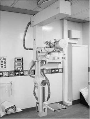
Isocentric skull unit
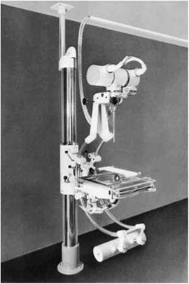
Lysholm skull unit
Positioning terminology
To describe a skull projection, it is necessary to state the relative positions of the skull planes to the image receptor and the central ray relative to skull planes/image receptor and to give a centring point or area to be included within the beam.
Traditionally, a centring point has always been given, but this may not always be appropriate. This is because some centring points will lead to the irradiation of a large number of radiosensitive structures that are of no diagnostic interest. Rather than focusing entirely on centring points, it is often better for the radiographer to be mindful of the anatomy that needs to be demonstrated for a diagnosis to be made and to ensure that this is included within the primary beam, whilst ensuring that it is not obscured by other structures.
Beam angulation
Many occipto-frontal and front-occipital projections will require the central ray to pass along the sagittal plane at some angle to the orbital-meatal plane. In these cases, the degree of angulation is stated after the name of the projection. The direction of angulation is also given. Caudo-cranial angulation (usually shortened to cranial angulation) involves the beam pointing up the body towards the head (written in short form as Î). If the beam is angled towards the feet, the beam is then said to be angled cranio-caudally (usually shortened to caudal angulation, and written in short form as J-).
The photograph below shows a fronto-occipital 30-degree caudal projection (FO30° J-).
Occipito-frontal projections


Projections in which the central ray is parallel to the sagittal plane are named according to the direction of the central ray. In the photograph above, the central ray enters the skull through the occipital bone and exits through the frontal bone. This is therefore an occipto-frontal (OF) projection.
Fronto-occipital projections

Again, the central ray is parallel to the sagittal plane, except that the central ray now enters the skull through the frontal bone and exits through the occipital bone. This is a fronto-occipital (FO) projection.
Lateral
For the lateral projection, the central ray passes along a coronal plane at right-angles to the median sagittal plane. It is named according to the side of the head nearer to the image receptor. In the example below, the beam enters the head on the left side, passes along a coronal plane, and exits the head on the right side, where the image receptor is located. This is, therefore, a right lateral.

Lateral with angulation
If the central ray passes along a coronal plane at some angle to the median sagittal plane, then the degree of angulation is stated. The photograph below shows a right lateral with 30-degree caudal angulation (R Lat 30°i).

Oblique projections
As can be seen in the photograph, an oblique projection is obtained when the central ray is at some angle to the median sagittal plane and the coronal plane. How the projection is named will depend on two factors: first whether the anterior or posterior portion of the head is in contact with the cassette and second whether the left or right side of the head is in contact with the cassette.
Forty-degree left anterior oblique
In this example, the head is rotated to the right, such that the median sagittal plane is at 40 degrees to the cassette and the left side of the head is in contact with the cassette (40°LAO).

Complex oblique projections
Oblique projections may become more complex when there is an additional caudal or cranial angle added in relation to a specified baseline. This additional angle is usually achieved by raising or lowering the chin, such that the relevant baseline makes the required angle to the cassette. Alternatively, the tube can be angled or a combination of both approaches may be useful if the patient has limited mobility. The photograph on the top right is an example of one such projection used for plain imaging of the optic foramina.
Fifty-five-degree left anterior oblique with 35 degree caudal angulation
The head has been rotated, such that the right side of the face is in contact with the cassette and the median sagittal plane makes
Positioning terminology
an angle of 55 degrees to the Bucky. In the example below, the central ray has a 35-degree caudal angulation. Alternatively, this angulation may be achieved by raising the orbito-meatal plane by 35 degrees whilst using a horizontal beam (55°LAO35°-f).


The photograph below shows how the same projection has been achieved with a combination of tube and orbital-meatal plane angulation. In this case, the plane has been raised 20 degrees and the tube has been given a 15-degree caudal angulation, in effect producing a total beam angulation of 35 degrees to the orbital-meatal plane.

Warning
When undertaking oblique skull radiography, always ensure that the beam is angled in the same direction as the grid lattice, i.e. parallel to the grid lines. If any angulation is applied such that beam is angled across the grid lines, i.e. perpendicular to their direction of travel, then a grid cut-off artefact will result and the image will need to be repeated.
Patient preparation
Before undertaking skull radiography, the following specific considerations should be made:
• Ensure that all metal objects are removed from the patient, e.g. hair clips and hairpins.
• Bunches of hair often produce artefacts and thus should be untied.
• If the area of interest includes the mouth, then false teeth containing metal and metal dental bridges should be removed.
• The patient should be provided with a clear explanation of any movements and film positions associated with the normal operation of the skull unit.
Useful accessories
• The usefulness of foam pads as an aid to immobilization cannot be overstated. The photograph opposite shows a specially designed pad for skull radiography. It is available in a range of sizes to accommodate different age groups.
• Forty-five-degree triangular pads are extremely useful for immobilizing children. They can be held by the parent and support the head without the parent placing their hands in the primary beam.
• Individual side markers are essential for skull radiography, as the clip-type side markers are easily lost in the collimation, particularly when using a skull unit.
• Velcro straps are of great use when immobilizing a patient on a skull unit.
General image quality guidelines and radiation protection considerations
The European Guidelines on Quality Criteria for Diagnostic Images describe various criteria by which images should be assessed. Many of these criteria are included with the specific projection descriptions and in the introduction to this chapter, but some more general points and other considerations are included below:
• Images should have a visually sharp reproduction of all structures, such as outer and inner lamina of the cranial vault, the trabecular structure of the cranium, the various sinuses and sutures where visible, vascular channels, petrous part of the temporal bone and the pituitary fossa.
• Important image details should be in the 0.3-0.5 mm range.
• A 400 (regular) speed imaging system is recommended (regular conventional film/screen combination).
• Use 70-85 kV tube voltage.
• Whenever possible, use an occipito-frontal (postero-anterior) rather than a fronto-occipital (antero-posterior) technique, since this vastly reduces the dose to the eyes.
• 24 X 30-cm cassettes are generally used for plain skull radiography.
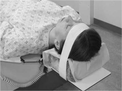
Patient immobilized using Velcro straps
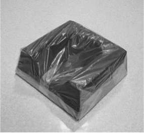
Immobilization pads used in skull radiography

Immobilization of a child using 45-degree foam pads
Guide to skull technique: recommended technique
The flowchart below can be used as a guide to help select the correct skull technique in any given clinical situation. The choice of projections will vary from department to department, depending on local protocols.

Non-isocentric skull technique should be undertaken when there is no isocentric skull unit available or the patient’s condition will not allow them to be transferred on to the skull unit table. Images are acquired using a 24 X 30-cm cassette. Grid cassettes are used when it is impossible to use a Bucky grid system.
Lateral - supine with horizontal beam
Position of patient and cassette
• The patient lies supine, with the head raised and immobilized on a non-opaque skull pad. This will ensure that the occipital region is included on the final image.
• The head is adjusted, such that the median sagittal plane is perpendicular to the table/trolley and the interorbital line is perpendicular to the cassette.
• Support the grid cassette vertically against the lateral aspect of the head parallel to the median sagittal plane, with its long edge 5 cm above the vertex of the skull.
Direction and centring of the X-ray beam
• The horizontal central ray is directed parallel to the interorbital line, such that it is at right-angles to the median sagittal plane.
• Centre midway between the glabella and the external occipital protuberance to a point approximately 5 cm superior to the external auditory meatus.
• The long axis of the cassette should be coincident with the long axis of the skull.
Essential image characteristics
• The image should contain all of the cranial bones and the first cervical vertebra. Both the inner and outer skull tables should be included.
• A true lateral will result in perfect superimposition of the lateral portions of the floors of the anterior cranial fossa and those of the posterior cranial fossa. The clinoid processes of the sella turcica should also be superimposed (see p. 232).
Radiological considerations
• This projection is performed as part of the Advanced Trauma and Life Support (ATLS) primary screen.
• Skull-base fractures are potentially life-threatening due to the risk of intracranial infection and are often very difficult to detect. Lateral skull projections taken supine with a horizontal beam may reveal sinus fluid levels, which may be a marker of skull-base injury. They may also help to confirm the presence of free intracranial air, which is another sign of breach of the integrity of the cranium.
Common faults and remedies
• Failure to include the occipital region as a result of not using a pad that ensures the head is raised far enough from the table/ trolley surface.
• Poor superimposition of the lateral floors of the cranial fossa. Always ensure that the inter-orbital line is perpendicular to the film and that the median sagittal plane is exactly perpendicular to the table/trolley top.
Notes
• The choice of lateral will depend on the site of the suspected pathology.
• If the suspected pathology is to the left side of the head, then a left lateral should be undertaken with the cassette supported on the left side of the patient, and vice versa. This will ensure that the pathology is shown at the maximum possible resolution due to the minimization of geometric unsharpness.
• This is the projection of choice for the majority of trauma cases on a trolley.


Cranium
Lateral - erect
This position may be used for a cooperative patient. Variations from the supine horizontal beam technique are noted below, but all other imaging criteria remain the same.
Position of patient and cassette
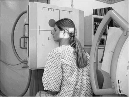
• The patient sits facing the erect Bucky and the head is then rotated, such that the median sagittal plane is parallel to the Bucky and the inter-orbital line is perpendicular to it.
• The shoulders may be rotated slightly to allow the correct position to be attained. The patient may grip the Bucky for stability.
• Position the cassette transversely in the erect Bucky, such that its upper border is 5 cm above the vertex of the skull.
• A radiolucent pad may be placed under the chin for support.
Direction and centring of the X-ray beam
• The X-ray tube should have been centred previously to the Bucky.
• Adjust the height of the Bucky/tube so that the patient is comfortable (NB: do not decentre the tube from the Bucky at this point).
• Centre midway between the glabella and the external occipital protuberance to a point approximately 5 cm superior to the external auditory meatus.
Common faults and remedies
This is not an easy position for the patient to maintain. Check the position of all planes immediately before exposure, as the patient probably will have moved.
Notes
• This projection can also be performed with the patient prone on a floating-top table.
• The projection may be performed usefully on babies in the supine position, with the head rotated to either side.
• An air/fluid level in the sphenoid sinus (an indicator for a base-of-skull fracture) will not be visible if the patient is imaged with a vertical central ray. This is not relevant in young babies, as the sinus is not developed fully.
Occipito-frontal
Occipito-frontal projections can be employed with different degrees of beam angulation. The choice of projection will depend upon departmental protocol and the anatomy that needs to be demonstrated.
Position of patient and cassette
• This projection may be undertaken erect or in the prone position. The erect projection will be described, as the prone projection is uncomfortable for the patient and will usually be carried out only in the absence of a vertical Bucky.
• The patient is seated facing the erect Bucky, so that the median sagittal plane is coincident with the midline of the Bucky and is also perpendicular to it.
• The neck is flexed so that the orbito-meatal base line is perpendicular to the Bucky. This can usually be achieved by ensuring that the nose and forehead are in contact with the Bucky.
• Ensure that the mid-part of the frontal bone is positioned in the centre of the Bucky.
• The patient may place the palms of each hand either side of the head (out of the primary beam) for stability.
• A 24 X 30-cm cassette is placed longitudinally in the Bucky tray. Ensure that the lead name blocker will not interfere with the final image.
Direction and centring of the X-ray beam
Occipito-frontal
• The central ray is directed perpendicular to the Bucky along the median sagittal plane.
• A collimation field should be set to include the vertex of the skull superiorly, the region immediately below the base of the occipital bone inferiorly, and the lateral skin margins. It is important to ensure that the tube is centred to the middle of the Bucky.
Occipito-frontal caudal angulation:
10, 15 and 20 degrees
• The technique used for these three projections is similar to that employed for the occipito-frontal projection, except that a caudal angulation is applied. The degree of angulation will depend on the technique, e.g. for an OF20°i projection, a 20-degree caudal angulation will be employed.
• Ensure that the central ray is always centred to the middle of the Bucky once the tube angulation has been applied and not before.
Essential image characteristics
• All the cranial bones should be included within the image, including the skin margins.
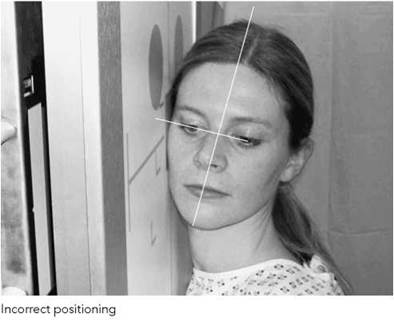
• It is important to ensure that the skull is not rotated. This can be assessed by measuring the distance from a point in the midline of the skull to the lateral margin. If this is the same on both sides of the skull, then it is not rotated.

Positioning for occipito-frontal skull projection

Positioning for OF10°4 skull projection

Positioning for OF20°4 skull projection

Alternative positioning for OF20°4 using a straight tube with the orbito-meatal baseline raised 20 degrees

Occipito-frontal
• The degree of beam angulation can be evaluated from an assessment of the position of the petrous ridges within the orbit:
- Occipito-frontal: the petrous ridges should be completely superimposed within the orbit, with their upper borders coincident with the upper third of the orbit.
- OF10°i: the petrous ridges appear in the middle third of the orbit.
- OF15°i: the petrous ridges appear in the lower third of the orbit.
- OF20°i: the petrous ridges appear just below the inferior orbital margin.
Radiological considerations
• Asymmetry of projection of the squamo-parietal suture due to rotation increases the risk of it being mistaken for a fracture.
• As the beam angle increases, more of the orbital region is demonstrated and less of the upper part of the frontal bone anterior parietal bones is shown. Thus, the site of the suspected pathology should be considered when selecting the beam angle, e.g. an injury to the upper orbital region is best evaluated with an OF20°i projection.
Common faults and remedies
• Rotation: ensure that the patient's head is straight immediately before the exposure is made.
• Incorrect beam angulation: it is worth remembering that greater beam angulations will result in the petrous ridges appearing further down the orbit. If an OF20°i is undertaken and the petrous bones appear in the middle third of the orbit, then a greater angle should have been applied, in this case a further 10 degrees.
Notes: alternative technique
• Patients often find it difficult to maintain their orbito-meatal baseline perpendicular to the film, as this is an unnatural position and they are likely to move.
• Instead of angling the beam to achieve the desired position of the petrous ridge within the orbit, a vertical central ray, i.e. perpendicular to the film, can be used. The desired angulation for the projection can then be achieved by raising the orbito-meatal baseline by the desired angle, e.g. for an OF20°i, the chin can be raised such that the orbito-meatal baseline will be at an angle of 20 degrees to the horizontal (see photograph). Similarly, for an OF10°i, the orbito-meatal line will be raised by 10 degrees.
Fronto-occipital
Fronto-occipital projections of the skull will demonstrate the same anatomy as occipito-frontal projections. The orbits and frontal bone, however, will be magnified, since they are positioned further from the image receptor.
Such projections should be carried out only when the patient cannot be moved and must be imaged supine. These projections result in increased eye dose and loss of resolution of anterior skull structures due to increased object-to-film distance (OFD).
Position of patient and cassette
• The patient lies supine on a trolley or Bucky table, or with the posterior aspect of the skull resting on a grid cassette.
• The head is adjusted to bring the median sagittal plane at right- angles to the film and coincident with its midline. In this position, the external auditory meatuses are equidistant from the cassette.
• The orbito-meatal baseline should be perpendicular to the cassette.
Direction and centring of the X-ray beam
All angulations for fronto-occipital projections are made cranially.
Fronto-occipital
• The central ray is directed perpendicular to the cassette or Bucky along the median sagittal plane.
• A collimation field should be set to include the vertex of the skull superiorly, the base of the occipital bone inferiorly, and the lateral skin margins. It is important to ensure that all of the tube is centred to the middle of the Bucky.
Fronto-occipital caudal angulation:
10, 15 and 20 degrees
• The technique used for these three projections is similar to that employed for the occipito-frontal, except that a cranial angulation is applied. The degree of angulation will depend on the projection required.
• Remember that the cassette or Bucky must be displaced superiorly to allow for the tube angulation, otherwise the area of interest will be projected off the film. For a 20-degree angle, the top of the cassette will need to be 5 cm above the skull vertex.
Essential image characteristics and
radiological considerations
See occipito-frontal projections (p. 240).
Common faults and remedies
See occipito-frontal projections (p. 241).
• Remember that increasing the degree of cranial angulation will project the petrous ridges further down the orbits.


Notes: alternative technique
See occipito-frontal projections (p. 241).
• In the example given below, an FO20°4 projection is required, but the patient can only maintain their orbito-meatal base line in a position 10 degrees back from perpendicular (i.e. with the chin raised slightly). In order to achieve an overall 20-degree angle, a ten-degree cranial angulation will need to be applied to the tube.
• Similarly, if the patient's chin was raised such that the baseline was 20 degrees to the perpendicular, then an FO20°4 projection could be achieved by using a straight tube perpendicular to the film.

FO 30°T 'Towne's projection'

The chin is raised, such that the baseline makes an angle of 10 degrees to the perpendicular and therefore a 40-degree tube angle must be employed to ensure a 30-degree angle to the orbito-meatal plane
Half-axial, fronto-occipital 30 degrees caudad - Towne's projection
Position of patient and cassette
• The patient lies supine on a trolley or Bucky table, with the posterior aspect of the skull resting on a grid cassette.
• The head is adjusted to bring the median sagittal plane at right- angles to the cassette and so it is coincident with its midline.
• The orbito-meatal base line should be perpendicular to the film.
Direction and centring of the X-ray beam
• The central ray is angled caudally so it makes an angle of 30 degrees to the orbito-meatal plane.
• Centre in the midline such that the beam passes midway between the external auditory meatuses. This is to a point approximately 5 cm above the glabella.
• The top of the cassette should be positioned adjacent to the vertex of the skull to ensure that the beam angulation does not project the area of interest off the bottom of the image.
Essential image characteristics
• The sella turcica of the sphenoid bone is projected within the foramen magnum.
• The image must include all of the occipital bone and the posterior parts of the parietal bone, and the lambdoidal suture should be visualized clearly.
• The skull should not be rotated. This can also be assessed by ensuring that the sella turcica appears in the middle of the foramen magnum.
Radiological considerations
• The foramen magnum should be seen clearly on this projection. The margins may be obscured by incorrect angulation, thus hiding important fractures.
• The zygoma may be seen well on this projection. If fractured, this gives a clue to the presence of associated facial injury.
Common faults and remedies
• Under-angulation: the foramen magnum is not demonstrated clearly above the petrous ridges. This is probably the most common fault, as the patient may find it difficult to maintain the baseline perpendicular to the film.
• If the patient's chin cannot be depressed sufficiently to bring the orbito-meatal baseline perpendicular to the film, then it will be necessary to increase the angle of the tube more than 30 degrees to the vertical. A 30-degree angle to the orbito-meatal plane must be maintained (see figure).
• Over-angulation: the posterior arch of the atlas bone (C1) is visible within the foramen magnum.
(contd)
Half-axial, fronto-occipital 30 degrees caudad - Towne's projection (contd)
• The large tube angle introduces a significant degree of distortion in the final image. This is eliminated using the isocentric skull unit technique.
• Some patients, particularly those with an increased thoracic kyphosis, may have difficulties in positioning the back of their head against the Bucky. This can be overcome somewhat by angling the Bucky table as shown in the photograph.
Notes: alternative technique
• Some or all of the 30-degree angle required for this projection can be applied by using a skull board. If a 30-degree board is used and the patient's orbito-meatal baseline is perpendicular to the top of the board, then a vertical central ray should be employed. If a 15-degree board is used, then a 15-degree caudal angulation must be applied.
• If a skull board with a 20-degree angle is used, then a 10- degree caudal angulation will be required to give the correct overall beam angulation.
Modified half axial
Denton (1998) has suggested an alternative projection that avoids irradiating the eyes and thyroid.
• The central ray is angled caudally so it makes an angle of 25 degrees to the orbito-meatal plane.
• Instead of using a centring point, a collimation field is set. The lower border of this field should be limited immediately above the supraorbital ridges at their highest point. The upper border of the light beam should just include the vertex of the skull at its highest point. Collimate laterally to include the skin margins within the field.

The Bucky can be tilted for kyphotic patients

F030°i Towne's projection using a 30-degree skull board

F030°↓ Towne's projection using a 15-degree skull board

Modified half axial

Reverse Towne's

Reverse Towne's, alternative positioning

Under angled Towne's
Occipito-frontal 30-degree cranial angulation - reverse Towne's projection
Position of patient and cassette
• This projection is usually undertaken with the patient in the erect position and facing the erect Bucky, although it may be performed prone.
• Initially, the patient is asked to place their nose and forehead on the Bucky table. The head is adjusted to bring the median sagittal plane at right-angles to the cassette and so it is coincident with its midline.
• The orbito-meatal baseline should be perpendicular to the cassette.
• The patient may place their hands on the Bucky for stability.
Direction and centring of the X-ray beam
• The central ray is angled cranially so its makes an angle of 30 degrees to the orbito-meatal plane.
• Adjust the collimation field, such that the whole of the occipital bone and the parietal bones up to the vertex are included within the field. Avoid including the eyes in the primary beam. Laterally, the skin margins should also be included within the field.
Essential image characteristics
• The sella turcica of the sphenoid bone is projected within the foramen magnum.
• The image must include all of the occipital bone and the posterior parts of the parietal bone, and the lambdoidal suture should be visualized clearly.
• The skull should not be rotated. This can also be assessed by ensuring that the sella turcica appears in the middle of the foramen magnum.
Radiological considerations
• The foramen magnum should be seen clearly on this projection. The margins may be obscured by incorrect angulation, thus hiding important fractures.
• The zygoma may be seen well on this projection. If fractured, this gives a clue to the presence of associated facial injury.
Common faults and remedies
See Half-axial, fronto-occipital 30 degrees caudad - Towne's projection (p. 244).
Notes
• This projection will carry a lower radiation dose to sensitive structures than the equivalent antero-posterior projection.
• Positioning may be easier to undertake on patients who find it difficult to achieve the position required for the equivalent antero-posterior half-axial projections.
Submento-vertical
Position of patient and cassette
The patient may be imaged erect or supine. If the patient is unsteady, then a supine technique is advisable.
Supine
• The patient's shoulders are raised and the neck is hyperextended to bring the vertex of the skull in contact with the grid cassette or table.
• The head is adjusted to bring the external auditory meatuses equidistant from the cassette.
• The median sagittal plane should be at right-angles to the cassette along its midline.
• The orbito-meatal plane should be as near as possible parallel to the cassette.
Erect
• The patient sits a short distance away from a vertical Bucky.
• The neck is hyperextended to allow the head to fall back until the vertex of the skull makes contact with the centre of the vertical Bucky.
• The remainder of the positioning is as described for the supine technique.
Direction and centring of the X-ray beam
• The central ray is directed at right-angles to the orbito-meatal plane and centred midway between the external auditory meatuses.
Essential image characteristics
• A correct projection will show the angles of the mandible clear of the petrous portions of the temporal bone.
• The foramina of the middle cranial fossa should be seen symmetrically either side of the midline.
Radiological considerations
• Erosion of the bony margins of the skull-base foramina is an important indicator of destruction by tumour. Under-tilt, over-tilt and rotation reduce the visibility of these foramina.
• This is now an uncommon projection, as CT demonstrates more completely the bony detail of the skull base in axial and coronal planes. MRI offers multiplanar imaging with superb detail of the soft tissues as well as the skull base.
Common faults and remedies
• This projection involves positioning that is very uncomfortable for the patient. It is well worth ensuring that the equipment is prepared fully before commencing the examination, so that the patient need maintain the position for only a minimum period.
• The position is achieved much more easily if a skull unit is used, since the object table and tube can be adjusted to minimize hyperextension of the neck.

Submento-vertical (SMV) using skull unit

Sella turcica: lateral
Position of patient and cassette
• The patient sits facing the erect Bucky and the head is then rotated, such that the median sagittal plane is parallel to the Bucky and the inter-orbital line is perpendicular to the Bucky.
• The shoulders may be rotated slightly to allow the correct position to be attained. The patient may grip the Bucky for stability.
• The head and Bucky heights are adjusted so that the centre of the Bucky is 2.5 cm vertically above a point 2.5 cm along the baseline from the external auditory meatus
• A radiolucent pad may be placed under the chin and face for support.
Direction and centring of the X-ray beam
• A well-collimated beam is centred to a point 2.5 cm vertically above a point 2.5 cm along the baseline from the auditory meatus nearer the X-ray tube.
Radiological considerations
This examination is increasingly uncommon, as in the presence of good clinical or biochemical evidence of a pituitary tumour MRI or CT will be the test of choice. If these modalities are unavailable, then evidence of sella expansion by a large lesion may be obtained from plain image radiography. A double floor to the sella turcica may be a sign of smaller intra-pituitary tumour, but it can also be a normal variant due to a slope of the sella floor; this may be resolved by use of a well-collimated OF20°-f projection.
Optic foramina and jugular foramina
The main indication for imaging these foramina is detection of tumour (e.g. glomus jugulare tumour, optic nerve glioma), which currently requires imaging by CT and/or MRI for full evaluation.
Optic foramina: postero-anterior oblique
The optic canal opens into the rear of the bony orbit at the optic foramen. The canal passes forwards and laterally at approximately 35 degrees to the median sagittal plane and downwards at approximately 35 degrees to the orbito-meatal plane. This is the path that the central ray must take to demonstrate the foramen.
Both sides are usually imaged separately for comparison by undertaking postero-anterior oblique projections of the cranium.
Position of patient and cassette
• The patient lies prone or, more commonly, erect with the nose, cheek and chin of the side being examined in contact with the Bucky or cassette table.
• The centre of the orbit of the side under examination should coincide with the centre of the Bucky or cassette table.
• The median sagittal plane is adjusted to make an angle of 35 degrees to the vertical (55 degrees to the table).
• The orbito-meatal base line is raised 35 degrees from the horizontal.
Direction and centring of the X-ray beam
• With the beam collimated well, the horizontal central ray should be centred to the middle of the Bucky. This is to a point 7.5 cm above and 7.5 cm behind the uppermost external auditory meatus, so that the central ray emerges from the centre of the orbit in contact with the table.
• A small lead side-marker can be placed above the superior orbital margin.


Jugular foramina: submento-vertical
20 degrees caudad
The jugular foramina lie in the posterior cranial fossa between the petrous temporal and occipital bones on each side of the foramen magnum. Both sides are imaged simultaneously on a single image by undertaking a submento-vertical (SMV) 20 degrees caudad projection.
Position of patient and cassette
• As per the SMV projection described previously (p. 246).
Direction and centring of the X-ray beam
• Using a well-collimated beam, the central ray is angled caudally so that it makes an angle of 70 degrees to the orbito- meatal plane and centred in the midline to pass midway between the external auditory meatuses.
Notes: alternative technique
• With the patient's neck less extended, the head can be positioned with the orbito-meatal plane at an angle of 20 degrees to the Bucky, in which case a horizontal central ray will make the required angle of 70 degrees to the base plane (see photograph).

Temporal bones
These projections are traditionally difficult to perform. They are also difficult to interpret, especially if the examination is not of the highest quality. Modern CT with direct coronal imaging affords exquisite demonstration of temporal bone detail and has largely obviated the need for these projections.
Frontal-occipital 35 degrees caudad
Position of patient and cassette
• The patient may be supine in the midline of the table or erect with their back to an erect Bucky.
• The head is adjusted to bring the external auditory meatuses equidistant from the table, so that the median sagittal plane is at right-angles to, and in the midline of, the table.
• The chin is depressed so that the orbito-meatal line is at right-angles to the table.
• A small (24 X 30-cm) cassette is placed transversely in the cassette tray and is centred to coincide with the angled central ray.
Direction and centring of the X-ray beam
• A caudal angulation is employed, such that it makes an angle of 35 degrees to the orbito-meatal plane.
• The beam is centred midway between the external auditory meatuses.
• Collimate laterally to include the lateral margins of the skull and supra-inferiorly to include the mastoid and petrous parts of the temporal bone. The mastoid process can be palpated easily behind the ear.


Patient positioned for SMV projection
Frontal-occipital 35 degrees caudad
Essential image characteristics
• The sella turcica of the sphenoid bone should be projected within the foramen magnum.
• The skull should not be rotated. This can also be assessed by ensuring that the sella turcica appears in the middle of the foramen magnum.
• All of the anatomy included on the radiograph opposite and line diagram below should be included.
Common faults and remedies
• Under-angulation: the foramen magnum is not demonstrated clearly above the petrous ridges. This is probably the most common fault, since the patient may find it difficult to maintain the baseline perpendicular to the film.
• If the patient’s chin cannot be depressed sufficiently to bring the orbito-meatal base line perpendicular to the film, then it will be necessary to increase the angle of the tube more than 35 degrees to the vertical. A 35-degree angle to the orbito-meatal plane must be maintained.
Submento-vertical
As an alternative, an SMV projection (see p. 246 for details) collimated down to include only the petrous and mastoid parts of the temporal bone is a further projection that has been employed to demonstrate the anatomy of this region.

Mastoid - lateral oblique
25 degrees caudad
Position of patient and cassette
• The patient sits facing the erect Bucky. The head is then rotated, such that the median sagittal plane is parallel to the Bucky and the inter-orbital line is perpendicular to the Bucky.
• The shoulders may be rotated slightly to allow the correct position to be attained. The patient may grip the Bucky for stability.
• The auricle of the ear adjacent to the table is folded forward to ensure that its soft-tissue outline is not superimposed over the region of interest.
• Position the mastoid process in the middle of the Bucky.
• An 18 X 24-cm cassette is positioned longitudinally in the Bucky and is centred to coincide with the central ray and mastoid process.
Direction and centring of the X-ray beam
• A 25-degree caudal angulation is employed and centred 5 cm above and 2.5 cm behind the external auditory meatus remote from the cassette.
• Collimate to the area under examination.
Essential image characteristics
• Ensure that all of the mastoid air cells have been included within the image. The size of these structures can vary greatly from individual to individual.
Common faults and remedies
• Failure to centre far enough posteriorly might exclude part of the mastoid air cells from the image if these structures are very well developed.
• Failure to ensure that the auricle of the ear is folded forward will result in a soft-tissue artefact. Check that the ear is in the correct position just before the exposure is undertaken.
Note
Examine both sides for comparison.


Mastoid - profile
Position of patient and cassette
• The patient lies supine on the table, with the orbito-meatal baseline perpendicular to the table top.
• From a position with the median sagittal plane perpendicular to the table, the head is rotated through an angle of 35 degrees away from the side under examination, such that the median sagittal plane now makes an angle of 55 degrees to the table.
• The vertical tangent to the skull should now be at the level of the middle of the mastoid process under examination, so that the mastoid process is in profile.
• Finally, the head is moved transversely across the table so that the mastoid process being examined is in the midline of the table.
Direction and centring of the X-ray beam
• The central ray is angled caudally so that it makes an angle of 25 degrees to the orbito-meatal plane and is centred to the middle of the mastoid process on the side under examination.
• Collimate tightly around the mastoid process.
Notes
• Both sides are often imaged for comparison.
• A small lead side-marker should be included within the collimation field.
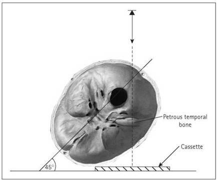
Petrous bone: anterior oblique (Stenver’s)
Position of patient and cassette
• The patient may be prone or may be more comfortable being examined erect and facing a vertical Bucky.
• The middle of the supra-orbital margin on the side being examined is centred to the middle of the Bucky.
• The neck is flexed so that the nose and forehead are in contact with the table and the orbito-meatal line is perpendicular to the table.
• From a position where the median sagittal plane is perpendicular to the table, the head is rotated toward the side under examination, such that the median sagittal plane is now at an angle of 45 degrees to the table. This brings the petrous part of the temporal bone parallel to the cassette.
• The neck is extended so that the orbito-meatal line is raised five degrees from horizontal.
• An 18 X 24-cm cassette is placed transversely in the Bucky and is centred at a level to coincide with the central ray.
Direction and centring of the X-ray beam
• A 12-degree cephalad beam angulation is employed, i.e. at an angle of seven degrees to the orbito-meatal plane, to separate the occiput from the petrous bone.
• Centre midway between the external occipital protuberance and the external auditory meatus furthest from the cassette.
• Collimate to the mastoid and petrous parts of the temporal bone under examination.
Note
This projection is now more or less redundant due to the superior diagnostic capabilities of CT.



Cranium: Isocentric skull technique
Introduction
The use of the isocentric technique offers considerable advantages over the techniques described previously and will produce images of much higher quality than those produced with just a tube and Bucky or stationary grid. The reasons for this are as follows:
• The central ray and cassette are always perpendicular to each other, thus eliminating distortion.
• The patient is always supine, thus increasing comfort and efficiency of immobilization.
• The patient's head needs to be placed in only one or a limited number of positions. Positioning is then achieved by moving only the skull unit. Again, this increases patient comfort.
• Skull unit movements are very precise and the constant position of the patient's head facilitates accurate corrections to inadequately positioned radiographs.
• It is easier to reproduce images when follow-up projections are requested or to correct errors if an image needs to be repeated.
The Orbix skull unit is one of the most widely used skull units, and the descriptions of technique that follow will be based on this unit. Other manufacturers produce units with slightly different designs, and the reader is advised to consult the handbook supplied with the individual unit. It is worth noting, however, that many of the basic principles used in positioning are very similar, regardless of which unit is employed.


Basic principles of use
All positioning and tube movement is described using the following planes and lines:
• median sagittal plane;
• anthropological plane;
• anthropological baseline;
• auricular plane.
As can be seen from the pictures opposite, the skull unit consists of a tube and cassette holder mounted on an arm (known as the tube arm). This is attached via another arm, which is fastened to the ceiling (the ceiling arm). The table upon which the patient rests can also be moved, allowing a third plane of movement.
An imaginary pivot point about which the tube arm and ceiling arm rotate is known as the isocentre. When positioning, the height of the tube arm and the patient table are arranged in such a way that the isocentre sits in the middle of the anatomical area of interest. The isocentre will then remain in this position, regardless of what angulation is applied to either the tube or the ceiling arm.
Basic position
One of the advantages of isocentric skull radiography is that the positioning for the various projections undertaken is achieved from one starting position. This is known as the basic position. Once this has been achieved, the patient will remain stationary and the desired projection can be achieved simply by moving the tube arm, ceiling arm and table.
To achieve the basic position, the various tube arm and table movements are used in conjunction with the unit-centring lights to achieve the following:
• The patient lies supine on the skull unit table, with the vertex of the skull close to the top of the table. The median sagittal plane should approximate to the middle of the table. The head should rest on a dedicated foam pad skull support.
• Both the tube arm and the ceiling arm are positioned by the side of the patient, such that they are perpendicular to the median sagittal plane (see photograph). The tube arm angulation should be set to zero.
• The table is moved so that the patient’s median sagittal plane is coincident with the vertical line of the cross of positioning light on the light beam diaphragm (A on photograph).
• The patient’s infra-orbital plane should be perpendicular to the tabletop and will coincide with the vertical beam of the cross light found on the axis of the tube arm. It may be necessary to move the table along its longitudinal axis in order to achieve this. Immobilize with Velcro headbands once in this position.
• The table height may have to be raised (perhaps in conjunction with the height of the tube arm) to ensure that the centre of the cross light found on the axis of the tube arm is positioned over the external auditory meatus (B on the photograph). The table is usually used at its maximum height.
• Finally, once the above position is achieved, the millimetre positioning scales that measure table movements should be set to zero.
Once the basic position has been achieved, a basic skull series can be undertaken by making the following modifications to the basic position:

Position of skull unit for basic position

Positioning lights for achieving the basic position

Positioning for occipito-frontal 20-degree projection

Positioning for half-axial Towne's projection

Positioning for lateral projection
Occipito-frontal projection
• From the basic position the table is moved down 40-60 mm (depending on the head size) along its longitudinal axis, such that the positions of cross lights on the light beam diaphragm move superiorly in relation to the patient's head.
• Confine the beam to the size of the head using the iris collimator.
• The tube is now positioned under the patient's head in the postero-anterior position. To achieve this, the ceiling arm will have to be moved so that it is parallel to the median sagittal plane. This allows the tube arm to swing round into the correct position. Once this has been achieved, the ceiling arm is returned to its original position by the right side of the patient.
• A 10-degree caudal angulation will be applied for an 20- degree occipito-frontal projection, zero-degree caudal angulation will be used for a 10-degree occipito-frontal projection, and a 10-degree cranial angulation will be used for an occipitofrontal projection. (Remember that the anthropological baseline is used in isocentric skull radiography. This is deviated from the orbito-meatal base line by 10 degrees.)
Half-axial, reverse Towne's
projection
• Position as above, except that a 40-degree cranial angulation is applied with the tube arm in the postero-anterior position.
• The resulting image will be free from the distortion evident when using non-isocentric techniques.
Lateral
• From the basic position, the table is moved down 40-60 mm (depending on the head size) along its longitudinal axis, such that the positions of cross lights on the light beam diaphragm move superiorly in relation the patient's head.
• Swing the ceiling arm round through 90 degrees, such that it is parallel with the median sagittal plane.
• The tube arm is now moved 90 degrees, such that the central ray will be perpendicular to the median sagittal plane. It can be rotated in either direction, so a left or right lateral can be obtained. It is preferable, however, to arrange the cassette on the side of the patient's head that is closest to the injury.
• Confine the beam to the size of the head using the iris collimator.
In all of the projections described, ensure that the cassette holder is moved as close as possible to the patient's head before exposure. This will minimize magnification (unless a degree of magnification is desired).