
Thorax: pharynx and larynx
Plain radiography is requested to investigate the presence of soft-tissue swellings and their effects on the air passages, as well as to locate the presence of foreign bodies or assess laryngeal trauma. Tomography, computed tomography (CT) and/or magnetic resonance imaging (MRI) may be needed for full evaluation of other disease processes.
It is common practice to take two projections, an anteroposterior and a lateral, using a 24 X 30-cm cassette.
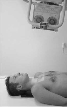
Antero-posterior
Position of patient and cassette
• The patient lies supine, with the median sagittal plane adjusted to coincide with the central long axis of the couch.
• The chin is raised to show the soft tissues below the mandible and to bring the radiographic baseline to an angle of 20 degrees from the vertical.
• The cassette is centred at the level of the fourth cervical vertebra.
Direction and centring of the X-ray beam
• Direct the central ray 10 degrees cephalad and in the midline at the level of the fourth cervical vertebra.
• Exposure is made on forced expiration.
Essential image characteristics
• The beam should be collimated to include an area from the occipital bone to the seventh cervical vertebra.
Notes
• Image acquisition may be made either with or without a Bucky grid.
• Assessment of possible small foreign bodies may not require the antero-posterior projection, as such foreign bodies are likely to be obscured by virtue of the overlying cervical spine.
• Air in the pharynx and larynx will result in an increase in subject contrast in the neck region. This may be reduced using a high-kilovoltage technique.

Antero-posterior radiograph showing normal larynx
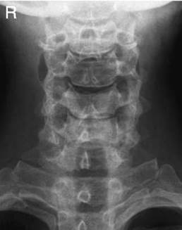
Antero-posterior radiograph of larynx showing a laryngocoele

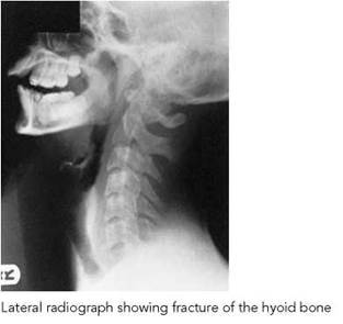
Lateral
Position of patient and cassette
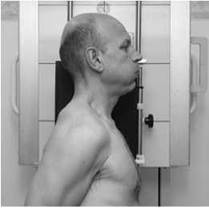
• The patient stands or sits with either shoulder against a vertical cassette. Two 45-degree pads may be placed between the patient's head and the cassette to aid immobilization.
• The median sagittal plane of the trunk and head are parallel to the cassette.
• The jaw is raised slightly so that the angles of the mandible are separated from the bodies of the upper cervical vertebrae.
• A point 2.5 cm posterior to the angle of the mandible should be coincident with the vertical central line of the cassette.
• The cassette is centred at the level of the prominence of the thyroid cartilage opposite the fourth cervical vertebra.
• Immediately before exposure, the patient is asked to depress the shoulders forcibly so that their structures are projected below the level of the seventh cervical vertebra.
• When carrying out this manoeuvre, the head and trunk must be maintained in position.
• Exposure is made on forced expiration.
Direction and centring of the X-ray beam
• The horizontal central ray is directed to a point vertically below the mastoid process at the level of the prominence of the thyroid cartilage through the fourth cervical vertebra.
Essential image characteristics
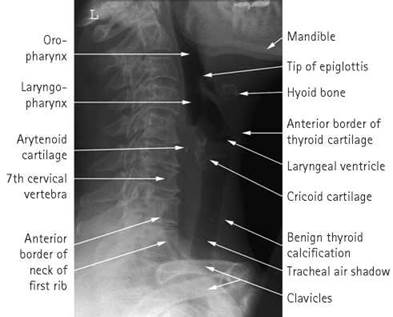
• The soft tissues should be demonstrated from the skull base to the root of the neck (C7).
• Exposure should allow clear visualization of laryngeal cartilages and any possible foreign body.
Radiological considerations
• If the prevertebral soft tissues at the level of C4-C6 are wider than the corresponding vertebral body, then soft-tissue swelling can be diagnosed (this may be the only sign of a lucent foreign body). This sign may be mimicked if the neck is flexed or may be masked if the projection is oblique. A true lateral is therefore essential.
• The cartilages of the larynx typically calcify in a patchy fashion and may mimic foreign bodies.
Thorax: trachea (including thoracic inlet)
Plain radiography is requested to investigate the presence of soft-tissue swellings in the neck and the upper thorax and to demonstrate the effects on the air passages, e.g. the presence of retrosternal goitre.
Consideration should also be given to the fact that radiography in the lateral position will involve exposure of the neck and the relatively thicker upper thorax. A high-kilovoltage technique should therefore be employed to demonstrate the full length of the trachea on one image.
Two projections, an antero-posterior and a lateral, are taken using a moving grid technique. A cassette size is selected that will include the full length of the trachea.
CT or tomography of the trachea may be required for more complex problems.

Antero-posterior
Position of patient and cassette
• The patient lies supine, with the median sagittal plane adjusted to coincide with the central long axis of the imaging couch.
• The chin is raised to show the soft tissues below the mandible and to bring the radiographic baseline to an angle of 20 degrees from the vertical.
• The cassette is centred at the level of the sternal notch.
Direction and centring of the X-ray beam
• Direct the vertical ray in the midline at the level of the sternal notch.
• Exposure is made on forced expiration.
Essential image characteristics
The beam should be collimated to include the full length of the trachea.
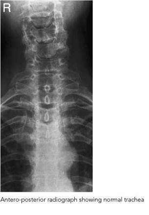
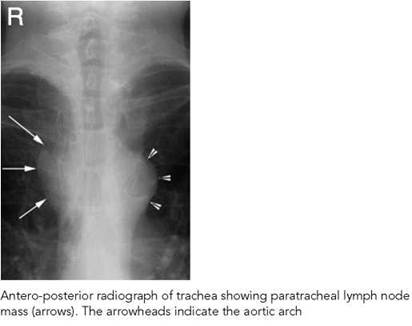

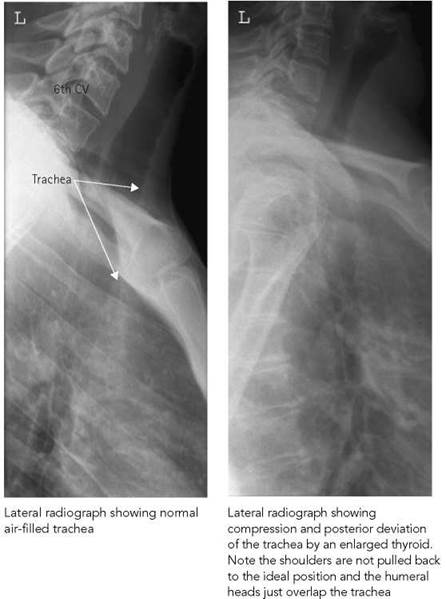
Image acquisition is best performed with the patient erect, thus enabling the patient to position the shoulders away from the area of interest.
Position of patient and cassette
• The patient stands or sits with either shoulder against a vertical Bucky.
• The median sagittal plane of the trunk and head are parallel to the cassette.
• The cassette should be large enough to include from the lower pharynx to the lower end of the trachea at the level of the sternal angle.
• The shoulders are pulled well backwards to enable the visualization of the trachea.
• This position is aided by the patient clasping their hands behind the back and pulling their arms backwards.
• The cassette is centred at the level of the sternal notch.
Direction and centring of the X-ray beam
• The horizontal central ray is directed to the cassette at the level of the sternal notch.
• The exposure is made on forced expiration.
Note
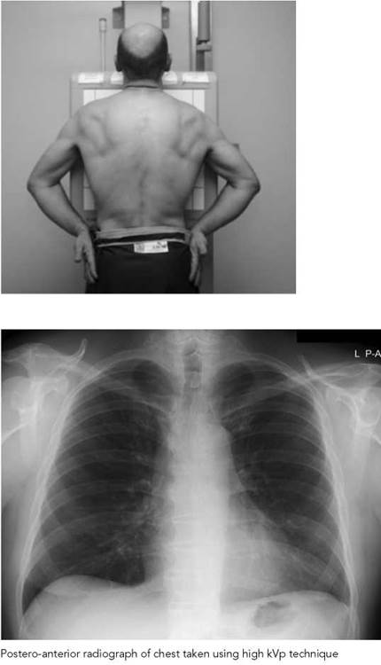
The full length of the trachea can be demonstrated on a single image using a high-kilovoltage technique (p. 29), which reduces the contrast between the neck and the denser upper thorax.
Radiological considerations
• This projection is sometimes helpful in confirming retrosternal extension of the thyroid gland. Most assessments of the trachea itself will be by bronchoscopy and/or CT (especially multislice CT with MPR reconstructions and virtual bronchoscopy).
• An anterior mediastinal mass (e.g. retrosternal thyroid) causes increased density of the anterior mediastinal window. This can also be mimicked by superimposed soft tissue if the patient’s arms are not pulled backwards sufficiently away from the area of interest.
Lungs
Introduction
Radiographic examination of the lungs is performed for a wide variety of medical conditions, including primary lung disease and pulmonary effects of diseases in other organ systems. Such effects produce significant changes in the appearance of the lung parenchyma and may vary over time depending on the nature and extent of the disease.
Imaging may also be performed using a variety of imaging modalities, notably CT and radionuclide imaging.
Recommended projections
Examination is performed by means of the following projections:


Positioning
The choice of erect or decubitus technique is governed primarily by the condition of the patient, with the majority of patients positioned erect. Very ill patients and patients who are immobile are X-rayed in the supine or semi-erect position (see Section 12). With the patient erect, positioning is simplified, control of respiration is more satisfactory, the gravity effect on the abdominal organs allows for the disclosure of the maximum area of lung tissue, and fluid levels are defined more easily with the use of a horizontal central ray.
The postero-anterior projection is generally adopted in preference to the antero-posterior because the arms can be arranged more easily to enable the scapulae to be projected clear of the lung fields. Heart magnification is also reduced significantly compared with the antero-posterior projection.
This projection also facilitates compression of breast tissue with an associated reduction in dose to the breast tissue. Additionally, the dose to the thyroid is reduced.
The mediastinal and heart shadows, however, obscure a considerable part of the lung fields, and a lateral radiograph may be necessary in certain situations.
Supplementary projections may be required for specific indications at the request of a clinician or radiologist (see table above).

Introduction
Respiration
Images are normally acquired on arrested deep inspiration, which ensures maximum visualization of the air-filled lungs. The adequacy of inspiration of an exposed radiograph can be assessed by the position of the ribs above the diaphragm. In the correctly exposed image, it should be possible to visualize either six ribs anteriorly or ten ribs posteriorly.
A brief explanation to the patient, along with a rehearsal of the procedure, should ensure a satisfactory result. Respiratory movements should be repeated several times before the performance is considered to be satisfactory. With the patient having taken a deep breath, a few moments should be allowed to elapse to ensure stability before the exposure is made. Risk of movement is minimal by using equipment capable of using exposures in the region of 20 ms. On inspiration, there is a tendency to raise the shoulders, which should be avoided, as the shadows of the clavicles then obscure the lung apices.
A normal nipple may be visible projected over the lower part of one or both lung fields on a frontal radiograph, typically having a well-defined lateral border with an indistinct medial border. In cases of doubt, a simple metallic marker can be taped to the nipple and a repeat radiograph performed. If the opacity corresponds to the metal marker, then it is likely to be nipple. This may be confirmed further by an expiratory radiograph to show that both marker and opacity move together with respiration. Due to the radiation dose involved, these additional exposures should be made under the guidance of a radiologist. Soft-tissue artefacts are discussed on p. 494.

Introduction (contd)
Image acquisition
Radiography of the lung fields may be performed by a variety of imaging techniques. The following systems are available:
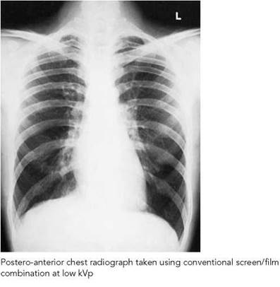
• conventional screen - film with low kVp
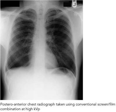
• conventional screen - film with high kVp
• conventional screen - film with selective filter device
• asymmetric screen - film system
• digital acquisition using storage phospors
• digital acquisition using semiconductor technology
• digital scanning with selenium detectors.
Selection of the imaging system to be used will be dependent on the operational protocols of the imaging department. However, the overriding objective of the system selected is to acquire an image of the thorax that will demonstrate all of the anatomical structures present, including lung parenchyma behind the mediastinum and in the regions of the costophrenic angles where the lung fields may be obscured by abdominal structures.
The following table illustrates the optimum high- and low- contrast resolution criteria expected of an imaging system where the entrance surface dose for a standard patient is 0.3 mGy using a conventional screen-film system.
|
High contrast |
Low contrast |
|
|
Small, round details |
0.7 mm diameter |
2 mm diameter |
|
Linear and reticular details |
0.3 mm width |
2 mm width |
Imaging parameters
For adults, a vertical chest stand with a stationary or moving grid is selected for patients who are able to stand unaided. Imaging without a grid is selected when a low-kVp technique is preferred.
The technique is modified when examining children and babies or examining adults whose medical condition is such that they require to be examined using mobile or portable equipment.
The following table illustrates the parameters necessary to provide optimum and consistent image resolution and contrast.
|
Item |
Comment |
|
Focal spot size |
≤1.3 mm |
|
Total filtration |
≥3.0 mm Al equivalent |
|
Anti-scatter grid |
R = 12; 40/cm |
|
Film-screen combination |
Speed class 200-400 |
|
FFD |
180 (range 140-200) cm |
|
Radiographic voltage |
100-150 kVp |
|
Automatic exposure control |
Chamber selected - lateral |
|
Exposure time |
<20 ms |
|
FFD, focus-to-film distance |
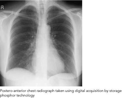


Introduction
Choice of kilovoltage/dual-energy subtraction
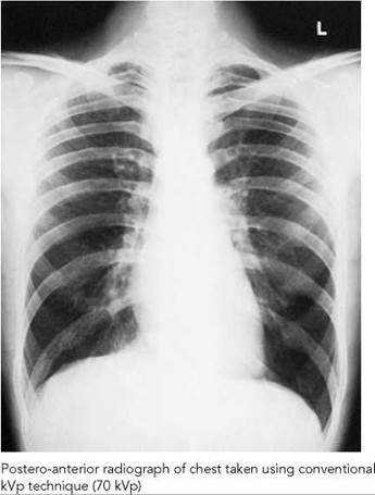
Selection of an appropriate kilovoltage should primarily provide adequate penetration from the hila to the periphery of the lung fields and should be in keeping with the patient thickness, habitus and pathology. In general, 60-70 kVp provides adequate penetration for the postero-anterior projection, in which case there will be minor penetration of the mediastinum and heart. An increase in kilovoltage is necessary for penetration of the denser mediastinum and heart to show the lung behind those structures and behind the diaphragm, as well as the lung bases in a very large or heavy-breasted patient.
A high-kilovoltage technique (120-150 kVp), appropriate to the film speed, reduces the dynamic range of information that needs to be recorded, thus enabling visualization of the lung fields and mediastinum with one exposure. This technique also has the advantage of reducing radiation dose. However, with this technique there is a loss of subject contrast and therefore visualization of small lesions of soft-tissue density becomes difficult. Additionally, rib lesions are more difficult to visualize adequately using a high-kilovoltage technique.
A range of kilovoltages (80-100 kVp) midway between nongrid and high kilovoltages is used to compromise between the advantages and disadvantages of the two techniques.
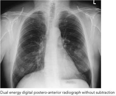
Dual-energy digital subtraction can be used to overcome the problem of pathology obscured by overlying bones. In this technique, high- and low-energy images are acquired less than 200 ms apart during the same breath-hold. The low-energy image is subtracted from the standard high-kVp image to produce bone and soft-tissue images. Three images are presented for viewing, similar to those shown opposite. Typically, there is up to 80 kVp separating the exposures.
Maintaining general contrast/use of grid
Scattered radiation has the effect of reducing subject contrast and adding image noise. To combat these effects, especially when using a high-kVp technique, selection of a grid with a grid ratio of at least 10:1 is necessary. For dedicated Bucky work, a grid designed to work at a focus-to-film distance (FFD) of 180 cm with a ratio of 12:1 is usually selected.
Grids with a lower grid ratio need less precise grid alignment and may be used for mobile radiography.
Air-gap technique
This technique employs the displacement of the subject from the film by a distance of 15 cm. To reduce any geometric unsharpness, the FFD is increased to 300 cm. A high proportion of oblique scattered radiation from the subject will no longer fall on the film because of the increased distance between subject and the film. A patient support, which is 15 cm in front of the cassette, is used to steady the patient and provide the subject-to-film distance.
Introduction (contd)
Magnification factor and focus-to-film distance
To obtain minimal magnification of the intra-thoracic structures, especially the heart, and structural detail at differing distances from the film, FFDs in the range of 150-180 cm are selected. However, the FFD must be kept constant for any one department to allow comparison of successive films. At these distances, geometric unsharpness is greatly reduced. The selection of the focal spot size is governed by the maximum output of the generator, which enables the shortest exposure time to be selected for the examination at the kilovoltage set. Ideally, the focal spot size should be no greater than 1.3 mm for an FFD of 180 cm.
An FFD less than those recommended increases the image magnification. However, such a reduction in distance to 120 cm is a satisfactory means of obtaining a short exposure time when using low-output machines such as conventional mobile units.
Exposure time related to subject movement
Involuntary subject movement is reduced by the selection of the shortest exposure time available, preferably in the millisecond range. Ideally, exposure times should be less than 20 ms. This can be obtained with high-output units at the higher mA settings, balanced to the speed of the film and screen combination and the kilovoltage selected. The use of rare earth screens and fast film combinations is essential to ensure short exposure times.
With high kilovoltage, shorter exposure times are also possible, with the added advantage of selecting a smaller focal spot within the tube rating.
Uniformity
Automatic exposure control and use of automatic processors, which are monitored for constant performance, enable films to be obtained of comparable good quality over a period of time at each repeat examination. However, even without automatic exposure control, comparable good-quality films can be obtained for the same patient by the adoption of a technique that relates kVp to chest thickness. This technique will also improve the possibility of greater uniformity throughout the range of patients.
If, for an average 22.5 cm thickness, for example, 67.5 kVp is judged to give the required penetration and density at a selected mAs factor, then for each 1 cm difference in measured thickness, a 2-3 kVp adjustment is added either as the thickness increases or as the thickness decreases.
A record of exposure factors, used for each projection, should be made on either the X-ray request card or the computer records. Reference to these records will enable films of comparable good quality to be obtained over a period of time and in different sections of the same imaging department or hospital.

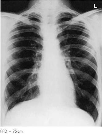

Postero-anterior radiograph of chest using asymmetrical film/screen combination
Introduction
Radiation protection
An adjustable rectangular diaphragm is used to collimate the radiation field to the size of the lung fields. This reduces the radiation dose to the patient. The effects of back-scatter from walls can be reduced by suspending a piece of lead rubber on the rear of the chest stand immediately behind the cassette holder or vertical Bucky.
For all projections of the thorax, an adjustable mobile lead protective screen or waist lead-rubber apron should be placed to shield the trunk below the diaphragm from the tube aspect.
The radiation dose to the sternum and mammary glands is minimized by employing, where possible, the postero-anterior projection of the chest in preference to the antero-posterior projection.
Film/intensifying screen combinations
Intensifying screens are selected that enable the production of good-quality radiographs that are free of movement unsharpness and quantum mottle. The radiation dose to the patient can be reduced considerably by selecting a 200-400-speed film/ screen combination. Faster speed systems, although reducing patient dose, have the disadvantage of introducing quantum mottle.
The use of asymmetrical films and screens may also be employed to record large differences in absorption on one film. Such systems are comprised of two screens differing in speed and spatial resolution and an asymmetrical dual-emulsion film with built in anti-crossover technology. The front high-resolution screen and high-contrast emulsion records the lung fields, while the faster rear screen and film emulsion records the mediastinum, retro-cardiac and subdiaphragmatic areas. This combination provides high-exposure latitude and a fast-speed system.
A major necessity in maintaining good-quality radiographs is the assurance of good film/screen contact to eliminate unsharpness. Cassettes should be tested for this as well as inspecting them for damage around the hinges and corners. Intensifying screens should be cleaned regularly in accordance with the manufacturer's instructions.
Identification
Accurate identification of chest radiographs is essential, with information such as right and left sides, patient's name, date, hospital number and radiology identification number being distinguished clearly. Congenital transposition of the organs occurs in a small number of people, and without the correct side marker the condition may be misdiagnosed. Additional information relating to orientation of the patient and tube different from the norm should also be recorded.
Radiographic anatomy
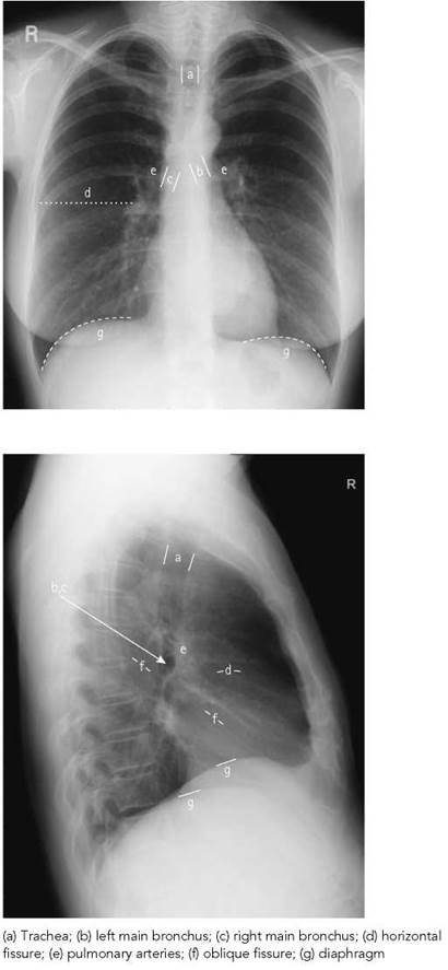
The lungs lie within the thoracic cavity on either side of the mediastinum, separated from the abdomen by the diaphragm. The right lung is larger than the left due to the inclination of the heart to the left side. In normal radiographs of the thorax, some lung tissue is obscured by the ribs, clavicles and, to a certain extent, the heart, and also by the diaphragm and upper abdominal organs in the postero-anterior projection.
The right lung is divided into upper, middle and lower lobes, and the left lung is divided into upper and lower lobes. The fissures that separate the lobes can be demonstrated in various projections of the thorax, when the plane of each fissure is parallel to the beam. On a postero-anterior radiograph, however, the main lobes overlap, so that for descriptive purposes the lungs are divided into three zones separated by imaginary horizontal lines. The upper zone is above the anterior end of the second ribs, the midzone is between the second and fourth ribs anteriorly, and the lower zone is below the level of the fourth ribs. On a lateral radiograph, where horizontal and oblique fissures are visible, upper, middle and lower lobes can be defined separately. On a postero- anterior radiograph, a horizontal fissure separating the upper and middle lobes may be seen extending from the right hilum to the level of the right sixth rib laterally. An accessory lobe called the azygos lobe is sometimes seen in the right upper zone as a result of aberrant embryological migration of the azygos vein to the normal medial position. The azygos vein, surrounded by a double layer of visceral and parietal pleura, is seen as opacity at the lower end of the accessory fissure, resembling an inverted comma.
The trachea is seen centrally as a radiolucent air-filled structure in the upper thorax, which divides at the level of the fourth thoracic vertebra into the right and left main bronchi. The right main bronchus is wider, shorter and more vertical than the left, and as a result inhaled foreign bodies are more likely to pass into the right bronchial tree. The main bronchi enter the hila, beyond which they divide into bronchi, bronchioles and, finally, alveolar air spaces, each getting progressively smaller.
As these passages are filled with air, they do not appear on a normal radiograph of the thorax, since the surrounding lung is also air-filled. If the parenchyma is consolidated, however, an air-filled bronchogram is shown.
The hilar regions appear as regions of increased radio-opacity and are formed mainly by the main branches of the pulmonary arteries. The lung markings that spread out from the hilar regions are branches of these pulmonary arteries, and are seen diminishing in size as they pass distally from the hilar regions. The right dome of the diaphragm lies higher than the left, due mainly to the presence of the liver on the right. The costophrenic angles and lateral chest walls should be defined clearly.
Special landmarks that may be seen, although not in every image, are the subclavian vein over the apex of the left lung and the inferior vena cava appearing as a triangular shadow within the cardiophrenic angle of the right lung. Both appear as low-density shadows, as does the hair-like line of the fissure between the upper and middle lobes of the right lung.
Viewing radiographs of lung fields
Apart from antero-posterior projections, all other radiographs are viewed as if the observer was looking towards the X-ray tube.
General observations
The chest X-ray (CXR) examination is a vital part of the investigation of many lung and cardiac conditions, often providing a diagnosis or the clue to the next appropriate test. The CXR is complex and not easy to read, but a high-technical quality examination with appropriate exposure on a modern film-screen combination can provide a wealth of initial detail about the heart, mediastinum and thoracic cage, as well as the lung parenchyma and pulmonary vessels.
The amount of information available to the reader, and thereby the diagnostic usefulness of the test, can be reduced by a variety of technical errors and problems. Many radiographs are initially read and acted upon by non-radiologists, who may be less aware of the diagnostic limitations of a poor-quality examination. The aim is, therefore, to demonstrate the intra-thoracic organs as fully as possible, though some areas (e.g. retrocardiac) will always be partially obscured.
Inspiration
Sub-maximal inspiration has several potential effects:
• The heart will swing up to a more horizontal lie and may thus appear enlarged.
• The lung bases will be less well inflated, which may simulate a variety of pathologies or cause abnormal areas to lie hidden.
• Under-inflation of the lower lobes causes diversion of blood to the upper lobe vessels, mimicking the early signs of heart failure.
Supine position
This posture is sometimes the best that can be achieved in a sick patient, but it alters the appearance of some structures; these are detailed in the relevant sections.
Semi-erect projection
The degree to which the patient is leaning from the vertical in such a projection varies according to circumstances, e.g. age, fitness, location of patient, availability of assistance. The patient may also lean to one side or the head may droop over the upper chest. It will be more difficult to ensure that the central ray is at right-angles to the film. The viewer will have difficulty assessing how much allowance to make for posture and technical factors; for these reasons, a supine film (being more standardized) is regarded by some radiologists as preferable to the semi-erect radiograph.
Antero-posterior projection
Magnification makes heart size difficult to assess in this projection.
Rotation
Obliquity causes the side of the chest furthest removed from the film plane to appear enlarged and hypodense, whilst the other side is partially obscured by the spine and more dense. A thoracic scoliosis may produce similar artefacts. The differing densities may simulate either abnormal density (e.g. consolidation or pleural effusion) on one side or abnormal lucency (e.g. emphysema, air-trapping) on the other.
General radiological considerations
Rotation markedly affects the appearance of the mediastinum and hila. The hilum of the raised side appears more prominent and may simulate a mass. The other hilum is hidden by the spine, tending to obscure any mass that may be present. Difficulty in assessing the mediastinum in the emergency setting is especially critical when evaluating a possible thoracic aortic aneurysm.
Lordosis
An apical lordotic projection is a useful image for a clearer depiction of the apices, but lordotic projection on an anteroposterior radiograph obscures more of the posterior basal part of the lung.
Exposure (See pp. 200 and 201.)
• Overexposed films reduce the visibility of lung parenchymal detail, masking vascular and interstitial changes and reducing the conspicuity of consolidation and masses. Pneumothorax becomes harder to detect.
• Underexposure can artificially enhance the visibility of normal lung markings, leading to them being interpreted wrongly as disease (e.g. pulmonary fibrosis or oedema).
• Underexposure also obscures the central areas, causing failure to diagnose abnormalities of the mediastinum, hila and spine.
Collimation
Good collimation is essential to good practice and dose reduction. Excessive collimation will exclude areas such as the costophrenic sulci (which may be the only site to indicate pleural disease). Failure to demonstrate the whole of the rib cage may lead to missed diagnosis of metastases, fractures, etc. (this is especially important in patients with unexplained chest pains). Collimating off the apices can obscure early tuberculosis (TB), apical (Pancoast) tumours, and small pneumothoraces.
Soft-tissue artefacts
Soft-tissue artefacts are a common cause of confusion. One of the commonest of these is the normal nipple, diagnosis of which is discussed on p. 199. Other rounded artefacts may be produced by benign skin lesions such as simple seborrhoeic warts and neurofibromata. Dense normal breast tissue or breast masses may also cause confusion with lung lesions. Breast implants may be obvious as a density with a thin curved line at the edge of the implant. Linear artefacts may be due to clothing or gowns, or in thin (often elderly) patients due to skin folds and creases. These are usually easy to spot, but they may be mistaken for the edge of the lung in a pneumothorax. Absence of soft tissue, as for example with a mastectomy, will produce hypertransradiancy of the ipsilateral thorax, although the lung itself is normal.
Postero-anterior - erect
A 35 X 43-cm or 35 X 35-cm cassette is selected, depending on the size of the patient. Orientation of the larger cassette will depend on the width of the thorax.
Position of patient and cassette
• The patient is positioned facing the cassette, with the chin extended and centred to the middle of the top of the cassette.
• The feet are paced slightly apart so that the patient is able to remain steady.
• The median sagittal plane is adjusted at right-angles to the middle of the cassette. The shoulders are rotated forward and pressed downward in contact with the cassette.
• This is achieved by placing the dorsal aspect of the hands behind and below the hips, with the elbows brought forward, or by allowing the arms to encircle the cassette.
Direction and centring of the X-ray beam
• The horizontal central beam is directed at right-angles to the cassette at the level of the eighth thoracic vertebrae (i.e. spinous process of T7), which is coincident with the lung midpoint (Unett and Carver 2001).
• The surface marking of T7 spinous process can be assessed by using the inferior angle of the scapula before the shoulders are pushed forward.
• Exposure is made in full normal arrested inspiration.
• In a number of automatic chest film-changer devices, the central beam is centred automatically to the middle of the film.
Essential image characteristics
The ideal postero-anterior chest radiograph should demonstrate the following:
• Full lung fields with the scapulae projected laterally away from the lung fields.
• The clavicles symmetrical and equidistant from the spinous processes and not obscuring the lung apices.
• The lungs well inflated, i.e. it should be possible to visualize either six ribs anteriorly or ten ribs posteriorly.
• The costophrenic angles and diaphragm outlined clearly.
• The mediastinum and heart central and defined sharply.
• The fine demarcation of the lung tissues shown from the hilum to the periphery.
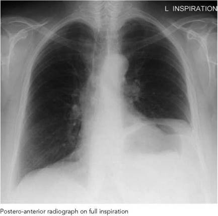
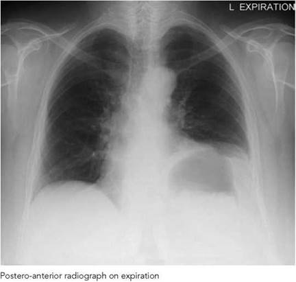
Expiration technique
A radiograph may be taken on full expiration to confirm the presence of a pneumothorax. This has the effect of increasing intrapleural pressure, which results in the compression of the lung, making a pneumothorax bigger. The technique is useful in demonstrating a small pneumothorax and is also used to demonstrate the effects of air-trapping associated with an inhaled foreign body obstructing the passage of air into a segment of lung, and the extent of diaphragmatic movement.

Common faults and remedies
• The scapulae sometimes obscure the outer edges of the lung fields. If the patient is unable to adopt the basic arm position, then the arms should be allowed to encircle the vertical Bucky.
• Rotation of the patient will result in the heart not being central, thus making assessment of heart size impossible. Attention to how the patient is made to stand is essential to ensure that they are comfortable and can maintain the position. The legs should be well separated and the pelvis symmetrical in respect to the vertical Bucky.
• The lung fields sometimes are not well inflated. Explanation and rehearsal of the breathing technique before exposure is therefore essential.
Radiological considerations
• All comments in the general section apply.
• Soft tissues: in large patients, overlying soft tissue at the bases (obesity or large breasts) obscures detail of the lung bases and pleura as well as giving unnecessary radiation to the breast. This can be made worse by many of the factors outlined above. For diagnostic reasons and for dose reduction, female patients may hold their breasts out of the main field.
• In thin patients, skin folds can produce linear artefacts, which could mimic pleural fluid or even pneumothorax. Creasing of the skin against the Bucky or cassette should be avoided.
Notes
• Careful patient preparation is essential, with all radio-opaque objects removed before the examination.
• When an intravenous drip is in situ in the arm, care should be exercised to ensure that the drip is secured properly on a drip stand before exposure.
• Patients with underwater-seal bottles require particular care to ensure that chest tubes are not dislodged, and the bottle is not raised above the level of the chest.
• A postero-anterior clip-type marker is normally used, and the image is identified with the identification marker set to the postero-anterior position. Care should be made not to misdiagnose a case of dextracardia.
• Long, plaited hair may cause artefacts and should be clipped out of the image field.
• Reduction in exposure is required in patients suffering from emphysema.
• For images taken in expiration, the kilovoltage is increased by five when using a conventional kilovoltage technique.
Radiation protection
The patient is provided with a waist-fitting lead-rubber apron, and the radiation beam is restricted to the size of the cassette.
Antero-posterior - erect
This projection is used as an alternative to the postero-anterior erect projection for elucidation of an opacity seen on a postero-anterior, or when the patient's shape (kyphosis) or medical condition makes it difficult or unsafe for the patient to stand or sit for the basic projection. For the latter, the patient is usually supported sitting erect on a trolley.
Position of patient and cassette
• The patient may be standing or sitting with their back against the cassette, which is supported vertically with the upper edge of the cassette above the lung apices.
• The median sagittal plane is adjusted at right-angles to the middle of the cassette.
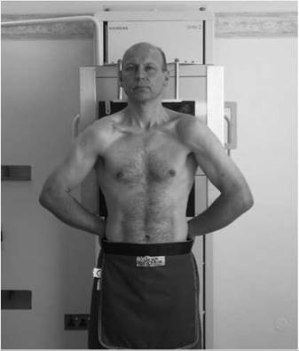
• The shoulders are brought downward and forward, with the backs of the hands below the hips and the elbows well forward, which has the effect of projecting the scapulae clear of the lung fields.
• In the unwell patient, it may not be possible to perform this procedure, with the result that the scapulae may be rotated and superimposed on the lateral chest margins. This causes an increase in radiation absorption, making it difficulty to observe underlying lung tissue. In this situation, it is preferable that the patient's arms are rotated laterally and supported with the palms of the hands facing forward. In this position, the scapulae are superimposed on the lungs but the effect of absorption is less, and comparison of either side of the upper lateral segments of the lung is made easier.
Direction and centring of the X-ray beam
• The horizontal ray is directed first at right-angles to the cassette and towards the sternal notch.
• The central ray is then angled until it is coincident with the middle of the cassette. This has the effect of confining the radiation field to the film, thus avoiding unnecessary exposure of the eyes.
• The exposure is taken on normal full inspiration.
Notes
• The use of a lower centring point combined with a horizontal beam has the undesirable effect of projecting the clavicles above the apices of the lungs.
• The radiograph opposite is of similar appearance to that of the postero-anterior chest radiograph described on p. 206. However, this projection is valuable in elucidation of relative positions of opacities seen on a postero-anterior projection.
• Small lesions previously obscured by a rib may also be demonstrated.

Radiological considerations
• This projection moves the heart away from the film plane, increasing magnification and reducing the accuracy of assessment of heart size (in this projection, a cardiothoracic ratio (CRT) of greater than 50% does not necessarily indicate cardiomegaly).
Antero-posterior - supine
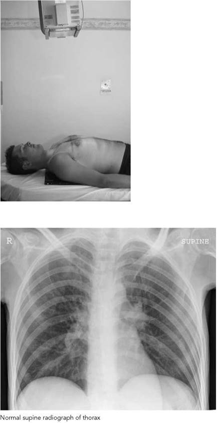
This projection is selected when patients are unable to either stand or sit for the projections described previously. The patient is usually lying supine on a trolley or bed.
Position of patient and cassette
• With assistance, a cassette is carefully positioned under the patient's chest with the upper edge of the cassette above the lung apices.
• The median sagittal plane is adjusted at right-angles to the middle of the cassette, and the patient's pelvis is checked to ensure that it is not rotated.
• The arms are rotated laterally and supported by the side of the trunk. The head is supported on a pillow, with the chin slightly raised.
Direction and centring of the X-ray beam
• The central ray is directed first at right-angles and towards the sternal notch.
• The central ray is then angled until it is coincident with the middle of the film, thus avoiding unnecessary exposure to the eyes.
Notes
• The exposure is taken on full normal inspiration.
• An FFD of at least 120 cm is essential to reduce unequal magnification of intra-thoracic structures.
• In this projection, maximum lung demonstration is lost due to the absence of the gravity effect of the abdominal organs, which is present in the erect position.
• Images of heavy breasts are not readily diffused.
Radiological considerations
• Compared with the postero-anterior projection, this projection moves the heart away from the image receptor plane, increasing magnification and reducing the accuracy of assessment of heart size (in this projection, a CTR of greater than 50% does not necessarily indicate cardiomegaly).
• The normal biomechanics of blood flow are different from those in the erect position, producing relative prominence of upper-lobe vessels and mimicking the signs of heart failure.
• Pleural fluid will layer against the posterior chest wall, producing an ill-defined increase attenuation of the affected hemithorax rather than the usual blunting of the costo-phrenic angle; fluid levels are not seen.
• A pneumothorax, if present, will be located at the front of the chest in the supine position. Unless it is large, it will be more difficult to detect if a lateral horizontal beam image is not employed.
Antero-posterior - semi-erect
This semi-recumbent position is adopted as an alternative to the antero-posterior erect projection when the patient is too ill to stand or sit erect without support.
Position of patient and cassette
• The patient is supported in a semi-recumbent position, facing the X-ray tube. The degree to which they can sit erect will depend on their medical condition.
• A cassette is supported against the back, using pillows or a large 45-degree foam pad, with its upper edge above the lung fields.
• Care should be taken to ensure that the cassette is parallel to the coronal plane.
• The median sagittal plane is adjusted at right-angles to, and in the midline of, the cassette.
• Rotation of the patient is prevented by the use of foam pads.
• The arms are rotated medially, with the shoulders brought forward to bring the scapulae clear of the lung fields.
Direction and centring of the X-ray beam
• The central ray is directed first at right-angles to the cassette and towards the sternal notch.
• The central ray is then angled until it is coincident with the middle of the film, thus avoiding unnecessary exposure to the eyes.
Notes
• Difficulties sometimes arise in positioning the cassette parallel to the coronal plane, with the resultant effect that the image of the chest is foreshortened.
• The use of a horizontal central ray is essential to demonstrate fluid levels, e.g. pleural effusion. In this situation, the patient is adjusted with the chest erect as much as possible. The horizontal central ray is directed at right-angles to the middle of the cassette. The clavicles in the resultant image will be projected above the apices.
• If the patient is unable to sit erect, fluid levels are demonstrated using a horizontal ray with the patient adopting the lateral decubitus or dorsal decubitus position.
• Sick patients may be unable to support their own head in the erect position, resulting in superimposition of the chin over the upper thorax. Care should be taken to avoid or minimize this if at all possible as apical lesions will be obscured.
Radiological considerations
An assessment of the cardiac configuration to identify individual chamber enlargement is essential, even if there is an increase in overall magnification due to shorter FFD associated with some low-powered mobiles. It is important, therefore, that the patient is not rotated.

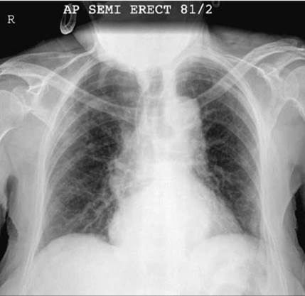
Normal semi-erect radiograph of thorax. The chin is just superimposed on the upper thorax (see notes)

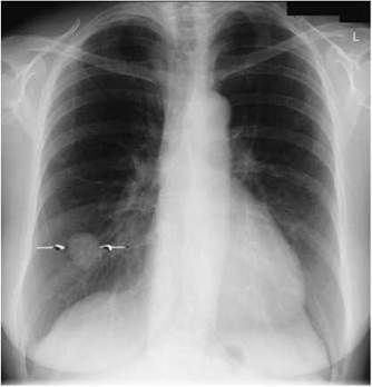

Postero-anterior and lateral radiographs of same patient showing a tumour in the right lower lobe
Lateral
A supplementary lateral projection may be useful in certain clinical circumstances for localizing the position of a lesion and demonstrating anterior mediastinal masses not shown on the postero-anterior projection. Lateral radiographs, however, are not taken as part of a routine examination of the lung fields, because of the additional radiation patient dose.
A moving or stationary grid may be used to prevent excess secondary radiation reaching the film. The FFD may be reduced to 150 cm to maintain a short exposure time.
Position of patient and cassette
• The patient is turned to bring the side under investigation in contact with the cassette.
• The median sagittal plane is adjusted parallel to the cassette.
• The arms are folded over the head or raised above the head to rest on a horizontal bar.
• The mid-axillary line is coincident with the middle of the film, and the cassette is adjusted to include the apices and the lower lobes to the level of the first lumbar vertebra.
Direction and centring of the X-ray beam
• Direct the horizontal central ray at right-angles to the middle of the cassette at the mid-axillary line.
Radiological considerations
• Insufficient elevation of the arms will cause the soft tissues of the upper arms to obscure the lung apices and thoracic inlet, and even the retrosternal window, leading to masses or other lesions in these areas being missed.
• Rotation will also partially obscure the retrosternal window, masking anterior mediastinal masses. It will also render the sternum less distinct, which may be important in the setting of trauma when sternal fracture may be overlooked.
Apices
Opacities obscured in the apical region by overlying ribs or clavicular shadows may be demonstrated by modification of the postero-anterior and antero-posterior projections.
Direction and centring of the X-ray beam
• With the patient in the position for the postero-anterior projection, the central ray is angled 30 degrees caudally towards the seventh cervical spinous process coincident with the sternal angle.
• With the patient in the position for the antero-posterior projection, the central ray is angled 30 degrees cephalad towards the sternal angle.
• With the patient reclining, and the coronal plane at 30 degrees to the cassette, to enable the nape of the neck to rest against the upper border of the cassette, the central ray is directed at right-angles to the film towards the sternal angle. Alternatively, if the patient is unable to recline 30 degrees, the technique is adapted, with the patient reclining 15 degrees and the tube angled 15 degrees cephalad.
Apices
Opacities obscured in the apical region by overlying ribs or clavicular shadows may be demonstrated by modification of the postero-anterior and antero-posterior projections.
Direction and centring of the X-ray beam
• With the patient in the position for the postero-anterior projection, the central ray is angled 30 degrees caudally towards the seventh cervical spinous process coincident with the sternal angle.
• With the patient in the position for the antero-posterior projection, the central ray is angled 30 degrees cephalad towards the sternal angle.
• With the patient reclining, and the coronal plane at 30 degrees to the cassette, to enable the nape of the neck to rest against the upper border of the cassette, the central ray is directed at right-angles to the film towards the sternal angle. Alternatively, if the patient is unable to recline 30 degrees, the technique is adapted, with the patient reclining 15 degrees and the tube angled 15 degrees cephalad.


Upper anterior region - lateral
This technique may be required to demonstrate an anterior lesion and the associated relationship of the trachea.
Position of patient and cassette
• The patient is positioned with the median sagittal plane parallel to the cassette, which is centred at the level of the shoulder of the side under examination.
• Both shoulders are drawn backward and the arms extended to move the shoulders clear of the retrosternal space.
• The hands are clasped low down over the buttocks.
Direction and centring of the X-ray beam
• Direct the horizontal central ray at right-angles to the cassette to a point immediately in front of the shoulder nearest the tube.
• Collimate to the area of interest.
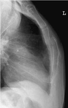
Lateral projection of upper anterior chest in a patient with a sternal fracture

Lordotic
This technique may be used to demonstrate right middle-lobe collapse or an inter-lobar pleural effusion. The patient is positioned to bring the middle-lobe fissure horizontal.
Position of patient and cassette
• The patient is placed for the postero-anterior projection.
• Then clasping the sides of the vertical Bucky, the patient bends backwards at the waist.
• The degree of dorsiflexion varies for each subject, but in general it is about 30-40 degrees.
Direction and centring of the X-ray beam
• The horizontal ray is directed at right-angles to the cassette and towards the middle of the film.

Lordotic postero-anterior radiograph showing middle lobe collapse

Introduction
Radiography of the heart and aorta is a common examination. It is performed in the routine investigation of heart disease and to assess heart size and the gross anatomy of the major blood vessels. Examination is also performed following pacemaker insertion to determine the position of the electrode leads.
The radiographic technique used is similar to that described for the lungs, and the student is referred to this section (p. 198).
Imaging may also be performed using a variety of other modalities, notably echocardiography and radionuclide imaging, with angiography performed routinely to assess the heart chambers and coronary vessels. Multidetector CT and MRI are likely to be used increasingly in the future.
Examination is performed by means of the following projections:

Anatomy
The heart is a hollow muscular organ that, together with the roots of the great vessels, is enclosed in a fibroserous sac, the pericardium. It is situated mainly to the left of the midline in the lower anterior part of the chest and attached to the central tendon of the diaphragm.
The heart has four chambers: the right and left atria and the right and left ventricles. The atria are separated by the interatrial septum and the ventricles are separated by the interventricular septum. Blood flows from the right atrium into the right ventricle through the tricuspid valve, and from the left atrium to the left ventricle through the mitral valve. The right ventricle outflow is via the pulmonary valve, and the left ventricle outflow is via the aortic valve. By rhythmic contractions, the heart serves as a pump to maintain the movement of blood throughout the circulatory system of blood vessels. At rest, there are approximately 60-80 beats per minute, with the average heart cycle occupying a time period of 0.8 s. The right side of the heart serves to perfuse the pulmonary circulation, while the left side perfuses the systemic circulation, the latter being a higher- pressure system.
The aorta, the largest of the great vessels, consists of three parts: the ascending aorta, the arch and the descending aorta, which commences at the level of the fourth thoracic vertebra.
The superior vena cava opens into the upper part of the right atrium, draining the upper limbs and head and neck. The inferior vena cava gives venous drainage from the lower limbs and abdomen, entering the inferior part of the right atrium.

Radiographically, the heart is seen as a pear-shaped structure of soft-tissue density, with its apex and inferior wall adjacent to the diaphragm and its narrower upper base overlying the spine. The size and shape of the heart vary with the build of subject, with respiration, and with the position and the clinical state of the patient.

Heart and aorta
Anatomy
Radiographic anatomy
In the postero-anterior radiograph of the chest seen opposite, features of the heart and associated vessels have been outlined and labelled.
The aortic knuckle is shown as a rounded protrusion slightly to the left of the vertebrae and above the heart shadow. The prominence of the aortic knuckle depends upon the degree of dilation or unfolding of the aorta and the presence (or absence) of cardiac disease. It also alters shape as a result of deformities in the thorax, intrinsic abnormalities and with old age. Calcification in the arch, when present, is demonstrated as curvilinear opacities.
a, superior vena cava
b, ascending thoracic aorta
c, right atrium
d, inferior vena cava
e, left subclavian vein
f, aortic knuckle
g, main pulmonary artery
h, left ventricle.
Cardiothoracic ratio
The size of the heart is estimated from the postero-anterior radiograph of the chest by calculating the CRT. This is the ratio between the maximum transverse diameter of the heart and the maximum width of the thorax above the costophrenic angles, measured from the inner edges of the ribs. In adults, the normal CRT is maximally 0.5. In children, however, the CRT is usually greater.

where a = right heart border to midline, b = left heart border to midline, and c = maximum thoracic diameter above costophrenic angles from inner borders of ribs.

Postero-anterior
A 35 X 43-cm or 35 X 35-cm cassette is selected, depending on the size of the patient. Orientation of the larger cassette will depend of the size of the patient.
Position of patient and cassette
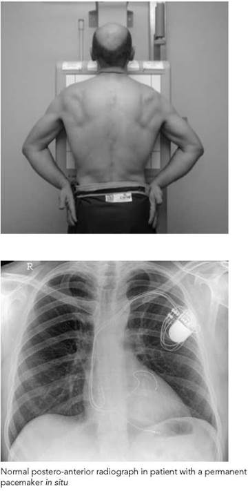
• The patient is positioned erect, facing the cassette and with the chin extended and resting on the top of the cassette.
• The median sagittal plane is adjusted perpendicular to the middle of the cassette, with the patient's arms encircling the cassette. Alternatively, the dorsal aspects of the hands are placed behind and below the hips to allow the shoulders to be rotated forward and pressed downward in contact with the cassette.
• The thorax must be positioned symmetrically relative to the film.
Direction and centring of the X-ray beam
• The horizontal central beam is directed at right-angles to the cassette at the level of the eighth thoracic vertebrae (i.e. the spinous process of T7).
• The surface markings of the T7 spinous process can be assessed by using the inferior angle of the scapula before the shoulders are pushed forward.
• Exposure is made on arrested full inspiration.
Essential image characteristics
The ideal postero-anterior chest radiograph for the heart and aorta should demonstrate the following:
• The clavicles symmetrical and equidistant from the spinous processes.
• The mediastinum and heart central and defined sharply.
• The costo-phrenic angles and diaphragm outlined clearly.
• Full lung fields, with the scapula projected laterally away from the lung fields.
Notes
• A postero-anterior marker is normally used to identify the right or left side of the patient. Care should be made to select the correct marker so as not to misdiagnose a case of dextrocardia.
• The kilovoltage selected is adjusted to give adequate penetration, with the bodies of the thoracic vertebrae just visible through the heart (see p. 201).
• For comparison purposes, records of exposure factors used, including FFD, should be kept for follow-up examinations.
• Care should be taken with postoperative patients with underwater seals and with intravenous drips. These should not be dislodged, and the examination time should be kept to a minimum.
• Underwater-seal drain bottles must be kept below the lowest point of the patient's chest at all times to prevent the contents of the bottle being siphoned back into the chest.

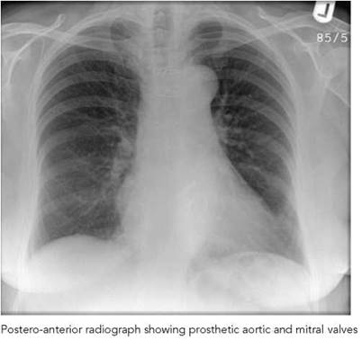
Postero-anterior
Radiological considerations
• An artefactual increase in the apparent size of the heart may be produced by a number of factors, including:
- poor inspiration, as the heart rotates up into a more horizontal orientation;
- short FFD due to geometric magnification;
- supine posture due to a more horizontal cardiac orientation and reduced FFD.
To prevent the clinician making an erroneous diagnosis of car- diomegaly or heart failure, these factors should be avoided if possible.
• If the patient is not truly erect, there may be diversion of blood flow to the upper lobe vessels, mimicking the upper- lobe blood diversion seen in heart failure.
• Following pacemaker insertion, the clinician may wish to check that the wire is located properly and to exclude complications such as pneumothorax and pleural effusion.
• Pacemaker wires and prosthetic valves are visualized less readily on low-kVp and underexposed films. A penetrated radiograph may help to demonstrate these fully. The lateral projection is also acquired to help in localization.
• Native valve and coronary artery calcifications will be seen less well on an inadequately penetrated radiograph.

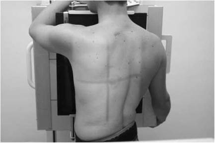
Left lateral
A left lateral image is acquired using a 35 X 43-cm cassette using a grid technique to prevent excess secondary radiation reaching the film.
Position of patient and cassette
• The patient is turned to bring the left side in contact with the cassette.
• The median sagittal plane is adjusted parallel to the cassette.
• The arms are folded over the head or raised above the head to rest on a horizontal bar.
• The mid-axillary line is coincident with the middle of the film, and the cassette is adjusted to include the apices and the inferior lobes to the level of the first lumbar vertebra.
Direction and centring of the X-ray beam
• Direct the central ray at right-angles to the middle of the cassette in the mid-axillary line.
• Exposure is made on arrested full inspiration.
Essential image characteristics
• The thoracic vertebrae and sternum should be lateral and demonstrated clearly.
• The arms should not obscure the heart and lung fields.
• The anterior and posterior mediastinum and heart are defined sharply and the lung fields are seen clearly.
• The costo-phrenic angles and diaphragm should be outlined clearly.
Radiological considerations
• A lateral radiograph may help to locate cardiac or pericardial masses, e.g. left ventricular aneurysm and pericardial cyst. These are assessed better by echocardiography or CT/MRI.
• Cardiac and pericardial calcification may be confirmed and its extent assessed more fully on a lateral chest radiograph.
• After pacemaker insertion, the lateral image confirms that the ventricular electrode lies anteriorly at the right ventricular apex.
Notes
• An FFD of 150 or 180 cm is selected.
• Patients who have recently had a permanent pacemaker implant should not raise their arms above their head. It is sufficient to raise the arms clear of the thorax, otherwise there is a risk of damage to the recently sutured tissues and possible dislodging of the pacemaker electrodes.
• Patients on trolleys may find it difficult to remain in the vertical position. A large wedge foam pad may be required to assist the patient to remain upright.


• Either a stationary or a moving grid may be employed. The kilovoltage selected is adjusted to give adequate penetration, with the bodies of the thoracic vertebrae, costo-phrenic and apical regions defined well.

Heart and aorta 7
Right anterior oblique
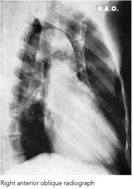
This projection is used to separate the heart, aorta and vertebral column, thus enabling the path of the ascending aorta, aortic arch and descending aorta to be acquired on a 35 X 43-cm film.
The projection will also demonstrate the diameter and the degree of unfolding of the aorta.
Position of patient and cassette
• The patient is initially positioned facing the cassette, which is supported vertically in the cassette holder with the upper edge above the lung apices.
• With the right side of the trunk kept in contact with the cassette, the patient is rotated to bring the left side away from the cassette, so that the coronal plane forms an angle of 60 degrees to the cassette.
Direction and centring of the X-ray beam
• Direct the horizontal central ray at right-angles to the middle of the cassette at the level of the sixth thoracic vertebrae, to show the heart, aortic arch and descending aorta.
Radiological considerations
• This projection may be a useful adjunct to the lateral in cases of doubt about dilatation or tortuosity of the aorta.
• This projection may be used in conjunction with a barium- swallow study to demonstrate enlargement of the heart or aorta, or abnormal vessels and vascular rings, which can produce abnormal impressions on the oesophagus and cause dysphagia.
• CT, MRI or angiography assess vascular rings more accurately.
Note
The FFD may be reduced to 150 cm.

Bones of the thorax
Introduction
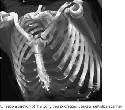
The thoracic skeleton consists of the ribs and sternum (plus the thoracic spine, which is covered in Chapter 6). The ribs and sternum may be examined radiographically in the assessment of trauma, but a good postero-anterior or antero-posterior radiograph will be more important in this setting to exclude intra- thoracic complications (e.g. pneumothorax). Many centres do not perform oblique rib views for simple trauma unless a change in management will result, and an antero-posterior or postero- anterior projection will show much of the anterior and posterior ribs that are projected above the diaphragm.
The ribs may also be examined to detect other causes of chestwall pain, e.g. rib metastases.
In cases of severe injury to the thorax, maintenance of respiratory function is of prime importance. Good postero-anterior or antero-posterior radiographs are required for full assessment of chest-wall injury, pleural changes and pulmonary damage. In cases of major trauma, damage may occur to multiple ribs, sternum, lung and thoracic spine, or any combination of these. Multiple rib and sternal fractures may result in a flail chest, where part of the chest collapses inwards during inspiration, impairing or even preventing lung ventilation. In this setting, a supine antero-posterior radiograph may be all that is attainable, and it should thus be of the highest quality possible. A pneumothorax may be obscured on a supine radiograph; in this situation, a lateral radiograph is acquired using a horizontal beam.
Injury to the lower ribs may be associated with hepatic, splenic or renal injury, and rib projections may be requested in this situation. These could be omitted if an abdominal radiograph (Section 11) is considered necessary, though ultrasound or CT may be considered more useful for assessment of possible internal organ damage.
Radiological considerations
• Pain impairs the ability of the patient to inspire deeply after rib trauma, reducing conspicuity of rib fractures and pulmonary contusion. Optimization of exposure and other factors therefore becomes more critical.
• Overexposure may allow clearer depiction of rib trauma, but it will tend to obscure associated pulmonary lesions so it should be avoided.
• Fluoroscopy may be useful to determine whether a peripheral chest lesion is real and whether it is related to a rib.

Recommended projections
|
Bones of thorax |
Trauma - trolley patients |
Antero-posterior supine chest and lateral-horizontal beam chest; other projections of chest, abdomen, ribs, sternum, thoracic vertebrae or ATLS projections on request |
|
Lower ribs |
Trauma - non-trolley patients |
Postero-anterior chest Antero-posterior (basic) Posterior oblique Other projections of chest on request |
|
Pathology |
Antero-posterior (basic) Posterior oblique |
|
|
Upper ribs |
Trauma or Pathology - non-trolley patients |
Postero-anterior chest Posterior oblique Antero-posterior first and second ribs on request |
|
Cervical ribs |
Normally demonstrated on lateral and antero-posterior cervical vertebrae Postero-anterior chest Antero-posterior cervical ribs on request |
|
|
Sternum |
Trauma - non-trolley patients |
Postero-anterior chest Anterior oblique, tube angled or Anterior oblique, trunk rotated Lateral |
|
Pathology |
Anterior oblique, tube angled or Anterior oblique, trunk rotated Lateral CT or tomography on request, according to availability |
ATLS, Advanced Trauma and Life Support; CT, computed tomography.
Lower ribs
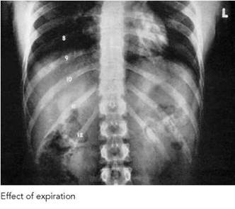
Antero-posterior (basic)
A cassette is selected that is large enough to include the whole of the right and left sides, from the level of the middle of the body of the sternum to the lower costal margin. The cassette is placed in the Bucky tray.
Position of patient and cassette
• The patient lies supine on the imaging couch, with the median sagittal plane coincident with the midline of the couch and Bucky mechanism.
• The anterior superior iliac spines should be equidistant from the couch top.
• The cassette is placed transversely, with its caudal edge positioned at a level just below the lower costal margin.
Direction and centring of the X-ray beam
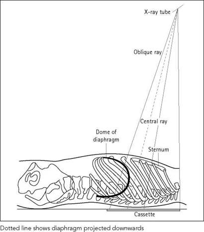
• The vertical central ray is centred in the midline at the level of the lower costal margin and then angled cranially to coincide with the centre of the film.
• This centring assists in demonstrating the maximum number of ribs below the diaphragm.
• Exposure made on full expiration will also assist in this objective.


Right and left posterior oblique
A 35 X 43-cm cassette is selected to include either the right or the left lower rib sides. The patient may be examined erect or supine using a Bucky grid.
Position of patient and cassette
• The patient lies supine on the Bucky table or stands erect, with the mid-clavicular line of the side under examination coincident with the midline of the Bucky grid.
• The trunk is rotated 45 degrees on to the side being examined, with the raised side supported on non-opaque pads.
• The hips and knees are flexed for comfort and to assist in maintaining patient position.
• The caudal edge of the cassette is positioned at a level just below the lower costal margin.
• The cassette should be large enough to include the ribs on the side being examined from the level of the middle of the body of the sternum to the lower costal margin.
Direction and centring of the X-ray beam
• The vertical central ray is directed to the midline of the anterior surface of the patient, at the level of the lower costal margin.
• From this position, the central ray is then angled cranially to coincide with the centre of the cassette.
• Exposure is made on arrested full expiration.
Notes
• The patient may find it difficult to maintain this position if they are in a great deal of pain.
• Selection of a short exposure time and rehearsal of the breathing technique may be necessary to reduce the risk of movement unsharpness.
Upper ribs
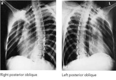
Right and left posterior oblique
Radiography may be conducted with the patient erect or supine.
A cassette is selected that is large enough to include the whole of the ribs on the side being examined from the level of the seventh cervical vertebra to the lower costal margin.
Position of patient and cassette
• The patient sits or stands with the posterior aspect of the trunk against the vertical Bucky. Alternatively, the patient lies supine on the Bucky table.
• The mid-clavicular line of the side under examination should coincide with the central line of the Bucky or table.
• The trunk is rotated 45 degrees towards the side being examined and, if supine, is supported on non-opaque pads.
• If the condition of the patient permits, the hands should be clasped behind the head, otherwise the arms should be held clear of the trunk.
• The cranial edge of the cassette should be positioned at a level just above the spinous process of the seventh cervical vertebra.
Direction and centring of the X-ray beam
• Initially, direct the central ray perpendicular to the cassette and towards the sternal angle.
• Then angle the beam caudally so that the central ray coincides with the centre of the cassette. This assists in demonstrating the maximum number of ribs above the diaphragm.
• Exposure made on arrested full inspiration will also assist in maximizing the number of ribs demonstrated.
Note
The kVp should be sufficient to reduce the difference in subject contrast between the lung fields and the heart to a more uniform radiographic contrast so that the ribs are visualized adequately in both these areas.


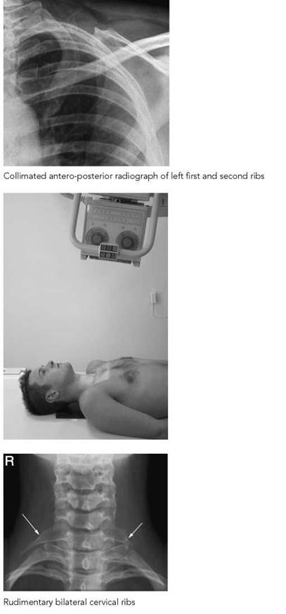
First and second - antero-posterior
The first and second ribs are often superimposed upon each other. Occasionally, a separate projection may be necessary to demonstrate them adequately.
An 18 X 24-cm or 24 X 30-cm cassette fitted with standardspeed screens is selected.
Position of patient and cassette
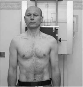
• The patient lies supine on the table or stands with the posterior aspect of the trunk against a cassette.
• When the patient is erect, the cassette is placed in a cassette holder attachment.
• The median sagittal plane is adjusted at right-angles to the cassette.
• The cassette is centred to the junction of the medial and middle thirds of the clavicle.
Direction and centring of the X-ray beam
• Direct the central ray perpendicular to the cassette and towards the junction of the medial and middle thirds of the clavicle.
Cervical - antero-posterior
Cervical ribs are normally demonstrated adequately on an anteroposterior cervical vertebrae or postero-anterior chest projection. However, occasionally a separate projection may be necessary.
A 24 X 30-cm cassette is place transversely on the Bucky tray.
Position of patient and cassette
• The patient sits or stands, with the posterior aspect of the trunk against a vertical Bucky. Alternatively, the patient lies supine on the Bucky table.
• The median sagittal plane should be at right-angles to the cassette and coincident with the midline of the table or Bucky.
• The cassette is positioned transversely in the cassette tray and should be large enough to include the fifth cervical to the fifth thoracic vertebrae
Direction and centring of the X-ray beam
• The central ray is angled 10 degrees cranially from the perpendicular and is directed towards the sternal notch.
Sternum
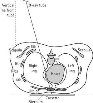
Anterior oblique - tube angled
This projection may be performed with the patient prone or erect, with the sternum at a minimal distance from the image receptor to reduce geometric unsharpness. However, if the patient has sustained a major injury to the sternum, then they may not be able to adopt the prone position due to pain.
A 24 X 30-cm grid cassette fitted with standard-speed screens is selected.
Position of patient and cassette
• The patient stands or sits facing the vertical Bucky or lies prone on the table.
• The medial sagittal plane should be at right-angles to, and centred to, the cassette.
• As the central ray is to be angled across the table, the cassette is placed transversely to avoid grid cut-off.
• If the Bucky is to be used on the table, the patient should lie on a trolley positioned at right-angles to the table, with the thorax resting on the Bucky table.
• The cassette is centred at the level of the fifth thoracic vertebra.
• Immobilization will be assisted if it is possible to use an immobilization band.
Direction and centring of the X-ray beam
• The perpendicular central ray is centred initially to the axilla of either side at the level of the fifth thoracic vertebra.
• The central ray is then angled transversely so that the central ray is directed to a point 7.5 cm lateral to the midline on the same side.
Notes
• The patient is allowed to breathe gently during an exposure time of several seconds using a low mA.
• This technique diffuses the lung and rib shadows, which otherwise tend to obscure the sternum.


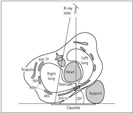
Anterior oblique - trunk rotated
A 24 X 30-cm cassette is selected for use in the Bucky mechanism. Alternatively, a grid cassette may be used in the vertical cassette holder.
Position of patient and cassette
• The patient initially sits or stands facing the vertical Bucky or lies prone on the Bucky table with the median sagittal plane at right-angles to, and centred to, the cassette.
• The patient is then rotated approximately 20-30 degrees, with the right side raised to adopt the left anterior oblique position, which will ensure that less heart shadow obscures the sternum.
• The patient is supported in position with non-opaque pads and an immobilization band where possible.
• The cassette is centred at the level of the fifth thoracic vertebra.
Direction and centring of the X-ray beam
• Direct the central ray perpendicular to the cassette and towards a point 7.5 cm lateral to the fifth thoracic vertebra on the side nearest the X-ray tube.
Note
The patient is allowed to breathe gently during an exposure time of several seconds using a low mA, provided that immobilization is adequate.


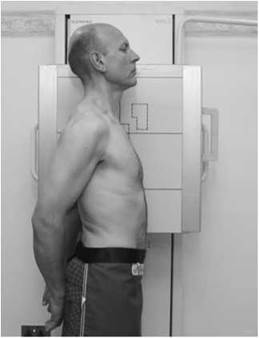
Lateral
A 24 X 30-cm grid cassette fitted with standard-speed screens is selected. Alternatively a cassette may be used in the vertical Bucky.
Position of patient and cassette
• The patient sits or stands, with either shoulder against a vertical Bucky or cassette stand.
• The median sagittal plane of the trunk is adjusted parallel to the cassette.
• The sternum is centred to the cassette or Bucky.
• The patient's hands are clasped behind the back and the shoulders are pulled well back.
• The cassette is centred at a level 2.5 cm below the sternal angle.
Direction and centring of the X-ray beam
• Direct the horizontal central ray towards a point 2.5cm below the sternal angle.
• Exposure is made on arrested full inspiration.
Notes
• Immediately before exposure, the patient is asked to pull back the shoulders.
• If the patient is standing, the feet should be separated to aid stability.
• An FFD of 120 or 150 cm is selected.
Radiological considerations
• The lateral sternal projection can be confusing, especially in elderly patients, who often have heavily calcified costal cartilages.
• Interpretation of the lateral projection is much easier when the sternum is truly lateral and at right-angles to the image receptor, with corresponding superimposition of ribs and cartilage.
• It is important to remember that the initial interpretation is often done in the emergency department by inexperienced observers; therefore, care should be exercised to ensure that the sternum is projected in the true lateral position.
• Sternal fracture, especially when there is overlap of the bone ends, may be associated with compression (wedge) fracture of the fourth to sixth thoracic vertebrae. It is appropriate to image the thoracic spine if this is suspected.
Reference

Unett EM, Carver BJ (2001). The chest X-ray: centring points and central rays - can we stop confusing our students and ourselves? Synergy November:16.
