
Benjamin Wei and Robert James Cerfolio
 Indications/Contraindications
 Robotic-assisted pulmonary lobectomy may be considered for any patient undergoing lobectomy that does not involve complex vascular or airway reconstruction, or chest wall resection. The advantage of minimally invasive chest wall resection, which avoids rib spreading but still resects ribs is controversial. In our opinion we still most commonly favor thoracotomy when chest wall resection is required. Tumors larger than 7 cm (T3), tumors crossing fissures, and centrally located tumors may all be considered for robotic lobectomy with proper patient selection and increasing surgeon experience but in general these factors disfavor a robotic approach. Similarly, radiologic evidence of N1 nodes, induction chemotherapy and/or radiation, calcified lymph nodes, and prior thoracic surgery are not contraindications to robotic lobectomy but a robotic approach should not be selected early in one’s learning curve.
The typical contraindications for lobectomy that apply to patients undergoing resection via thoracotomy would also apply to patients undergoing robotic lobectomy (e.g., prohibitive lung function or medical comorbidities, multistation N2, gross N2 disease, or evidence of N3 disease). Patients with Pancoast tumors, tumors with extensive invasion into the mediastinum or esophagus, and contraindications to general anesthesia or single-lung ventilation are also poor candidates for robotic lobectomy. In addition, small nodules that are not tissue diagnosed that require lung palpation for wedge resection are considered by some as a contraindication for robotic lobectomy when a completely portal technique is used because of the inability to palpate the lung but lung palpation is possible with a robotic technique when a robotic-assisted technique is used. However, we have used navigational bronchoscopy with methylene blue tattooing of the nodules to help guide wedge resection or a robotic lymph node dissection and then conversion to VATS.
 PREOPERATIVE PLANNING
Preoperative evaluation including pulmonary function testing should be obtained. We routinely obtain stress testing to assess for myocardial ischemia especially in patients who have had a significant smoking history. Complete patient-specific staging should also be performed prior to lung resection. This includes PET-CT scan in most patients and the selective use of brain MRI or CT (those who are symptomatic or who have large central adenocarcinomas), endobronchial ultrasound-guided fine-needle aspiration (EBUS-FNA), esophageal ultrasound-guided fine-needle aspiration (EUS-FNA) for biopsy of the posterior-inferior lymph nodes and adrenals, and/or mediastinoscopy depending on the tumor size and institutional experience.
When robotic techniques are used special considerations for robotic proficiency are needed as we have previously described—(add my reference of teaching robotics). These include documented scores of 70% or higher on simulator exercises, certificate of robotic safety training and cockpit awareness, weekly access to the robot, training of the entire personnel including the bedside assistant and familiarity with the robotic and the instruments, and a mandatory mastery of the pulmonary artery from both an anterior and posterior approach.
 SURGERY
As with any operation, planning each stage of the operation is crucial to ensure success. This begins with operating room setup when a robot is used. The robot adds anxiety to inexperienced robotic surgeons and anesthesiologists. Thus, planning of the room layout prior to the operation is critical. This includes the positioning of the bedside cart, the robot, the nurses’ table, the monitors, and the patient relative to the anesthesia equipment as needed. Because the robot is driven in over the patient’s head during lobectomy, the need for two monitors and the distance between the operating surgeon at the console and the scrub nurse and surgical assistant(s) who stand at the patient’s bedside, careful planning and communication is also needed.
Certain concepts specific to operating with robotic assistance should be mentioned here:
The insertion of robotic instruments deserves special attention as does the passing of vascular staplers around fragile structure such as the pulmonary artery and/or vein. Carefully orchestrated moves and clear communication is needed between the bedside assistant and the surgeon. We have developed our own communication system between the bedside assistant and the surgeon to prevent iatrogenic injuries. This uses the anvil of the stapler as the hour hand of a clock and the degree of articulation is also quantified and communicated.
Robotic instruments should be initially inserted under direct vision during thoracic surgery for their initial placement. Once safely positioned instruments can then be quickly and safely inserted or changed for other instruments by properly using the memory feature of the robot that automatically inserts any new instruments to a position that is exactly 1 cm proximal to its latest position. However, if this feature is used it is incumbent on the surgeon to ensure that no vital structure has moved into the path of that newly placed instrument. The most common structure would be the lung.
Operating Room Configuration
One possible universal room setup employed for all types of robotic surgery including pulmonary resection is shown below in Figure 20.1.
Consoles: The surgeon console should be positioned, so that good communication with the patient-side team can be established. The da Vinci surgical system console (Intuitive Surgical; Sunnyvale, CA) contains a microphone that amplifies the voice of the surgeon to the rest of the team. The presence of a second console permits easy exchange of control between surgeon, medical student, resident, or fellow for training purposes; this second console, if used, should be located fairly close to the primary console.
Robot/bed: The approach of the robot to the patient’s side should be clear of any obstacles. The robot is driven over the patient’s head on a 15-degree angle to open up robotic arm 3 over their head and shoulder as shown in Figure 20.5A.
In addition, monitors are positioned for a clear view by both the bedside assistants and the scrub nurse.

Figure 20.1 Operating room configuration for robotic lobectomy.
Depending on the size of the room and the arrangement of immobile structures within it, the patient’s bed may need to be turned such that the patient’s head is located well away from the ventilator and anesthesia console. A long extension for the endotracheal tubing should be used if this is necessary.
As the robot is set up before driving it in over the patient’s head, robotic arm 3 should be placed on the robotic side opposite to the side of the lobectomy (e.g., if performing a right-sided lobectomy, robotic arm 3 should be located on the robot’s left when facing it).
Assistant: The assistant will be positioned on the patient’s ventral side (i.e., in front of the patient’s abdomen/chest), with a monitor opposite to them.
Scrub nurse: The scrub nurse will be positioned with their Mayo stand near or over the patient’s feet, as in conventional thoracotomy or VATS.
Patient Positioning
General anesthesia is induced and the patient is intubated with a left-sided double-lumen endotracheal tube while supine. Proper placement of the double-lumen tube is assisted greatly by the use of a flexible pediatric bronchoscope and is critical to a smooth operation because access to the patient’s head and endotracheal tube will be limited by their positioning and the presence of the robot after docking.
After the double-lumen tube is secured, the patient is positioned in lateral decubitus with the operative side up. Images of patient positioning are shown in Figure 20.2. An axillary roll is placed. We do not use an arm board, but rather place the patient with their back at the edge of the table, leaving space in front of their face to fold their arms and taking care to expose the axilla for port placement. We have used this positioning for over 17 years for our thoracotomies, but it is critical when using a four-arm robotic approach because it allows robotic arm 3 to move on a plane that is below the bed and avoid conflicts with that arm and the operative bed itself. Padding should be used around the arms and head to prevent nerve damage during the case. We use large foam pads to protect that patient’s head and arms.
This technique is easy, quick, and cheap; requires no special equipment and is reproducible. We position patients in under 10 minutes. The foam pad also helps protect the back of the patient’s head from link two of robotic arm 3. Tape should be used to secure the patient’s hips and upper body above the shoulder. The patient should be located with their flank (i.e., space between subcostal margin and iliac crest) directly over the break point of the bed, and the table should be flexed to increase the space between the ribs. A body warmer is applied to the lower body.
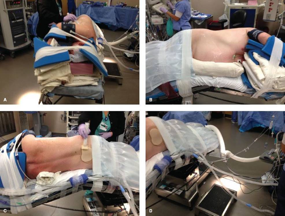
Figure 20.2 A: Patient positioning for robotic lobectomy. Foam pads for protection of pressure points of the head and arms are also shown. B: Patient positioning for robotic lobectomy. The axilla is exposed widely and the space between the patient’s iliac crest and costal margin is located above the break in the bed. C: Patient positioning for robotic lobectomy. The position of the axillary roll is shown. D: Patient positioning for robotic lobectomy, showing the distance between the anesthesia ventilator and the patient. Long flexible tubing is used to facilitate this and is taped along the bed with the other monitoring lines to provide easier access to the posterior aspect of the patient if a thoracotomy becomes necessary.
Port Placement/Docking
The ports are all inserted in the seventh intercostal space, over top of the eighth rib, for upper/middle lobectomy, and in the eighth intercostal space, over top of the ninth rib for lower lobectomy.
The ports are marked as follows: Robotic arm 3 (5-mm port) is located 1 to 2 cm lateral from the spinous process of the vertebral body, robotic arm 2 (8 mm) is 10 cm medial to robotic arm 3, the camera port (we prefer the 12-mm camera) is 9 cm medial to robotic arm 2, and robotic arm 1 (12 mm) is placed right above the diaphragm anteriorly. The assistant port (12 mm) is placed as low as possible in the chest, triangulated exactly halfway in between the most anterior robotic port (which is robotic arm 1 in the right chest and robotic arm 2 in the left chest) and the camera port and then as low as possible to remain just above the diaphragm, which is being pushed downward by the insufflating humidified CO2 gas (Fig. 20.3).
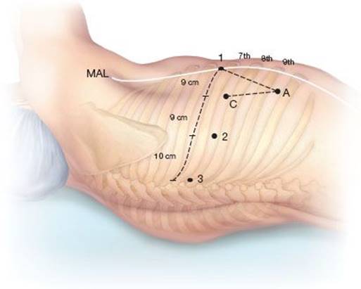
Figure 20.3 Port placement for right robotic lobectomy. C, camera port; 1, robotic arm 1; 2, robotic arm 2; 3, robotic arm 3; A, assistant port; MAL, midaxillary line.
Sequence of Port Placement
A 5-mm port is placed first in the camera port position and CO2 insufflation initiated with a pressure of 10 mm Hg. We use humidified warm CO2. An intercostal nerve block with 0.25% bupivacaine with epinephrine is then performed from ribs 3 to 8 by injecting a wheel of Marcaine subpleural under direct vision. Then the 5-mm thoracoscope is used to help assist the placement of all the other ports, which are all placed under direct vision. The camera port is placed first, robotic arm 3 is placed second, then robotic arm 2 in the right chest and robotic arm 1 in the left chest.
Then 5-mm VATS camera is then moved to the port for robotic arm 2 and the two most anterior ports (robotic arm 1 in the right chest and 2 in the left) and the access port are placed under direct vision using a seeking needle. Our techniques completely avoid all of the diaphragmatic fibers. The 5-mm camera port is then upsized to the 12-mm camera port. We use a zero-degree scope for the entire case to help prevent torquing on the intercostal nerve.
The port placement for left-sided lobectomy is a mirror image to that outlined above (Fig. 20.4). The difference is that robotic arm 3 is next to robotic arm 1, rather than robotic arm 2. The numbering is different; however, the locations of the ports are the same.

Figure 20.4 Port placement for left robotic lobectomy. C, camera port; 1, robotic arm 1; 2, robotic arm 2; 3, robotic arm 3; A, assistant port; MAL, midaxillary line.

Figure 20.5 A: Angle of approach of robot docking for lobectomy. B: View of robot docked to patient for right lobectomy. C: View of robot docked to patient for left lobectomy.
The robot is brought in at a 15-degree angle toward the patient’s face off the long axis of the bed (Fig. 20.5). The robotic arms are docked to the ports, maximizing the amount of space between the arms to avoid collisions. Once the system is docked, the OR table cannot be moved.
The instruments starting the surgery are as follows: (1) Left robotic arm—an 8-mm Cadiere grasper, (2) right robotic arm—a 8-mm bipolar curved thoracic dissector, (3) robotic arm 3—a 5-mm thoracic grasper.
Mediastinal Lymph Node Dissection
The pleural surface is inspected before initiating node dissection and lobectomy to confirm that there are no metastatic lesions.
We perform mediastinal lymph node dissection prior to lobectomy to not only evaluate the lymph nodes but also to access arterial and venous branches and the bronchus.
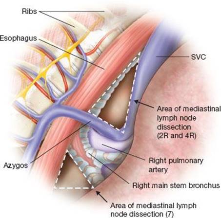
Figure 20.6 Schematic for mediastinal lymph node dissection on right-sided robotic lobectomy.
Right side—The inferior pulmonary ligament is divided to get to lymph node station 9. It is removed along with lymph node station 8. Robotic arm 3 is used to retract the lower lobe medially and anteriorly to remove lymph nodes from station 7. Care is taken to control the two feeding arteries that make the subcarinal lymph node bloody. Robotic arm 3 is used to retract the upper lobe inferiorly while robotic arms 1 and 2 are used to dissect out stations 2R and 4R, clearing the space between the SVC anteriorly, the esophagus posteriorly, and the azygos vein inferiorly (Fig. 20.6). Avoiding dissection too far superiorly can prevent injury to the right recurrent laryngeal nerve that wraps around the subclavian artery.
Left side—The inferior pulmonary ligament is divided to facilitate the removal of lymph node station 9. The nodes in station 8 are then removed. Station 7 is accessed in the space between the inferior pulmonary vein and lower lobe bronchus, lateral to the esophagus (Fig. 20.7). If still in position, the lower lobe is retracted medially/anteriorly with robotic arm 3 during this process. Retraction of the lower lobe facilitates dissection of level 7 from the left. One distinct advantage of the robot when compared to VATS is the dissection of the number 7 lymph node from the left chest. Finally, robotic arm 3 is used to wrap around the left upper lobe and pressed it inferior to allow dissection of stations 5 and 6. Care should be taken while working in the aortopulmonary window to avoid injury to the left recurrent laryngeal nerve. Station 2L cannot typically be accessed during left-sided mediastinal lymph node dissection due to the presence of the aortic arch, but the 4L node is commonly removed.
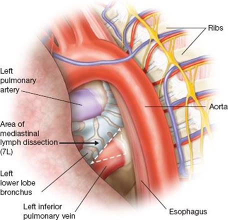
Figure 20.7 Dissection of level 7 mediastinal lymph node during left robotic lobectomy (left lower lobe in place).
General Concepts
In general, for a right-handed surgeon, a blunt instrument such as a Cadiere forceps is placed in robotic arm 2—which is always the left hand, and the right hand—which is always the robotic arm 1—uses a thoracic dissector. We prefer to place a vessel loop under the vessel to be stapled to help elevate it while the stapler is passed under it.
The stapler may be placed through one of the three ports—the access port, robotic arm 1, or robotic arm 2. The current design of commercially available white or grey vascular staplers requires a 12-mm port and for the green-loaded stapler, commonly used for the bronchus, a 15-mm port is required. We prefer to remove the trocar and leave it docked to the robotic arm and then place the stapler through the skin incision.
We commonly use a prerolled sponge to absorb blood from the operative field or facilitate blunt dissection to improve visibility.
Removal of lymph nodes from around structures should be done before stapling them in the interests of both (1) ensuring an oncologically sound operation and (2) facilitating isolation and division of structures.
If adhesions are significant they may be initially dealt with via the assistant port using VATS techniques until safe placement of all the robotic instruments is permitted.
The order in which the structures are isolated and divided during lobectomy varies somewhat depending on patient anatomy. What follows is a general outline of the typical conduct of the operation for each lobectomy.
Right Upper Lobectomy
Retraction of the right upper lobe laterally and posteriorly with robotic arm 3 helps expose the hilum.
The bifurcation between the right upper and middle lobar veins is developed by dissecting it off the underlying pulmonary artery.
The 10R lymph node between the truncus branch and the superior pulmonary vein should be removed or swept up toward the lung, which exposes the truncus branch (Fig. 20.8).
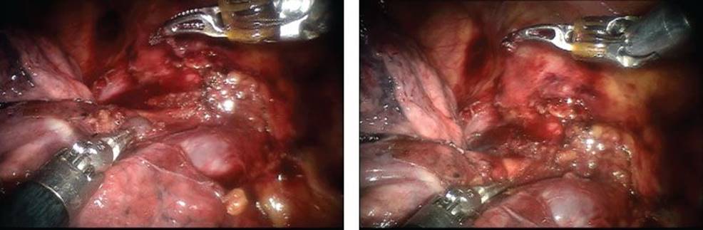
Figure 20.8 Dissection of lymph node 10R between truncus branch and right superior pulmonary vein during robotic right upper lobectomy.
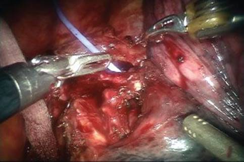
Figure 20.9 Anterior retraction of lung to exposure bifurcation of right mainstem bronchus.
The superior pulmonary vein is encircled with the vessel loop and then divided. The truncus branch is then divided.
The right upper lobe is then reflected anteriorly to expose the bifurcation of the right mainstem bronchus (Fig. 20.9). There is usually a lymph node (level 11R) here that should be dissected out to expose the bifurcation. The right upper lobe bronchus is then encircled and divided (Fig. 20.10). Care must be taken to apply only minimal retraction on the specimen to avoid tearing the remaining pulmonary artery branches.
Finally the posterior segmental artery to the right upper lobe is exposed, the surrounding N1 nodes removed, and the artery encircled and divided (Fig. 20.11).

Figure 20.10 A,B,C and D: Exposure and division of right upper lobe bronchus.
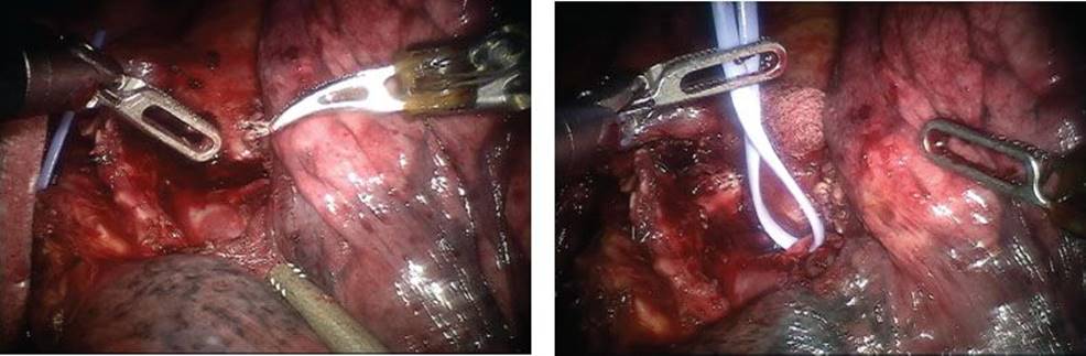
Figure 20.11 Exposure of right posterior segmental artery.
The upper lobe is reflected again posteriorly, and the anterior aspect of the pulmonary artery is inspected to make sure that there are no arterial branches remaining. If not, then the fissure between the upper and middle lobes, and the upper and lower lobes, is then divided. This is typically done from anterior to posterior but may be done in the reverse direction if the space between the pulmonary artery and right middle lobe is already developed. During completion of the fissure the right upper lobe should be lifted up to ensure that the specimen bronchus is included in the specimen.
Right Middle Lobectomy
Retraction of the right middle lobe laterally and posteriorly with robotic arm 1 helps expose the hilum.
The bifurcation between the right upper and middle lobar veins is developed by dissecting it off the underlying pulmonary artery. The right middle lobar vein is encircled and divided.
The fissure between the right middle and lower lobes, if not complete, is divided from anterior to posterior. Care should be taken to avoid transecting segmental arteries to the right lower lobe.
The right middle lobe bronchus is then isolated. It will be running from left to right in the fissure. Level 11 lymph nodes are dissected from around it. It is encircled and divided, taking care to avoid injuring the right middle lobar artery that is located directly behind it.
Dissection of the fissure should continue posteriorly until the branches to the superior segment are identified. Then the one or two right middle lobar segmental arteries are isolated and divided.
Stapling of middle lobar structures may be facilitated by passing the stapler from posterior to anterior, to have a greater working distance.
The fissure between right middle and upper lobes is then divided.
Right Lower Lobectomy
The inferior pulmonary ligament should be divided to the level of the inferior pulmonary vein.
The bifurcation of the right superior and inferior pulmonary veins should be dissected out. The location of the right middle lobar vein should be positively identified to avoid inadvertent transection.
A subadventitial plane on the ongoing pulmonary artery should be established. If the major fissure is not complete then it should be divided. The superior segmental artery and the right middle lobe arterial branches are identified. The superior segmental artery is isolated and divided. The common trunk to right lower lobe basilar segments may be taken as long as this does not compromise with the middle lobar segmental artery/arteries; otherwise, dissection may have to extend further distally to ensure safe division.
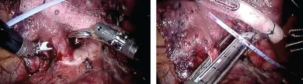
Figure 20.12 Isolating and dividing a lingular artery during robotic left upper lobectomy.
The inferior pulmonary vein is divided.
The right lower lobe bronchus is isolated, taking care to visualize the right middle lobar bronchus crossing from left to right. The surrounding lymph nodes, as usual, are dissected and the bronchus divided. If there is any question of compromising the right middle lobe bronchus, the surgeon can ask the anesthesiologist to hand ventilate the right lung to confirm that the middle lobe expands.
Left Upper Lobectomy
Retraction of the left upper lobe laterally and posteriorly with robotic arm 3 helps expose the hilum.
The presence of both superior and inferior pulmonary veins is confirmed, and the bifurcation dissected.
The lung is then reflected anteriorly with robotic arm 3 and interlobar dissection is started, going from posterior to anterior.
If the fissure is not complete then it will need to be divided. Reflecting the lung posteriorly again and establishing a subadventitial plane will be helpful. The branches to the lingula are encountered and divided in the fissure during this process (Fig. 20.12). The posterior segmental artery is also isolated and divided (Fig. 20.13). Division of the lingular artery or arteries can be done before or after division of the posterior segmental artery.
The superior pulmonary vein is isolated, then divided (Fig. 20.14). Because the superior pulmonary vein can be fairly wide, it may require that the lingular and upper division branches be transected separately.
Often the next structure that can be divided readily will be the left upper lobar bronchus, as opposed to the anterior and apical arterial branches to the left upper lobe. The upper lobe bronchus should be encircled and divided, often passing the stapler from robotic arm 1 to avoid injuring the main pulmonary artery (Fig. 20.15).

Figure 20.13 Isolating and dividing the posterior ascending artery during robotic left upper lobectomy.

Figure 20.14 Isolating and dividing the left superior pulmonary vein during robotic left upper lobectomy.
Finally, the remaining arterial branches are encircled and divided.
Left Lower Lobectomy
The inferior pulmonary ligament should be divided to the level of the inferior pulmonary vein. The lower lobe is then reflected posteriorly by robotic arm 3.
The bifurcation of the left superior and inferior pulmonary veins should be dissected out.
The lung is reflected anteriorly by robotic arm 3. The superior segmental artery is identified. The posterior ascending arteries to the left upper lobe are frequently visible from this view also. The superior segmental artery is isolated and divided. The common trunk to left lower lobe basilar segments may be taken as long as this does not compromise the middle lobar segmental artery/arteries; otherwise, dissection may have to extend further distally to ensure safe division. If the fissure is not complete, this will need to be divided to expose the ongoing pulmonary artery to the lower lobe.
After division of the arterial branches, the lung is reflected again posteriorly. The inferior pulmonary vein is divided.
The left lower lobe bronchus is isolated. The surrounding lymph nodes, as usual, are dissected and the bronchus divided.
Specimen Removal/Conclusion of Operation
The “drop zone” for the specimen should be well away from the pulmonary artery, which can be injured during this process if care is not taken. Before the bag is inserted robotic arm 3 is used to hold the specimen. The bag is inserted via the assistant port and robotic arms 1 and/or 2 are used to ensure the bag is deployed under the trocar. This ensures that the bag is opened in the right direction. Robotic arm 3 then drops the specimen in the bag and it then grasps the far lip of the bag to make sure it does not spin while robotic arms 1 and 2 are used to place the specimen in the bag. Care is taken to make sure the arms are not inside the bag.
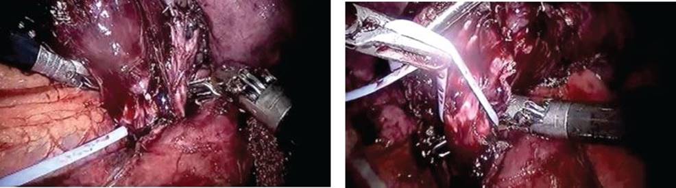
Figure 20.15 Isolating and dividing the left upper lobe bronchus during robotic left upper lobectomy.
The chest is irrigated with normal saline, the presence of air leaks checked with insufflation, hemostasis is confirmed, and a 20-Fr chest tube is placed via the most anterior port, which is robotic arm 1 in the right chest and robotic arm 2 in the left. The robotic arms are removed under direct vision with insufflation discontinued to confirm the absence of bleeding. The camera port is removed. The robot is undocked and pushed away from the patient’s bed.
The bag is removed from the body, usually after enlarging the assistant nonrobotic port posteriorly to avoid injuring the diaphragm. Our techniques completely avoid all of the diaphragmatic fibers.
The chest tube is secured with a no. 5 Ethibond suture.
The fascial layer in the 12-mm ports is closed with 0 Vicryl suture after the break is removed from the table.
The skin is closed in a knotless subcuticular fashion with 3-0 Vicryl suture.
 POSTOPERATIVE MANAGEMENT
The management of patients undergoing robotic lobectomy does not differ specifically from patients undergoing VATS lobectomy. Our patients go directly to the floor and not to the intensive care unit. Patients generally do well with patient-controlled analgesia or even oral pain medications. Chest tubes are removed when air leak resolves and at outputs of up to 450 mL/day, depending on the patient. Patients are typically discharged on postoperative day 2 or 3.
 COMPLICATIONS
The same complications that can occur after open or VATS lobectomy can occur after robotic lobectomy. We have recently reported that the incidence of chylothorax may even be slightly higher in patients undergoing robotic lobectomy, likely due to increased thoroughness of mediastinal lymph node dissection (publication in press). The incidence of atrial fibrillation, pneumonia, blood loss, and pain appear less with robotic when compared to lobectomy performed via thoracotomy and similar or favorable when compared to VATS lobectomy.
 RESULTS
Reported series of robotic lobectomy to date have been notable for a fairly low conversion rate, low mortality rate, and comparable morbidity to VATS approaches (Table 20.1). With increasing experience, operating times for robotic lobectomy have been shown to decrease; at our institution, robotic lobectomies with complete mediastinal lymph node dissection can routinely be done in 1.5 to 2 hours from incision to skin closure. The single comparison with VATS lobectomy published to date, by Louie et al., demonstrates similar blood loss, operative time, ICU stay, and length of stay between robotic and VATS but did show benefits of robotic lobectomy in terms of duration of narcotic use and time to return to usual activities. Park et al. have reported 5-year survival rates for 310 patients with stage I nonsmall cell lung cancer of ∼90% following robotic lobectomy, which is comparable to both VATS and open lobectomy. Our experience has been that robotic lobectomy facilitates a thorough mediastinal lymph node dissection, which we believe is associated with a greater accuracy of staging and therefore more optimal adjuvant treatment.
TABLE 20.1 Results Reported by Series of Robotic-assisted Lobectomies

 CONCLUSIONS
Robotic pulmonary lobectomy represents an emerging method to achieve an oncologically satisfying, minimally invasive operation that decreases perioperative risk compared to lobectomy via thoracotomy. Robotic lobectomy does seem to offer some special benefits to the surgeon in terms of lymph node dissection, ergonomics, and teachability. The need for highly trained team members who are familiar with each other and the operation cannot be underestimated for robotic pulmonary lobectomy. A systematic approach to both learning and executing the procedure is highly recommended.
Recommended References and Readings
Cerfolio RJ, Bryant AS, Minnich DJ. Starting a robotic program in general thoracic surgery: Why, how, and lessons learned. Ann Thorac Surg. 2011;91:1729–1737.
Cerfolio RJ, Bryant AS, Skylizard L, et al. Initial consecutive experience of completely portal robotic pulmonary resection with 4 arms. J Thorac Cardiovasc Surg. 2011;142:740–746.
Gharagozloo F, Margolis M, Tempesta B, et al. Robot-assisted lobectomy for early-stage lung cancer: Report of 100 consecutive cases. Ann Thorac Surg. 2009;88:380–384.
Louie BE, Farivar AS, Aye RW, et al. Early experience with robotic lung resection results in similar operative outcomes and morbidity when compared with matched video-assisted thoracoscopic surgery cases. Ann Thorac Surg.2012;93:1598–1605.
Park BJ, Flores RM, Rusch VW. Robotic assistance for video-assisted thoracic surgical lobectomy: Technique and initial results. J Thorac Cardiovasc Surg. 2006;131:54–59.
Park BJ, Melfi F, Mussi A, et al. Robotic lobectomy for non-small cell lung cancer (NSCLC): Long-term oncologic results. J Thorac Cardiovasc Surg. 2012;143:383–389.
Veronesi G, Galetta D, Maisonneuve P, et al. Four-arm robotic lobectomy for the treatment of early-stage lung cancer. J Thorac Cardiovasc Surg. 2010;140:19–25.