Jamie B. Conti
Gregory W. Woo
Temporary pacing is an essential tool in the critical care setting for providing emergent cardiac pacing. This chapter will discuss (a) indications for temporary pacing, (b) types of temporary pacemakers available, (c) techniques for placement, (d) basic troubleshooting, and (e) potential complications.
Indications
The most common indication for temporary pacing is hemodynamically unstable bradycardia. Bradycardia may be the result of primary degenerative conduction system disease or secondary causes such as medications, metabolic abnormalities, or acute myocardial infarction (AMI) (1). Medications that may cause bradycardia include antiarrhythmic drugs and β- or calcium channel blockers, in particular diltiazem or verapamil. Hyperkalemia and other electrolyte disturbances can not only cause bradycardia, but also may contribute to high pacing thresholds. Therefore, secondary causes of bradycardia must be corrected for pacing to be successful. Table 33.1 lists some indications for temporary cardiac pacing.
Not all bradycardia in the setting of AMI requires temporary pacing (Tables 33.2A and B). For example, an atrioventricular (AV) block that occurs during an inferior wall MI from a right coronary artery occlusion may be secondary to ischemia of the region supplied by the AV nodal artery. In this setting, AV block rarely progresses to high-degree AV block, typically resolves within 2 weeks, and probably will not require temporary pacing. On the other hand, AV block in the setting of an anterior wall MI carries a worse prognosis. Anterior wall MIs can be more extensive, and AV block seen in this situation is usually from infarct involvement of the interventricular septum and infranodal conduction system. AV block from an anterior wall MI may rapidly deteriorate to asystole. Temporary pacing in the setting of an anterior wall MI and complete heart block (CHB) is strongly suggested.
Other indications for temporary pacemakers are considered prophylactic. There are some procedures performed in the cardiac catheterization or electrophysiology lab in which temporary pacing is strongly considered. These patients should be evaluated carefully preoperatively, and pacing initiated as necessary. For example, a patient undergoing alcohol septal ablation has a high risk of developing acute CHB. The incidence of acute CHB has been reported to be as high as 55% to 70%, but a much smaller percentage requires permanent cardiac pacing—11% to 17% (2,3). Other examples include percutaneous coronary rotational atherectomy (Rotoblation), rheolytic thrombectomy (AngioJet), or a generator replacement in a patient who is pacemaker dependent.
Temporary pacing is also commonly used after cardiac surgery. The incidence of hemodynamically unstable bradycardia after cardiac surgery has been reported to be as high as 4% (4). Specifically, AV block is not uncommon after valvular heart surgery and is likely a result of either direct injury to the surrounding conduction system or edema. Sinus bradycardia occurs in 64% of postcardiac transplant patients (5). Though this bradycardia often resolves, temporary pacing may be required to maintain adequate heart rates for optimal cardiac output in the immediate posttransplant recovery period. In addition, temporary atrial pacing may reduce the incidence of postoperative atrial fibrillation, which is quite common after cardiac surgery (6).
Temporary pacemakers may also be used for other reasons besides bradycardia and heart block. Pause or bradycardia-dependent polymorphic ventricular tachycardia, such as that occurring in the long QT syndrome, can be treated with temporary pacing, which will shorten the QT interval. Overdrive or rapid ventricular pacing may also prevent ventricular tachycardias triggered by premature ventricular contractions. In addition, some ventricular tachycardias may be terminated by ventricular pacing. Likewise, certain atrial tachycardias, such as atrial flutter, can be terminated with rapid atrial pacing.
Temporary Pacing Catheters
Deciding on Atrial, Ventricular, or Dual-chamber Pacing
Although most intensive care unit (ICU) pacing needs can be met with single-chamber, right ventricular pacing, there are some clinical situations in which dual-chamber pacing is necessary. Some patients rely on AV synchrony and atrial contraction to maintain optimal physiologic cardiac contraction for adequate cardiac output. Such patients include those with congestive heart failure, significant diastolic dysfunction, and right ventricular infarction with AV block. Dual-chamber pacing is most readily available in postcardiac surgical patients, as temporary epicardial wires are routinely placed at the time of surgery. However, if not available, insertion of two separate pacing catheters or a specialized dual-chamber pacing catheter will be necessary. Single-chamber atrial pacing can also be used in many of the aforementioned situations, as long as the only conduction system abnormality is from sinus node dysfunction and not AV block. Also, single-chamber atrial pacing may be preferred if the patient has a mechanical tricuspid valve to avoid catheter entrapment or tricuspid valve endocarditis to avoid dislodgement of the vegetation. Table 33.3 summarizes the available pacing modes for temporary pacing.
|
Table 33.1 Indications for temporary cardiac pacing |
|||||||||||||
|
|||||||||||||
|
Table 33.2A Standard American College of Cardiology/American Heart Association classification for recommendations and indications |
|||||||||||||
|
|||||||||||||
|
Table 33.2B Indications for pacing in acute myocardial infarction |
||||||||||||||||||||||||||||||||||||||||||||||||
|
||||||||||||||||||||||||||||||||||||||||||||||||
|
Table 33.3 Common pacing modes available for temporary pacing |
||||||||||||||||||||||||||||||||||||||||||||||||
|
||||||||||||||||||||||||||||||||||||||||||||||||
Ventricular
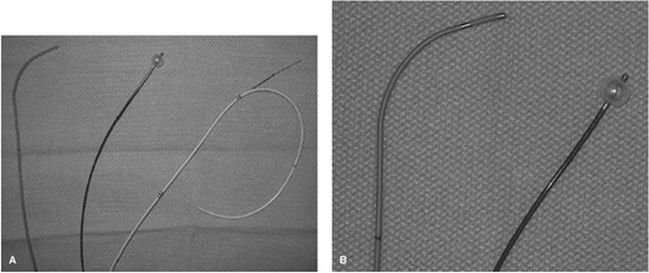
Most temporary transvenous pacing catheters are designed for placement in the right ventricle. These pacing catheters are constructed of a wire insulated with a polymer such as polyethylene or polyvinyl chloride, and are available in various sizes (Fig. 33.1A). Firmer materials add to the maneuverability of torque-controlled catheters, allowing for more control during placement and more stability once positioned. However, because of their relative stiffness, added caution must be taken during placement to avoid perforation of the great vessels or heart. In general, these catheters should be placed with fluoroscopic guidance. Balloon-tipped catheters are available to allow for flow-assisted placement, which is critical if fluoroscopy is not available (Fig. 33.1B). There are also specialized pulmonary artery catheters that have dedicated pacing ports for the placement of a pacing wire electrode while still allowing for routine hemodynamic monitoring (Fig. 33.2). However, inflation of the balloon to obtain pulmonary artery wedge pressure may cause the electrode to migrate and can result in loss of pacing capabilities.
|
|
|
Figure 33.1. A: Transvenous pacing catheters. From left to right: 6F torque-guided bipolar pacing catheter, 5F balloon-tipped pacing catheter, and 7.5F pacing Swan-Ganz pulmonary artery catheter. B: Close-up view of the tips of the torque-guided and balloon-tipped pacing catheter. |
Atrial
There are also multiple catheter designs for atrial pacing. Some pacing catheters are preformed to facilitate placement into the right atrial appendage or coronary sinus, thus allowing atrial pacing (Fig. 33.3). Other atrial pacing catheters use a delivery system consisting of a guiding catheter to position the pacing electrode catheter within the right atrium. A variety of new electrode catheters consist of several electrodes positioned 10 to 20 cm proximal to the distal-tip electrodes. These electrodes are positioned to lie along the lateral right atrial wall, allowing atrial sensing and pacing. An innovative modification of this technique allows for a small atrial J-wire to be placed through a dedicated lumen in the catheter into the right atrium, with distal electrodes already positioned in the right ventricular apex (Fig. 33.4). Both of these types of catheter adaptations have been developed to allow a “one venous stick” approach to AV pacing. However, the atrial electrodes provided by these catheters often do not reliably pace the atrium.
|
|
|
Figure 33.2. A: Swan-Ganz catheter with the pacing electrode extended out at the 20-cm mark (marked A). B: Pacing wire (marked B) inserted into a dedicated pacing port (marked A). |
The vast majority of temporary pacing catheters are designed to lie against the ventricular myocardium once positioned (passive fix). However, newer catheter designs, especially those for right atrial pacing, have a deployable screw that is embedded in the myocardium (active fix) (Fig. 33.5). All leads placed in the heart carry a risk of migration and perforation (7), but active fix leads may reduce the risk of dislodgement (8).
|
|
|
Figure 33.3. Atrial pacing catheter with a preformed “J” to facilitate placement in the right atrial appendage. OW marks the “orientation wing” to assist in the placement. A marks the proximal connectors that connect to the generator. B marks the distal preformed “J” tip. |
Temporary pacing catheters can be bipolar or unipolar. Bipolar catheters have both the negative (anode) and positive (cathode) electrodes in contact with the heart (Fig. 33.6A). In a unipolar catheter, the anode is in contact with the heart, but the cathode is elsewhere on the body (Fig. 33.6B). Bipolar electrodes are preferred because they are less susceptible to external electrical interference.
External Pacemaker Unit
The external temporary pacemaker unit controls the pacing mode, stimulus output, stimulus frequency, and threshold for sensing intrinsic activity (Fig. 33.7). Pacing modes can be synchronous (demand/inhibited) or asynchronous to pace the atrium, ventricle, or both. The range of output varies from 0 to 20 mA. The frequency can be adjusted from 30 to 180 beats per minute. Sensing threshold can be varied from no sensing (asynchronous) to less than 1.5 mV. The function of these units varies widely by manufacturer, making it imperative that staff and physicians are familiar with the routine function of the particular unit in their hospital.
|
|
|
Figure 33.4. A balloon-tipped catheter designed for placement into the right ventricular apex. A small atrial “J” electrode (designated a on the picture) can be positioned through a lumen into the right atrium. A marks the connectors for pacing the atrium. V marks the connectors for pacing the ventricle, and v is the distal electrode that is positioned in the right ventricle. |
|
|
|
Figure 33.5. An example of an active fixation lead with a screw helix. (Compliments of Medtronic, Inc., Minneapolis, MN.) |
|
|
|
Figure 33.6. Diagrams representing bipolar and unipolar pacing configurations. A: In the bipolar configuration, both the positive (cathode) and negative (anode) electrodes are in contact with the myocardium. B: In the unipolar configuration, one electrode is in contact with the myocardium. The other electrode may be a patch on the skin, or in this example the generator. |
|
|
|
Figure 33.7. Temporary pacing unit. This unit has separate controls for atrial and ventricular programming. Controls A, B, and C adjust pacing rate, atrial pacing output, and ventricular pacing output, respectively. Control D selects pacing mode, atrioventricular (AV) interval, and sensitivities. |
Assessment of the Patient
A complete patient assessment must be made prior to pacemaker placement. Bradycardia alone is not sufficient. Hemodynamic instability, symptoms, or evidence of significant conduction system disease on the electrocardiogram (bundle branch block, high-degree heart block) favors therapy. Also, reversible causes, especially medications, should be sought. Glucagon may be effective for β-blocker overdose, calcium for calcium channel overdose, and digoxin immune Fab (Digibind®) for digitalis glycoside overdose. Some bradycardias can be treated medically with agents such as isoproterenol, a β1-receptor agonist that increases heart rate. Electrolyte abnormalities such as hyperkalemia and other adverse metabolic states, such as severe acidosis, should be corrected, and in fact, if uncorrected, may make pacing ineffective.
Preparing Equipment
All the necessary equipment should be available and inspected. The external pacing unit should be programmed to the desired settings and turned to the “On” position. A new battery should be installed. The lead should be examined for any defects. The connector cables should be inserted into the pacing generator to make sure that they are compatible (Fig. 33.8).
Continuous electrocardiographic monitoring and a defibrillator at the bedside are required. Fluoroscopy is preferred, but is not mandatory, if a balloon-tipped electrode catheter is being placed through the internal jugular or subclavian vein. Having the equipment ready before temporary catheter insertion is critical to avoid complications.
Venous Access
Access is obtained using the Seldinger technique by placement of an introducer sheath that is large enough to accommodate the size of the pacing catheter (usually 4–7 French). The most common sites used are the internal jugular, subclavian, or femoral veins. The advantages and disadvantages of various access sites are given in Table 33.4. For bedside placement, the right internal jugular vein or left subclavian vein is the preferred site. In the cardiac catheterization lab, the femoral vein is commonly used. Of note, if the patient is likely to require permanent transvenous pacing, then the subclavian vein should be avoided on the side of the planned permanent implantation. Other potential sites include the basilic or cephalic veins; however, the downside is that access of these vessels usually requires a surgical cut-down approach.
|
|
||||||||||||
|
Figure 33.8. An example of a temporary pacing system setup. An inspection of the appropriate connectors, pins, and other accessories should be performed before placement. A is the generator unit. B1 and B2 are the proximal and distal ends of an extension adaptor. C shows connector pins. D shows the proximal connectors of the pacing catheter. |
||||||||||||
|
Table 33.4 Common sites for central venous access when placing a temporary pacing catheter |
||||||||||||
|
|
|
|
Figure 33.9. Evidence of ventricular capture during temporary pacing catheter placement. R denotes intrinsic ventricular conduction. F is a fusion beat. P is a paced ventricular beat. |
Placement of the Transvenous Pacing Catheter
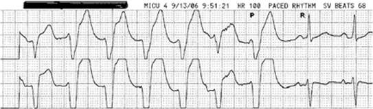
Once the sheath is in place, the pacing catheter is advanced through the sheath into the venous system. The lead is attached to the connector cables, which have been inserted into the pacing unit. The lead is gradually advanced under continuous electrocardiographic monitoring, with care not to use excessive force, as this may lead to perforation. If performed under fluoroscopic guidance, an inferior or septal position in the distal third of the apex is preferred. Apical right ventricular capture is noted by a left bundle branch, superior axis pattern. Once ventricular capture is obtained, threshold testing is performed. If no fluoroscopy is available, a balloon-tipped catheter must be used. Placement into the right ventricle is confirmed by ventricular capture on the electrocardiogram (ECG) with a left bundle branch block, superior axis pattern (Fig. 33.9). Once in place, the balloon is deflated to avoid advancement into the pulmonary artery.
Placement of a temporary atrial pacemaker should be performed by clinicians who implant permanent pacemakers, as the implant techniques are similar. Fluoroscopy is essential for this procedure.
Dual-chamber temporary pacing most commonly occurs after cardiac surgery when the patient has epicardial wires that were placed at the time of the surgery. Rarely is temporary endocardial dual-chamber pacing necessary. An example would be a patient with complete heart block and congestive heart failure who requires the hemodynamic benefit of atrioventricular synchrony and atrial contraction. In such a rare situation, separate catheters are placed, or if single access is preferred, a specialized dual-chamber pacing catheter is appropriate (Fig. 33.4).
|
|
|
Figure 33.10. Loss of capture during threshold testing. Temporary pacing rate was set at 100 bpm. Loss of capture is obvious with change in QRS morphology. P is the last paced ventricular beat. The patient's own rhythm comes through with loss of ventricular pacing. R denotes an intrinsic ventricular beat. |
Pace Sensing and Threshold Determinants
After obtaining good anatomic positioning of the pacing catheter, a stimulation threshold should be determined. With continuous electrocardiographic monitoring, pacing should begin at a rate at least 10 beats per minute faster than the patient's intrinsic heart rate, with the output set at 5 mA. The output of the pacemaker is gradually decreased until the stimuli fail to produce ventricular (or atrial) capture (Fig. 33.10). The current setting at which capture fails to occur is called the pacing threshold and should be less than 1 mA. The pacemaker output should be set at three to five times the pacing threshold.
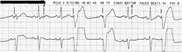
If the pacemaker is to be used in a demand mode, it is also important that there is adequate sensing of the endocardial electrogram. To ensure good sensing, the pacing rate is set lower than the patient's intrinsic rate. The sensitivity of the pacing unit is set at its most sensitive level (lowest value), and is then decreased (higher values) gradually. The setting at which the pacemaker fails to sense and begins pacing competitively with the patient's intrinsic rhythm is called the sensing threshold (Fig. 33.11). For demand pacing, the sensitivity should be set at a more sensitive level than the sensing threshold.
Postinsertion Care
The electrode catheter and its introducer should be secured to the skin under sterile conditions. Coiling the proximal electrode catheter around the insertion site and firmly taping to the skin prevents dislodgement of the distal catheter. An extension cable should be used to connect the catheter electrode pins to the pulse generator. The pulse generator should be secured to a location where it will unlikely be moved or disconnected inadvertently. The plastic shield provided with the pulse generator should be slipped over its controls to prevent accidental control movement. Covering of the entire pacemaker unit (including shield) with a plastic see-through glove prevents exposure of the generator to liquids.
|
|
|
Figure 33.11. Sensitivity testing. Temporary pacing rate was set at 60 bpm. Sensitivity level was gradually set to lowest sensitivity (highest value). Ventricular pacing occurs at intervals when pacing should have been inhibited. Pacing artifacts (indicated by vertical marks) are appreciated and are “marching through” at 60 bpm. X denotes functional noncapture that occurs because a pacing stimulus was delivered at a time when the ventricle was refractory. |
A portable chest radiograph should be obtained to ensure proper positioning of the pacing catheter and to assess for complications, particularly pneumothorax. A baseline 12-lead ECG should be obtained to document the QRS morphologic features, with the pacing catheter in proper position. A right bundle branch block morphology in lead V1 with ventricular pacing may indicate pacing of the left ventricle (via an atrial septal defect [ASD], ventral septal defect [VSD], etc.) and increases the patient's risk of a thromboembolic stroke. A change in the morphology of the paced QRS may be the first sign of electrode displacement. Continuous electrocardiographic monitoring of the patient is imperative.
Daily evaluation should include inspection of the entry site, cardiac auscultation, threshold determinations, and evaluation of intrinsic rhythm. Complications of the pacemaker often can be determined by auscultation. For example, a pericardial friction rub may indicate ventricular penetration, and a clicking sound may imply intercostal muscle stimulation. Marked changes in thresholds may occur with catheter movement or perforation, requiring catheter repositioning. Any significant changes should be evaluated with an ECG and chest radiograph. The intrinsic rhythm can be evaluated by reducing the rate of the pacemaker until the underlying rhythm emerges.
Troubleshooting
Problems will arise, and a stepwise approach to determine the problem should be taken to determine the cause. The two most common problems are failure to capture (pacing artifact without a conducted QRS) and failure to pace (no pacing artifact).
|
|
|
Figure 33.12. Ventricular undersensing. The sixth and eighth pacing artifacts occur at times when pacing should have been inhibited. |
Common reasons for noncapture usually include lead dislodgement, change in pacing threshold, or undersensing. Noncapture from lead dislodgment may simply be from lack of apposition of the catheter against tissue. However, a more concerning cause is cardiac perforation. Changes in the patient's clinical status or introduction of new medications can lead to increased pacing thresholds. Electrolyte abnormalities and acidosis may prevent pacing. Antiarrhythmic medications, especially sodium channel blockers such as flecainide or propafenone, may also increase pacing thresholds. Undersensing is failure of the pacemaker to sense intrinsic conduction (Fig. 33.12), and can appear as noncapture when a pacing stimulus is delivered during the refractory period (Figs. 33.11 and 33.12).
Failure to pace may occur due to loss of output from the pacemaker generator, break in the circuit, or oversensing. Potential causes of loss of output from the generator include loss of power (low batteries) or disconnection of the pacing catheter from the generator. Also, a break in the insulation or wiring anywhere between the connectors to the pacing catheter may result in failure to pace. Oversensing is the inhibition of the pacemaker by events that the pacemaker should ignore (Fig. 33.13), and may be caused by electromagnetic interference (EMI), T waves, and myopotentials. It is important to note that EMI is prevalent in most ICU settings.
Troubleshooting begins with a thorough review of the patient's clinical status and medications. It also includes the following steps:
· Check labs to evaluate for electrolyte abnormalities such as hyper- or hypokalemia, and correct any reversible causes of increased pacing thresholds.
· Increase the output of the generator to restore capture.
|
|
|
Figure 33.13. Ventricular oversensing. The arrow points to a time when a ventricular paced event should have occurred. |
· Review the settings on the generator box for appropriate programming and to see if the device has been turned on.
· Replace the batteries if they are suspected to be depleted.
· Inspect the box for any obvious abnormalities and examine the connectors from the generator to the pacing catheter for any loose connections, fractures, or insulation breaks.
· A chest radiograph should be part of any workup for pacing problems; it is useful to evaluate for not only lead dislodgment, but also pneumothorax.
· An echocardiogram may help in determining if there is a new effusion, which may be seen if a perforation has occurred.
A specific problem that may be encountered with dual-chamber pacing is pacemaker-mediated tachycardia (PMT). For dual-chamber pacing, the postventricular atrial refractory period (PVARP) and the AV delay must also be programmed (Fig. 33.14A). The PVARP is the time after a ventricular-sensed or paced beat when atrial activity is ignored. The PVARP prevents tracking of retrograde atrial contractions, which could lead to PMT (Fig. 33.14B). However, too long of a PVARP setting may result in loss of AV synchrony, as the intrinsic P wave will not be sensed. The AV delay is the time from an atrial-sensed or paced beat to a ventricular-paced beat. This is analogous to the PR interval on a standard electrocardiogram.
Complications
Although the insertion of a temporary transvenous pacing catheter is generally a safe and well-tolerated procedure, there are potential complications that can occur as with any invasive intervention. The potential for a complication can occur at any point during the procedure from the time of initial catheter insertion to the time that the catheter is finally removed. Complications include:
|
|
|
Figure 33.14. A, B: Schematic of postventricular atrial refractory period (PVARP) and an example of pacemaker-mediated tachycardia (PMT). AP is atrial paced; VP is ventricular paced. PVARP is the period after a ventricular event during which no atrial event will be ignored. Example of PMT that occurred in a patient with a permanent dual-chamber pacemaker. The top recording is an electrocardiogram lead; the bottom recording is a marker channel. Atrial-sensed (AS) activity occurs because of retrograde conduction after a ventricular-paced (VP) event. The pacemaker, therefore, tracks the atrial event, leading to the pacing rate at the upper tracking limit. PMT was terminated by placement of a magnet. Lengthening of the PVARP would have prevented sensing of the retrograde atrial activity. (Diagrams are compliments of Medtronic, Inc., Minneapolis, MN.) |
· Vascular injury
· Inadvertent arterial puncture
· Bleeding
· Infection
· Cardiac tamponade
· Tricuspid valve injury
· Pneumothorax
· Hemothorax
· Air embolism
· Phrenic nerve injury
· Thoracic duct injury
· Guidewire fracture
· Thromboembolism
· Atrial or ventricular arrhythmia
Insertion of a temporary pacemaker in the setting of an acute MI may increase the risk of certain complications. Bleeding risk is increased because the patient is usually anticoagulated. The infarcted myocardium may be soft and necrotic, increasing the risk of cardiac perforation. Additionally, infarcted tissue may result in high pacing thresholds or inability to capture. The myocardium may be irritable, increasing the risk of arrhythmia. Metabolic and electrolyte abnormalities may also result in high pacing thresholds or myocardial irritability, and must be corrected.
If a complication is suspected, physical exam, chest radiography, and an echocardiogram should be performed immediately. The physical exam may reveal a new pericardial friction rub, suggesting cardiac perforation. The radiograph will help to evaluate the lead location and potential cardiopulmonary complications, such as a pneumothorax or pericardial or pleural effusion. Limited echocardiogram images can quickly assess the presence of an effusion.
|
|
|
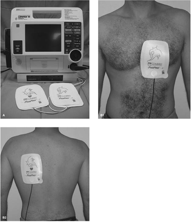
Figure 33.15. A: Defibrillator/pacemaker unit with adhesive patch electrodes. This type of system is readily available, relatively easy to operate, and has reasonable pacing reliability. However, patient discomfort limits its use. B: Typical anteroposterior patch location for transcutaneous pacing. |
Pacemaker Syndrome
One significant problem that the practitioner should be cognizant of is that of “pacemaker syndrome.” Occasionally, when temporary ventricular pacing is initiated, loss of synchrony between the atria and ventricles or retrograde activation of the atrium may result in unfavorable hemodynamic changes. These changes may cause symptoms such as dizziness, throat tightness, neck pulsations, fatigue, or dyspnea. If a patient has symptoms suggestive of “pacemaker syndrome” during temporary ventricular pacing, a dual-chamber system is strongly advised if permanent pacing is necessary.
Alternative Temporary Pacing Methods
External Noninvasive (Transcutaneous) Pacing
External transcutaneous pacing was introduced by Zoll in 1952, before other pacing techniques were developed (9). Pacing is achieved through two large, self-adhesive electrode pads, usually placed in an anteroposterior position, which are connected to an external pulse generator (Fig. 33.15A, B). Since its introduction, improvements have been made that have resulted in better stimulation thresholds and pacing reliability. Successful pacing with this method has been reported to be as high as 94% (10). However, pectoral muscle stimulation is common and may require sedation of the patient (10), and reliable capture is still not as consistent as with other pacing methods. Because external pacing does not require central venous access and is relatively easy to perform, this method is still frequently utilized as a bridge to a more reliable pacing method.
Transesophageal Pacing
Transesophageal pacing is possible because of the posterior position of the esophagus to the left atrium. The advantages of this technique are that its placement is relatively noninvasive and has minimum complications; the major disadvantage is that ventricular capture is unreliable. Therefore, transesophageal pacing is most useful for patients that need atrial pacing only. This technique requires a special transesophageal pacing electrode and generator, which provides higher outputs necessary for transesophageal pacing—usually between 2 and 530 mA (Fig. 33.16). The electrode is introduced orally or nasally, and is advanced to the proximity of the left atrium. Optimal electrode position occurs at a location with the largest atrial electrograms.
Transthoracic Pacing
A transthoracic approach has been used successfully on many occasions, but less invasive temporary pacing techniques have made this procedure quite uncommon. This highly invasive technique is performed by direct percutaneous placement of pacing catheters or wires into the right ventricle through a transthoracic needle, utilizing an approach from the precordium or from the subxiphoid region. A needle and stylet are introduced into the right ventricle. As the needle and stylet are being advanced, they are connected to the V1 lead of a standard ECG. A current of injury pattern is seen upon penetration of the right ventricular wall, providing that there is not complete ventricular asystole. Removal of the stylet and aspiration of blood verifies intracardiac positioning. The pacing catheter is then passed through the needle, the needle is removed, and the electrodes are connected to a standard pacing box. There are several complications that are potentially severe, including pneumothorax, coronary artery perforation, mediastinal bleeding, and cardiac tamponade. This approach should thus be used only when other pacing options are not available.
|
|
|
Figure 33.16. A: Temporary transesophageal pacing catheter. B: 10F (top) and 5F (bottom) catheters. (Compliments of CardioCommand, Inc., Tampa, FL.) |
Summary
Temporary pacing is an invaluable tool for the management of cardiac rhythm disturbances, including not only bradyarrhythmias, but also some tachyarrhythmias. There are multiple transvenous pacing catheters available, in addition to other modalities if temporary transvenous pacing is not possible. Basic familiarity with its indications, placement, and management is essential for all of those who work in the critical care setting.
References
1. Atkins J, Leshin S, Blomqvist C. Ventricular conduction blocks and sudden death in acute myocardial infarction. Potential indications to pacing. N Engl J Med. 1973;288(6):281–284.
2. Geitzen F, Leuner C, Raute-Kreinsen U, et al. Acute and long-term results after transcoronary ablation of septal hypertrophy (TASH). Catheter interventional treatment for hypertrophic obstructive cardiomyopathy. Eur Heart J. 1999;20(18):1342–1354.
3. Faber L, Seggewiss H, Gleichmann U. Percutaneous transluminal septal myocardial ablation in hypertrophic obstructive cardiomyopathy: results with respect to intraprocedural myocardial contrast echocardiography. Circulation. 1998;98(22):2415–2421.
4. Baerman J, Kirsh M, de Buitleir M, et al. Natural history and determinants of conduction defects following coronary artery bypass surgery. Ann Thorac Surg. 1987;44(2):150–153.
5. Miyamoto Y, Curtiss E, Kormos R, et al. Bradyarrhythmia after heart transplantation. Incidence, time course, and outcome. Circulation. 1990;82(5 Suppl.):IV313–317.
6. Daoud E, Snow R, Hummel J, et al. Temporary atrial epicardial pacing as prophylaxis against atrial fibrillation after heart surgery: a meta-analysis. J Cardiovasc Electrophysiol. 2003;14(2):127–132.
7. Cooper JP, Swanton RH. Complications of transvenous temporary pacemaker insertion. Br J Hosp Med. 1995;53(14):155–161.
8. Pinto N, Jones T, Dyamenahalli U, et al. Temporary transvenous pacing with an active fixation bipolar lead in children: a preliminary report. PACE. 2003;26(7 Pt 1):1519–1522.
9. Zoll PM. Resuscitation of the heart in ventricular standstill by external electric stimulation. N Engl J Med. 1952;247(20):768–771.
10. Madsen J, Meibom J, Videbak R, et al. Transcutaneous pacing: experience with the Zoll noninvasive temporary pacemaker. Am Heart J. 1988(1 Pt 1); 116:7–10.