George C. Velmahos
Invasive procedures are performed at the bedside of critically ill patients with increasing frequency to avoid the risks, resources, and inconvenience of transportation to other areas of the hospital (1,2). With the development of safety systems and new techniques, the morbidity of these bedside procedures is not higher than the morbidity of similar procedures performed in the operating room, emergency department, or angiography suite (3,4). Knowledge of anatomy, attention to detail, and understanding of potential pitfalls need to be mastered by the specialists involved in bedside procedures. Collaboration across specialties is crucial, as boundaries are continuously crossed and traditional turfs make little sense in the age of technology.
Below I will describe the following procedures, which can safely be performed at the bedside: open and percutaneous thoracostomy, thoracentesis, pericardiocentesis, diagnostic peritoneal aspiration and lavage, percutaneous tracheostomy, open and percutaneous cricothyroidotomy, percutaneous gastrostomy, abdominal pressure monitoring, and percutaneous vena cava filter placement (5). Routine procedures such as central venous and arterial catheterization will be described in other chapters. The described procedures are selected from a myriad of possible bedside procedures (spanning from urologic, neurosurgical, gynecologic, and general surgical to orthopedic, pediatric, or radiographic) on the basis of two criteria: they can potentially be performed not only by surgeons but also by any adequately trained physician functioning within appropriate patient safety systems, and on occasions several of these procedures must be performed emergently and without the luxury of waiting for a subspecialty expert. Therefore, critical care physicians from different tracks should familiarize themselves with the technique, indications, and complications associated with these procedures.
Tube thoracostomy
Indications
Fluid or air that remains undrained into the pleural cavity may cause infection, lung collapse, or entrapment, and therefore needs to be drained. A pneumothorax is usually drained if it exceeds 15% to 20% of the hemithoracic volume or causes hemodynamic instability (6). Smaller pneumothoraces can be observed. There is no universally-accepted volume threshold for the drainage of a hemothorax. Usually, all hemothoraces of penetrating traumatic cause are drained. Hemothorax after blunt trauma is drained if more than 200 mL of blood is in the thoracic cavity, as found by blunting of the costodiaphragmatic angle on erect chest radiograph or estimated on computed tomographic imaging. Fluids of other cause (hydrothorax, chylothorax, etc.) are drained according to volume and patient symptomatology.
Following trauma, the chest tube output is used as an indication to operation. A thoracotomy is offered if the output is more than 1,500 mL shortly after placement or if output of more than 200 mL per hour persists over 4 to 6 hours after placement (7). However, these are not absolute criteria. One must remember that chest tubes are not reliable drains of intrathoracic blood because they often clog, kink, or are misplaced. A hemodynamically unstable patient who is bleeding in the chest should be taken to the operating room even with lower than the above chest tube outputs.
Technique
Percutaneous Thoracostomy
The percutaneous technique is safe for patients who do not have risk factors for intrathoracic adhesions (e.g., previous thoracic operation, empyema, clotted hemothorax, etc.). A 28 Fr or 32 Fr chest tube is adequate according to the size of the patient and does not cause excessive pain. For the drainage of simple pneumothorax, smaller tubes (18 Fr or 22 Fr) may be used.
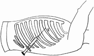
The site of placement is chosen and prepared. The most common site is at the intercostal space above the nipple (usually the fourth intercostal space) and at the midaxillary line. The diaphragm can elevate up to the nipple in expiration, and for this reason, lower placement of chest tubes is not safe and may risk injury to the diaphragm and intra-abdominal organs. Adequate local analgesia is key because tube thoracostomy is a painful procedure (Fig. 34.1). The entire track should be infiltrated and not just the subcutaneous tissue.
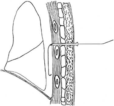
A needle, covered by a plastic sheath and connected to a fluid-filled syringe, is inserted through the skin with the intent to hit the underlying rib. Once the rib is felt, the needle is slightly withdrawn and then redirected immediately over the rib to avoid injury to the neurovascular intercostals bundle that travels under each rib. Under continuous suction the syringe and needle are slowly advanced until bubbles of air are aspirated. This indicates that the needle has entered into the pleural space. The needle and syringe are withdrawn, and the plastic sheath left in place. A guidewire is inserted into the sheath (Fig. 34.2). If there is any resistance during advancement of the guidewire, the procedure should be repeated from the beginning. With the guidewire in place, the plastic sheath is removed. A 2-cm skin incision is made, and sequential dilatation with three consecutive dilators is done over the guidewire. Following this, the chest tube, loaded on a plastic guide, is placed over the guidewire into the chest. The plastic guide and guidewire are withdrawn, and the chest tube is left in place.
|
|
|
Figure 34.1. Site for generous injection of local anesthetic prior to chest tube insertion, usually at the fourth intercostal space, above the rib margin, at midaxillary line. |
Securing the chest tube is a very important part of the procedure. The tube is tied to the skin with a 0 nonabsorbable suture. A separate suture should be placed as a purse-string around the tube and left untied. This suture will serve to close the incision once the chest tube is removed. The tube should also be taped to the skin. Extra precautions should be taken to have the chest tube and its connection to the drainage bottles secured to avoid inadvertent partial or complete removal. Usually, 20 cm H2O negative suction is applied at least for the first 48 hours although there is no evidence that this shortens the period of placement or decreases the rate of residual pneumothorax compared to water seal.
|
|
|
Figure 34.2. A guidewire is inserted through the sheath into the pleural space, guiding sequential enlargement of the tract by tapered dilators. |
|
|
|
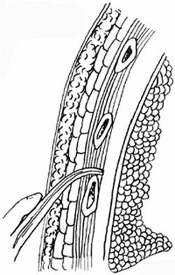
Figure 34.3. A sturdy clamp is necessary to spread the muscles wide to allow easy insertion of the chest tube. |
Open Thoracostomy
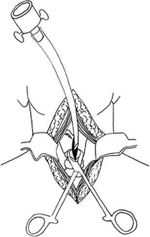
The site of placement is marked as above. A 4-cm incision is made parallel to the ribs. Blunt dissection follows through the subcutaneous tissue and muscle. The clamp is finally inserted into the pleural space in a controlled way over the rib underlying the skin incision (Fig. 34.3). It is then opened wide to spread the muscles and enlarge the tract. This is an important step since the novice tends to make the skin incision large but the intermuscular tract too small, resulting in difficulty with tube insertion. There is no reason to “tunnel” the track to the rib above the skin incision. Tunneling causes more pain, makes the procedure more difficult, and offers no benefit.
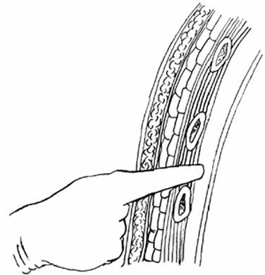
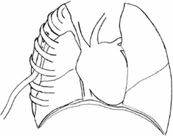
A finger is inserted to explore for the presence of adhesions at the site of insertion (Fig. 34.4). Then, the chest tube is guided by a clamp into the opening and toward the superior and posterior hemithorax (Fig. 34.5). The clamp is removed, and the tube is secured as discussed above.
Removal of Chest Tubes
Removal takes place when there is no air leak and fluid output is less than 2 mL/kg per 24 hours. The patient is asked to inspire maximally and hold the breath. With one hand against the chest wall, the physician pulls abruptly the chest tube with the other hand and immediately ties the purse string to seal the insertion site. The site is dressed. If a purse-string suture is absent, it is important to apply occlusive dressing to prevent air entry into the chest.
|
|
|
Figure 34.4. A finger is inserted into the track prior to tube insertion to ensure a clear pleural space and absence of adhesions. |
Pitfalls and Complications
A misplaced chest tube may not drain adequately. Do not assume that air or fluid will be drained because a chest tube is in place (8). Confirm correct placement with a chest radiograph, and have a low threshold to replace or add a chest tube, if the symptoms are not relieved, hemodynamic instability persists, or drain seizes abruptly. A chest tube may cause more harm than benefit if the technique is wrong. Injury to the intercostals vessels or lung may cause significant bleeding. The chest tube should then be removed and on rare occasions the bleeding site explored if the hemorrhage continues. Intraparenchymal placement may cause a persistent air leak. It is usually diagnosed by computed tomography. The tube should be removed, and the leak usually seals. The chest tubes should be securely tied and taped to the skin and checked daily. Accidental removal of a tube equals a sloppy technique. Infection is the most common related complication. Poor aseptic technique, long duration of the tube in the chest, and no antibiotic prophylaxis (one dose before tube placement) are associated with this complication (9). Significant undrained hemothorax (estimated at more than 400 mL) should be managed by thoracoscopic evacuation or intrathoracic thrombolysis (10,11).
|
|
|
Figure 34.5. The final position of the chest tube. |
Diagnostic peritoneal aspiration (DPA) and lavage (DPL)
Indications
The most common reason for a diagnostic peritoneal aspiration and lavage (DPA/DPL) is the diagnosis of intra-abdominal injury. A count of more than 100,000 red blood cells/mm3 or 500 white blood cells/mm3 or the presence of bile, enteric content, or high-amylase fluid in the effluent of the lavage are considered indications for an operation following abdominal trauma (12). However, these criteria are oversensitive and frequently lead to unnecessary operations. Furthermore, these cell counts are valid for blunt but not for penetrating trauma. Portable ultrasonography and the liberal use of helical computed tomography have limited the usefulness of DPL. Currently, DPA/DPL is used only on rare occasions due to lack of appropriate technologic resources or due to major physiologic instability that precludes patient transport to computed tomography (13). Another indication for DPL may be to detect bowel injury since CT scan may miss intestinal infarction and perforation. Aspiration or paracentesis of the abdomen is also performed to diagnose and treat ascites.
Technique
Percutaneous Insertion of Peritoneal Catheter
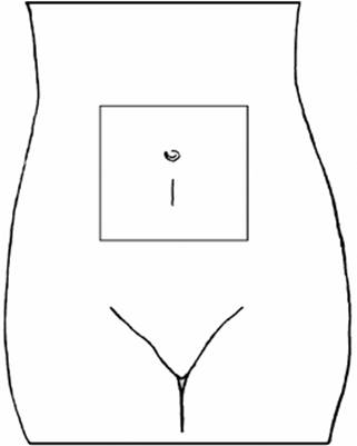
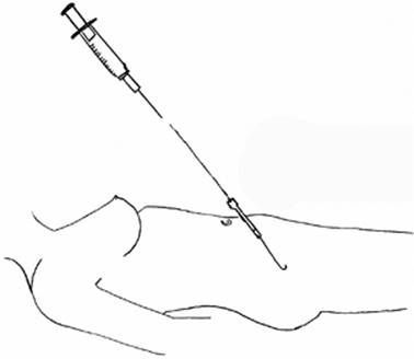
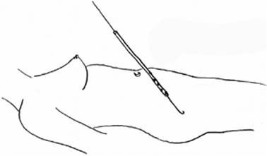
A 0.5-cm skin incision is placed under the umbilicus (or over it in the presence of pregnancy, pelvic hematoma, or a lower midline operative scar). A sheathed needle is introduced with direction toward the pelvis. The needle is connected to a fluid-filled syringe and advanced slowly. When the flow of fluid becomes unobstructed, the needle is in the peritoneal cavity (Fig. 34.6). Needle and syringe are withdrawn, and the plastic sheath is left in place. A guidewire is introduced through the sheath, which is then removed (Fig. 34.7). A dilator is placed over the guidewire and withdrawn. Then, the DPL catheter is introduced and the guidewire is removed (Fig. 34.8). Aspiration is performed first (DPA) and is considered positive if 10 mL of gross blood is aspirated. If the DPA is negative, 1 L of normal saline is infused (DPL). By lowering the normal saline bag below the level of the body, the lavage fluid returns into the bag; the fluid is sent for analysis.
A simpler DPL system includes only a catheter fed over a trocar. The trocar and catheter are introduced in a controlled and slow fashion into the abdomen. Two points of resistance are felt as the trocar passes through the anterior fascia and the peritoneum. As soon as the tip of the trocar passes the second point of resistance—and is presumably into the abdomen—the catheter is fed over it toward the pelvis and the trocar is removed. Experience is needed to perform this technique to prevent trocar injury of abdominal contents.
|
|
|
Figure 34.6. Site for peritoneal lavage catheter placement, just below the umbilicus. |
Open Technique for Peritoneal Catheter Insertion
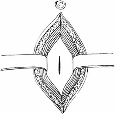
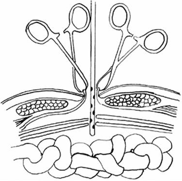
A 2- to 4-cm skin incision is performed under or over the umbilicus. The fascia is visualized and retracted. The fascia is then incised and the peritoneal cavity entered (Fig. 34.9). Under direct observation a DPL catheter is introduced toward the pelvis (Fig. 34.10). Sometimes sutures are placed in the fascia to close the perforation. Although theoretically safer, the open technique does not offer any advantage over the percutaneous technique. It takes longer to perform and may potentially be complicated in obese patients. I recommend the percutaneous technique routinely although the choice of technique is based on operator preference.
|
|
|
Figure 34.7. The needle is removed, and the remaining plastic sheath allows guidewire insertion. |
|
|
|
Figure 34.8. A peritoneal lavage catheter is placed over the guidewire. |
Pitfalls and Complications
The introduction of needles and catheters in the abdominal cavity carries the (very low) risk of injuring the bowel or vessels. The procedure needs to be performed by physicians experienced with the procedure, which is becoming uncommon as the procedure is not frequently performed (14). Once-useful cell counts need to be viewed with caution, as the indications for surgical exploration after abdominal trauma have changed and many injuries are managed nonoperatively. Infusing the lavage fluid but being unable to retrieve it is not uncommon. Slight reposition of the catheter may help.
|
|
|
Figure 34.9. Open technique for peritoneal lavage catheter insertion with direct visualization and incision of the abdominal fascia. |
|
|
|
Figure 34.10. Insertion of the peritoneal lavage catheter under direct vision. |
Cricothyroidotomy
Indications
Cricothyroidotomy is a real emergency and reserved for those patients who cannot be intubated orally or nasally or have lost a preexisting oral airway and are desaturating. It would be a mistake to attempt a tracheostomy in such patients, as this consumes considerably more time. Because the cricothyroid space is superficial in relationship to the skin, it should be selected as the easiest point—even if suboptimal—for insertion of a life-saving airway.
Technique
Open Cricothyroidotomy
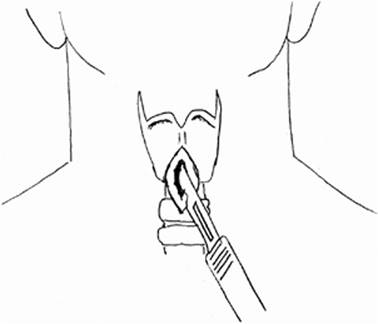
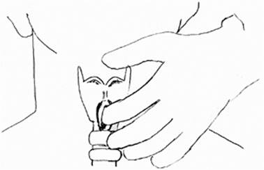
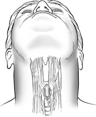
A vertical incision is placed above the cricothyroid space (Fig. 34.11). This incision is preferred over a horizontal or collar-type incision because it can be extended over the trachea and decreases the likelihood of bleeding from injury to the anterior jugular veins, which run close to the midline of the neck. After sharp incision of any soft tissue between the skin and cricoid cartilage, the cricothyroid space is identified by palpation (Fig. 34.12). Any bleeding at this point is ignored, as the sheer goal is to establish an airway as soon as possible. A pointed clamp is introduced through the cricothyroid membrane and opened to dilate the space (Fig. 34.13). Experienced surgeons can use the scalpel to incise the membrane, although the risk exists for injuring the cartilage or posterior wall. The thyroid cartilage is immobilized and pulled upward and anteriorly with a tracheostomy hook. The tracheostomy hook is essential for this procedure. A no. 4 tracheostomy tube is introduced. If the space is wide, a no. 6 tube is preferable. The bleeding is controlled by sutures, electrocoagulation, or pressure.
|
|
|
Figure 34.11. Vertical incision at the cricothyroid space. |
Percutaneous Cricothyroidotomy
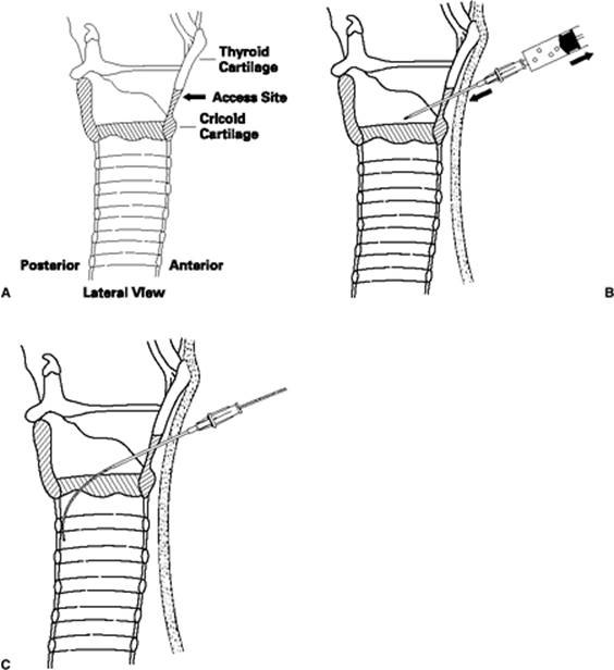
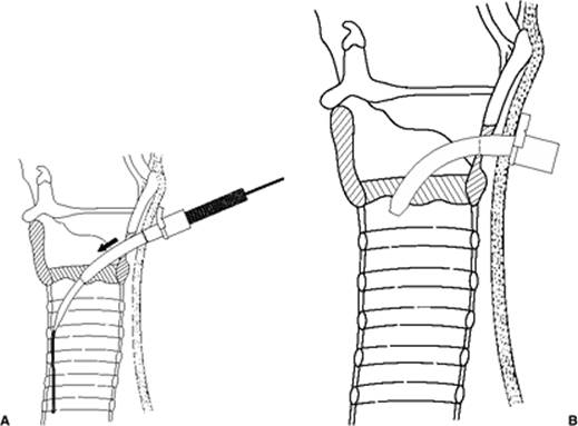
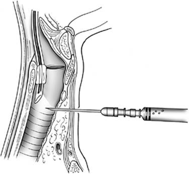
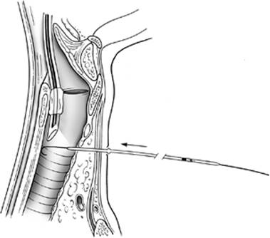
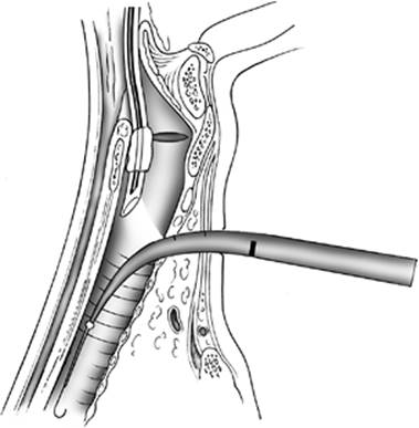
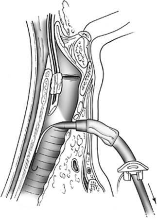
A vertical incision is made. A hollow needle is introduced through the cricothyroid space (Fig. 34.14A, B) and a guidewire is introduced through the needle (Fig. 34.14C), which is then removed. Dilation of the trachea takes place over the guidewire by introducing a dilator (Fig. 34.15A). Finally, a no. 4 tracheostomy tube is placed over a guiding dilator and the guidewire (Fig. 34.15B). The dilator and guidewire are removed, and the tube is left in place and secured to the skin.
|
|
|
Figure 34.12. Digital identification of the cricothyroid space. |
|
|
|
Figure 34.13. Dilatation of the cricothyroid membrane and insertion of the tracheostomy tube. |
Pitfalls and Complications
Despite the apparent simplicity of the technique, a cricothyroidotomy can become a challenging procedure, as the pressure to establish an airway in a dying patient is great. Blood can obscure the field and create additional difficulty. Incorrect identification of the cricothyroid space and placement of the incision above the thyroid cartilage is possible (15). Inadequate opening of the cricothyroid membrane and loss of valuable minutes while trying to insert the tracheostomy tube through a very narrow opening is again not uncommon. Injury of the thyroid and cricoid cartilage, vocal cords, or posterior tracheal wall and esophagus are additional intra-operative complications. The unfortunate combination of a procedure requiring the most experienced person and the lack of time to have such a person present will unavoidably be the cause for complications (16).
There is controversy about the need to convert the cricothyroidotomy to a tracheostomy at a later stage. Previous standard teaching recommended that a tracheostomy should be performed because cricothyroidotomy is associated with a higher degree of tracheal stenosis if left in place for a long time. However, more recent studies have repeatedly refuted this and find no need for incising the trachea twice (17). My personal practice is to leave cricothyroidotomies in place for as long as they are needed to ventilate the patient without converting to a tracheostomy.
Percutaneous Tracheostomy
Indications
A tracheostomy is placed in patients who cannot be safely extubated or have failed extubation. Decrease in airway resistance and improved pleural toilet are major advantages of tracheostomy over orotracheal intubation. An added advantage is the removal of tubes from the patient's mouth, allowing better oral hygiene and the ability to speak with fenestrated tracheostomy tubes. The technique for open tracheostomy will not be described because it is a procedure that should be performed strictly by surgeons and preferably in the operating room. The percutaneous technique is safe, easy to teach, and can be routinely performed at the bedside (18,19).
Technique
Multiple methods of percutaneous tracheostomy have been reported but one, described by Ciaglia, is the most widely used, validated by multiple articles from different groups, and described below. Ideally, the neck is hyperextended by placing a pillow under the patient's shoulders but can be left in the neutral position if spinal precautions are maintained. After preparation of the neck, the site of incision is selected to be in the middle between the cricoid cartilage and sternal notch, which corresponds to the second or third tracheal cartilage. The procedure is performed under bronchoscopic guidance. The bronchoscope is introduced through the orotracheal tube, and the tube is pulled to the level immediately below the vocal cords. A 2- to 3-cm vertical incision is placed, and the subcutaneous tissue and pretracheal muscles are bluntly dissected until the trachea is palpated (Fig. 34.16). A sheathed needle connected to a fluid-filled syringe is introduced. Aspiration of bubbles into the syringe indicates entry into the trachea, also confirmed by the bronchoscope (Fig. 34.17). The needle is pushed in 2 mm farther since the sheath is shorter than the needle. The needle and syringe are removed, and the sheath remains in place. The syringe is placed back on the sheath and air aspirated to confirm that the sheath remains in the airway and has not dislodged during removal of the needle. A J-tipped guidewire is introduced through the sheath into the trachea, and the sheath is then removed (Fig. 34.18). The track is dilated by a short firm dilator, following which a large curved dilator (Fig. 34.19), fed over a guiding tube, is introduced over the guidewire. The large curved dilator has a mark to guide how deep it should be inserted into the airway. Now the trachea is adequately dilated to accommodate the tracheostomy tube. The curved dilator is removed, and the tracheostomy tube (usually a Shiley no. 8) is fed over a 28 Fr dilator, guided by the guidewire/guiding tube complex into the trachea (Fig. 34.20). Although I almost routinely use a no. 8 tracheostomy tube, on the rare occasions that a no. 6 is required, it will be fed over a 26 Fr dilator. The kit contains several sizes of dilators to accommodate different caliber tracheostomy tubes. A single cannula tracheostomy tube will have the same internal diameter as a double cannula tube but a smaller external diameter making it easier for insertion. All these steps are visualized through the bronchoscope although during insertion of the main dilator, the force required to push the dilator may temporarily collapse the trachea for several seconds with poor visualization through the bronchoscope.
|
|
|
Figure 34.14. A: Access site for cricothyroidotomy (lateral view). (From Cook Medical, Inc., with permission.) B: Localization of the cricothyroid space and placement of catheter (lateral view). (From Cook Medical, Inc., with permission.) C: Insertion of guidewire through the hollow catheter (lateral view). (From Cook Medical, Inc., with permission.) |
|
|
|
Figure 34.15. A: Dilatation of the tract (lateral view). (From Cook Medical, Inc., with permission.) B: Placement of the tracheostomy tube in the cricothyroid space (lateral view). (From Cook Medical, Inc., with permission.) |
|
|
|
Figure 34.16. Placement of incision for percutaneous tracheostomy. |
Finally, the guidewire, guiding tube, and curved dilator are removed and the tracheostomy tube is left in place. The bronchoscope is withdrawn from the endotracheal tube (which remains in place) and inserted into the newly placed tracheostomy tube to confirm correct placement by visualizing the carina. The cuff of the tracheostomy tube is inflated, and the tube is connected to the ventilatory circuit. Chest movement, airway pressures, oxygen saturation, and end-tidal carbon dioxide are additional methods to confirm that the tracheostomy is correctly placed and working. It is at this time only that the endotracheal tube is removed. The tracheostomy tube is sutured and taped in place. Of note, if the track created during the percutaneous technique is tight it matures very fast around the tube. Therefore, if the tube needs to be exchanged or downsized, this can be performed safely in 5 days, as opposed to 8 to 10 days usually recommended with the open technique.
|
|
|
Figure 34.17. Insertion of fluid-filled syringe under bronchoscopic guidance and aspiration of bubbles. |
|
|
|
Figure 34.18. Insertion of guidewire and guiding catheter. |
|
|
|
Figure 34.19. Dilation with the large progressive curved dilator. |
|
|
|
Figure 34.20. Insertion of the tracheostomy tube over a guiding dilator. |
Pitfalls and Complications
Loss of airway is the most important concern (20). It can occur by unrecognized pretracheal or paratracheal placement of the dilators, which dilate the soft tissues instead of the trachea, leading to placement of the tracheostomy tube outside of the trachea. Bronchoscopic guidance is key to avoid this, and although I do not consider it necessary for experienced surgeons, I would encourage most physicians to use it. Also, the endotracheal tube should not be removed before the very end of the procedure and after correct placement of the tracheostomy tube is confirmed bronchoscopically and/or by unobstructed introduction of a suction catheter through the tube, normal chest movements, and expected ventilatory parameters. The bronchoscope may be used to suction blood clots, which can cause major airway occlusion, and also to obtain sputum cultures if indicated.
Bleeding is usually not a problem, and I routinely do not use electrocoagulation. On occasion, however, injury to an anterior vessel or the thyroid may cause bleeding through the wound. In most cases, one needs to complete the procedure fast to prevent blood from draining into the airway and achieve hemostasis by compression of the tracheostomy tube against the track. It is very rare that bleeding will persist, and under such circumstances the incision should be enlarged and the wound explored at the bedside or ideally in the operating room. Superficial bleeders may easily be suture ligated.
A common error is not withdrawing the endotracheal tube far enough, leading to impalement of the tube/balloon (or even the bronchoscope) with the finder needle.
Tube dislodgement may be a catastrophic complication, particularly if it occurs early after the operation (21). For this reason, the tube should be secured in place by sutures and a tape. Morbidly obese patients with particularly thick necks may need longer tracheostomy tubes.
Percutaneous Gastrostomy
Indications
A gastrostomy is required for patients who cannot be fed through the mouth because of inability to swallow, prolonged intubation, obstructing lesions of the pharynx or esophagus, or extensive neck operations. Although short-term nutrition can be offered through a nasogastric tube, a gastrostomy is preferred for longer needs.
Technique
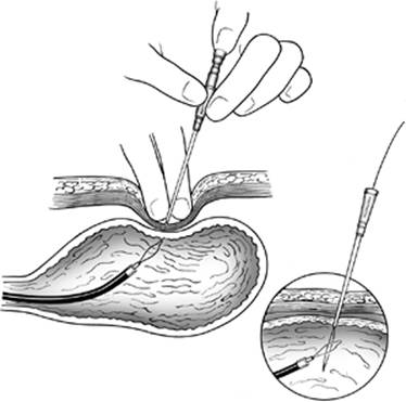
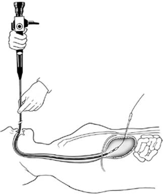
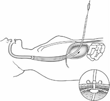
The epigastrium and left upper quadrant are prepared. The procedure starts with an esophagogastroscopy and insufflation of the stomach, so that it apposes the anterior abdominal wall. An appropriate site of placement is selected by applying digital pressure on the skin, which is seen through the gastroscope as an indentation to the stomach. Transillumination should also be possible at the selected site of placement. A long needle covered by a plastic sheath is introduced through the skin and abdominal muscles into the stomach (Fig. 34.21). The needle is withdrawn and the plastic sheath left in place. A snare is introduced through the appropriate port of the gastroscope. A guidewire is placed in the stomach through the plastic sheath and grasped by the snare (Fig. 34.22). The gastroscope, snare, and guidewire are withdrawn out of the mouth. The guidewire is disengaged from the snare and tied to the tip of a percutaneous gastrostomy tube. A 2-cm incision is made on the skin, and the guidewire is pulled. In this way, the gastrostomy tube is also pulled back into the mouth and, through the esophagus and stomach, out of the skin (Fig. 34.23). The gastroscope is reintroduced into the stomach and confirms correct placement of the tube. The tube is secured by placing a flange and suturing it to the skin. It can be used within 6 hours for medication and 12 hours for feeds.
|
|
|
Figure 34.21. Insertion of needle into the stomach under endoscopic guidance. |
|
|
|
Figure 34.22. Guidewire snared and pulled with gastroscope through mouth. |
Pitfalls and Complications
It is necessary to confirm that there are no vessels and no intervening hollow viscera (such as the colon) between the stomach and anterior abdominal wall. The indentation created by digital pressure should be clearly evident by the gastroscope, and transillumination at that site should be possible (22). In this way, bleeding or inadvertent injuries are avoided.
|
|
|
Figure 34.23. Gastrostomy tube pulled through stomach. |
Infection of the wound should be recognized early and can be avoided with strict sterile technique. Usually, the tube does not need to be removed. The infection is treated by opening the wound and administering antibiotics. There is a suggestion that the initial tract should not be “tight” and that a larger skin wound from the beginning prevents infection (23). I do not agree and always create a small wound that is only large enough to accommodate the tube.
Tube dislodgement may occur either if the stomach is under tension (e.g., on a patient with hiatal hernia or with adhesions) or because the tube was not secured adequately and was inadvertently pulled (24). Both complications are usually preventable and should be avoided by recognizing that the anatomy is not favorable for a gastrostomy or suturing the gastrostomy tube adequately to the skin.
Abdominal pressure monitoring
Indications
Patients at risk of or developing abdominal compartment syndrome should have the intra-abdominal pressures measured routinely. Abdominal hypertension, the elevation of pressure in the abdominal cavity due to bleeding or visceral swelling, leads to compromise of cardiac output, tissue perfusion, and ventilation, all eventually resulting in death if untreated (25). Clinical diagnosis is important, as the experienced physician will recognize a tense abdomen in the presence of hypotension, oliguria, and high airway pressures. Multiple methods have been described to monitor the intra-abdominal pressure. The most widely accepted method is the measurement of bladder pressure because of the logical assumption that the intraperitoneal pressure is transmitted on the bladder wall. Pressures below 10 cm H2O are considered normal, 10 to 15 acceptable for postoperative patients, 15 to 20 worrisome and possibly in need of action, and over 20 as cause for decompression in most cases (26). This technique is described below.
Technique
Presumably the bladder is empty because such patients always have a Foley catheter. With the patient lying flat and under aseptic technique, a three-way stopcock is connected to a syringe and pressure monitor. Fifty to 100 mL of saline are injected into the bladder, and the stopcock is opened toward the pressure monitor. It is important to level the monitor in advance, so that the 0 mark corresponds to the level of the pubic symphysis (see Fig. 73.3 in Secondary and Tertiary Triage of the Trauma Patient). There is currently in the market a system that allows continuous measurement of pressures without interrupting the continuity of the Foley circuit and therefore decreasing the risk of urinary infection.
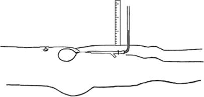
An easy and simple technique that does not require any instruments is the U-tube technique. According to it, the Foley is elevated while allowing a U-loop to form. If there is not enough urine in the tube, saline needs to be injected. The column of urine or injected fluid that forms is measured between the pubic symphysis and meniscus (Fig. 34.24). This measurement represents the abdominal pressure.
|
|
|
Figure 34.24. Measurement of intra-abdominal pressure using column of urine/water in the Foley catheter tubing. |
Pitfalls and Complications
The most dangerous pitfall is the exclusive reliance on bladder pressure measurements. Clinical examination should always be the principal reason for continued observation or immediate decompression. Bladder pressure measurements should only support the clinical diagnosis.
Pericardiocentesis
Indication
The pericardial space can accommodate large volumes of fluid if accumulation occurs over a long period of time, whereas cardiac tamponade develops with even small quantities of fluid; it thus happens abruptly. Pericardiocentesis is indicated to treat tamponade or diagnose the nature of chronic fluid (27). The latter is performed under ultrasonographic guidance. The former will be described below, although pericardiocentesis for traumatic tamponade is rarely useful. Unless the patient is in a remote area with difficult access to a trauma center, pericardiocentesis is not indicated; rapid sternotomy and control of the bleeding is.
Technique
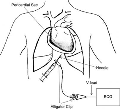
With the patient supine, a standard pericardiocentesis kit or, in true emergencies, a central line kit can be used. A hollow needle is inserted approximately 1 cm below the costal margin and slightly to the left of the midline. The direction is toward the left shoulder. The needle is advanced slowly under the rib (Fig. 34.25). Electrocardiographic monitoring is possible by attaching an alligator clip to the needle. ST-segment elevations indicate contact of the needle with the epicardium. Aspiration of fluid or blood obviously indicates that the needle is in the pericardial sac. Aspiration of blood relieves the pericardial tamponade, and a guidewire is inserted through the needle. Using a Seldinger technique, a catheter is inserted and used to withdraw further fluid or blood over time, if needed. With wide availability of portable ultrasound machines, emergent tapping of pericardial space may be safer than the previously used “blind” technique as described above.
|
|
|
Figure 34.25. Technique of pericardiocentesis. |
Pitfalls and Complications
Pericardiocentesis is a potentially dangerous technique, if performed blindly (28). When done by radiologic guidance for stable conditions, little risk if involved. When performed under emergency situations for presumed cardiac tamponade, there is risk of injuring the heart, particularly if the clinical diagnosis of tamponade is not correct and the space between the pericardium and epicardium is very narrow. Additionally, misplacement of the needle—most typically under the heart—is not unusual. As mentioned previously, blind pericardiocentesis for traumatic injury purposes has been nearly abandoned in urban hospital settings.
Percutaneous Inferior Vena Cava Filter Placement
Indications
Inferior vena cava filter (VCF) use has met an explosive growth for the treatment and prophylaxis of pulmonary embolism (29). The evidence about its effectiveness is contradictory, another interesting medical example of how standard of care is formed in the absence of solid evidence. Absolute indications for filter placement are as follows: recurrent pulmonary embolism despite anticoagulation, contraindications to anticoagulation in the presence of pulmonary embolism or proximal deep venous thrombosis, and complications of anticoagulation prompting its cessation. Relative indications include polytrauma patients at high risk for venous thromboembolism, critically ill patients with tenuous respiratory status in whom even a small pulmonary embolism may prove detrimental, and large free-floating venous clot.
Multiple types of permanent filters exist, although lately removable filters are used with increasing frequency and in many institutions predominantly or exclusively (30). The Gunther Tulip (COOK, Bloomington, IN) retrievable VCF consists of four main struts, each bearing a hook at the inferior end. On the superior joint of the four struts is attached a small hook, which is used for retrieval. It is inserted through a sheath with an outer diameter of 8.5 Fr. The Recovery (Bard, Tempe, AZ) RVCF is based on a bilevel design with six stabilizing arms and six anchoring legs and is introduced through a 9 Fr sheath. The G2 (COOK, Bloomington, IN) RVCF is a recently developed system consisting of twelve nitinol wires forming a two-level structure with six legs and six arms similarly to the Recovery system. All of the above devices are MRI compatible. Two techniques are dominant in performing filter insertion at the bedside and will be described below: the fluoroscopic-guided and the endovascular ultrasound-guided techniques.
Technique
Fluoroscopy Guided
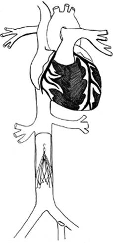
After a screening duplex ultrasound is performed to examine for femoral venous clots, portable fluoroscopy is used to define the L2-4 lumbar region. The site of venous access is selected—typically the left or right femoral vein—and venous cannulation is performed using a Seldinger technique. A 4 or 5 Fr angiographic catheter is advanced over a guidewire into the inferior vena cava and up to the second lumbar vertebra. Contrast material is injected, and the cava is imaged to delineate its anatomy and size. In particular, the renal veins are defined as the landmark below which the filter should be placed. After venography is completed, the pigtail catheter is exchanged for the sheath, which is inserted over a dilator. The sheath is positioned under the renal veins, and the filter carrier system is advanced into the sheath. The filter is then deployed, completion venography is performed, and the sheath is withdrawn. The filter sits caudad to the renal veins (Fig. 34.26).
Intravascular Ultrasonographic (IVUS) Guided (31)
Insertion is usually performed through a right femoral vein approach. A micropuncture is made in the vein using a 4 Fr catheter, and a 0.035 wire is introduced. An 8 Fr sheath is inserted into the inferior vena cava, and the IVUS (In-Vision Gold, Volcano Corp, Rancho Cordova, CA) is advanced over the wire through the iliac venous system up to the level of the right atrium. Then, it is slowly withdrawn to evaluate the inferior vena cava in a retrograde fashion. The right renal artery and bilateral veins are visualized, and the maximum diameter of the vena cava is measured. After a second puncture in the right common femoral vein, the delivery sheath for a VCF is introduced over a 0.035 guidewire. The sheath and then the VCF are advanced to the level of the renal veins. Deployment is performed under direct IVUS visualization. Confirmation of correct placement below the renal and above the iliac veins is established ultrasonographically. The catheters and sheaths are removed and direct pressure held over the femoral puncture sites. A postinsertion plain radiograph is routinely performed to verify correct placement at the L2-4 level. This technique is valuable in patients at risk for renal failure due to avoidance of radiocontrast dye.
|
|
|
Figure 34.26. Position of vena cavae filters, caudad to the renal veins. |
Pitfalls and Complications
The potential for complications starts with the venous access. Access complications (the same as any central venous access) include bleeding, hematoma, arteriovenous fistula, hemopneumothorax, and cardiac dysrhythmias. Misplacement outside the IVC or at an incorrect location is a common complication of insertion and has been reported to be as high as 4.6% (32). Locations for filter misplacement include renal veins, gonadal veins, or unintended suprarenal placement. Insertion site venous thrombosis and vena cava occlusion are potential complications of filters. Access via the internal jugular or subclavian vein results in a lower incidence of thrombosis when compared to femoral access. Caval thrombosis rates do not appear to vary significantly among the available filters. Some reports show very high rates of caval thrombosis (up to 25%) while others for the same filter are much lower (33). Two explanations for this disparity are: different patient populations (i.e., trauma versus malignancy) and provider related. It is expected that with the increasing use of retrievable VCFs, the rate of caval thrombosis will decrease. Pulmonary embolism in the presence of an IVC filter has been reported in 3% to 7% of patients after filter placement in series >50 patients (34). Guidewire entrapment occurs during placement of central venous and pulmonary artery catheters as well as during catheter exchanges. Attempts at removal of an entrapped item can lead to filter displacement and vessel damage when excessive force is applied. Straight guidewires should be used for all new central venous catheters in patients with indwelling IVC filters.
References
1. Gillman L, Leslie G, Williams T, et al. Adverse events experienced while transferring the critically ill patient from the emergency department to the intensive care unit. Emerg Med J. 2006;23:858–861.
2. Venkataraman ST, Orr RA. Intrahospital transport of critically ill patients. Crit Care Clin N Am. 1992;8:525–531.
3. Warren J, Fromm RE Jr, Orr RA, et al. American College of Critical Care Medicine. Guidelines for the inter- and intrahospital transport of critically ill patients. Crit Care Med. 2004;32:256–262.
4. Barba C. The intensive care unit as an operating room. Surg Clin N Am. 2000;80:957–973.
5. Van Natta TL, Morris JA, Eddy VA, et al. Elective bedside surgery in critically injured patients is safe and cost-effective. Ann Surg. 1998;227:618–624.
6. Dalbec DL, Krome RL. Thoracostomy. Em Med Clin N Am. 1986;4:441–457.
7. Advanced Trauma Life Support Manual: Thoracic Trauma. Chicago, IL: American College of Surgeons; 1993.
8. Demetriades D. Tube thoracotomy. In: Shoemaker WC, Demetriades D, Velmahos G, eds. Procedures and Monitoring for the Critically Ill. Philadelphia, PA: WB Saunders; 2002:47–53.
9. Demetriades D, Breekon V, Breckon C, et al. Antibiotic prophylaxis in penetrating injuries of the chest. Ann R Coll Surg Engl. 1991;73:348–351.
10. Vassiliu P, Velmahos GC, Toutouzas KG. Timing, safety, and efficacy of thoracoscopic evacuation of undrained post-traumatic hemothorax. Am Surg. 2001;67:1165–1169.
11. Kimbrell JB, Yamzon J, Petorne P, et al. Intrapleural thrombolysis for the management of undrained traumatic hemothorax: a prospective observational study. J Trauma. 2007;62:1175–1180.
12. Root HD, Hauser CW, McKinley CR, et al. Diagnostic peritoneal lavage. Surgery. 1965;5:633–636.
13. Kuncir E, Velmahos GC. Diagnostic peritoneal aspiration: the foster child of DPL. Intern J Surg. 2007;5:167–171.
14. Velmahos GC, Demetriades D, Stewart M, et al. Open versus closed diagnostic peritoneal lavage: a comparison on safety, rapidity, efficacy. J R Coll Surg Edinb. 1998;43:235–238.
15. Goumas P, Kokkinis K, Petrocheilos J, et al. Cricothyroidotomy and the anatomy of the cricothyroid space. An autopsy study. J Laryngol Otol. 1997;111:354–356.
16. Cornwell EE, III. Cricothyroidotomy. In: Shoemaker WC, Demetriades D, Velmahos GV, eds. Procedures and Monitoring for the Critically Ill. Philadelphia, PA: WB Saunders, 2002:43–45.
17. Wright MJ, Greenberg DE, Hunt JP, et al. Surgical cricothyroidotomy in trauma patients. South Med J. 2003;96:465–467.
18. Friedman Y, Fildes J, Mizock B, et al. Comparison of percutaneous and surgical tracheostomies. Chest. 1996;110:480–485.
19. Velmahos GC, Gomez H, Boicey CM, et al. Bedside percutaneous tracheostomy is safe and easy to teach: prospective evaluation of a modification of the current techniques on 100 patients. World J Sur. 2000;24:1109–1115.
20. Dulguerov P, Gysin C, Perneger TV, et al. Percutaneous or surgical tracheostomy: a meta-analysis. Crit Care Med. 1999;27:1617–1625.
21. Velmahos GC, Demetriades D. Common bedside procedures in the intensive care unit. In: Shoemaker WC, Ayres SM, Grenvik A, et al., eds. Textbook of Critical Care. 4th ed. Philadelphia, PA: WB Saunders; 2000:114–119.
22. Miller RE, Castlemain B, Lacqua FJ, et al. Percutaneous endoscopic gastrostomy. Results in 316 patients and review of literature. Surg Endosc. 1989;3:186–190.
23. Sharma VK, Howden CW. Meta-analysis of randomized, controlled trials of antibiotic prophylaxis before percutaneous endoscopic gastrostomy. Am J Gastroenterol. 2001;96:1951–1952.
24. Shallman RW, Norfleet RG, Hardache JM. Percutaneous endoscopic gastrostomy feeding tube migration and impaction in the abdominal wall. Gastrointest Endosc. 1988;34:367–368.
25. Diebel LN, Wilson RF, Dulchavsky SA, et al. Effect of increased intra-abdominal pressure on hepatic, arterial, portal, venous microcirculatory blood flow. J Trauma. 1992;33:279–283.
26. World Society of the Abdominal Compartment Syndrome. www.wsacs.org.
27. Allen KB, Faber LP, Warren WH, et al. Pericardial effusion: subxiphoid pericardiostomy versus percutaneous catheter drainage. Ann Thor Surg. 1999;67:437–440.
28. Focht G, Becker RC. Pericardiocentesis. In: Rippe JM, Irwin RS, Fink MP, et al., eds. Procedures and Techniques in Intensive Care Medicine. Boston, MA: Little & Brown; 1995:111–116.
29. Sing RF, Smith CH, Miles WS, et al. Preliminary results of bedside inferior vena cava filter placement: safe and cost-effective. Chest. 1998;114:315–316.
30. Karmy-Jones R, Jurkovich G, Velmahos GC, et al. Practice patterns and outcomes after retrievable vena cava filters in trauma patients: an AAST multicenter study. J Trauma. 2007;62:17–25.
31. Garrett JV, Passman MA, Guzman RJ, et al. Expanding options for bedside placement of inferior vena cava filters with intravascular ultrasound when transabdominal duplex ultrasound imaging is inadequate. Ann Vasc Surg. 2004;18:329–334.
32. Kazmers A, Ramnauth S, Williams M. Intraoperative insertion of Greenfield filters: lessons learned in a personal series of 152 cases. Am Surg. 2002;68(10):877–882.
33. AbuRahma AF, Robinson PA, Boland JP, et al. Therapeutic and prophylactic vena caval interruption for pulmonary embolism: caval and venous insertion site patency. Ann Vasc Surg. 1993;7:561–568.
34. Geisinger MA, Zelch MG, Risius B. Recurrent pulmonary embolism after Greenfield filter placement. Radiology. 1987;165:383–384.