INTRODUCTION
There is increasing awareness of acute and chronic aortic disorders and the pivotal role of echocardiography in diagnosis and monitoring prognosis. There is a variety of congenital and heritable disorders that affect aorta. Acute aortic disorders presenting in emergency include aortic dissection, intramural hematoma and aortic ulcer, and rarely traumatic aortic transection. Longitudinal progression of chronic aortic diseases and appropriate timing of open or endovascular surgery are usually derived from serial noninvasive imaging studies including echocardiography. Echocardiography, especially transesophageal one, is an ideal imaging modality for detecting precisely, safely and rapidly suspected acute or chronic pathology of ascending aorta with quantitative information on aneurysm formation and progression, as well as on tear location, extent and type of dissection including evaluation for imminent complications. Ultrasound techniques for imaging of the aorta include transthoracic echocardiography (TTE), transesophageal echocardiography (TEE), abdominal ultrasound and intravascular ultrasound. However, echocardiography has limited role in detecting aortic pathology at sites other than ascending aorta.
STRUCTURE OF AORTA
The aorta is the main trunk of vessels, which conveys the oxygenated blood to the body. It commences at the upper part of the left ventricle, where it is about 3 cm in

Fig. 17.1: Graphical description of anatomy of aorta.
diameter, and after ascending for a short distance, arches backward and to the left side, over the root of the left lung; it then descends within the thorax on the left side of the vertebral column, passes into the abdominal cavity through the aortic hiatus in the diaphragm and ends, considerably diminished in size (approximately 1.75 cm in diameter), opposite the lower border of the fourth lumbar vertebra, by dividing into the right and left common iliac arteries (Fig. 17.1).
PARTS OF AORTA
• Aortic root: The root is the beginning of the aorta. Starting from the aortic valve (annulus) and becoming

Fig. 17.2: Graphic view of aortic root, sinotubular junction and ascending aorta.
(LVOT: Left ventricular outflow tract; RPA: Right pulmonary artery).
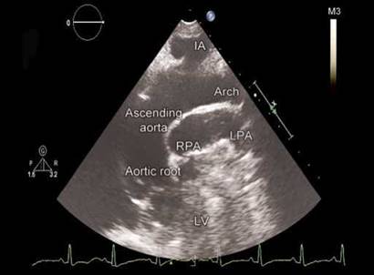
Fig. 17.3: Suprasternal long-axis view showing aortic root, ascending aorta and its arch.
(IA: Innominate artery; LPA: Left pulmonary artery; RPA: Right pulmonary artery; LV: Left ventricle).

Fig. 17.4: Tilted parasternal long-axis view showing aortic root and ascending aorta with posterior relationship.
slightly wider in diameter (sinuses of Valsalva), it gives rise to two coronary arteries and ends at the beginning of the ascending aorta (sinotubular junction) (Fig. 17.2).
• Ascending aorta: This segment of 5 cm length extends upward from the aortic root to the point where the innominate artery branches off the aorta, and the aorta begins to form an arch (Fig. 17.3). It is within the pericardium and no arteries branch from it. There is little support from surrounding tissue and it must face the entire cardiac output volume, making the ascending segment the most vulnerable part of the aorta.
The ascending aorta is covered at its origin by the pulmonary trunk and the right atrial appendage and, higher up, is separated from the sternum by the pericardium, the right pleura, the anterior margin of the right lung, some loose areolar tissue and the remains of the thymus; posteriorly, it rests upon the left atrium and right pulmonary artery (Fig. 17.4). On the right side, it is in relation with the superior vena cava and right atrium, the former lying partly behind it; on the left side, with the pulmonary artery.
• Aortic arch: The arch represents the curved portion at the top of the aorta. The innominate, left common carotid and left subclavian arteries, which supply blood to the head and upper body, branch from the arch. It is outside the pericardial sac and generally has better support from surrounding structures (Fig. 17.5). The aortic arch is divided into proximal (immediately distal to the innominate artery) and distal (immediately distal to the left common carotid artery) segments.
• Descending aorta: This section begins just beyond the origin of left subclavian artery at a relatively narrower portion called isthmus. The descending aorta ends at the diaphragm. It contains the intercostal arteries that feed the spinal cord. The beginning portion of the descending aorta is vulnerable to intimal tear during deceleration conditions (Fig. 17.6).
• Thoracoabdominal aorta: This section begins at the diaphragm and ends at the visceral vessels (celiac, superior mesenteric and renal arteries) (Figs 17.7 and 17.8).

Fig. 17.5: Suprasternal long-axis view showing end of the arch at origin of the left subclavian artery and beginning of the descending thoracic aorta.

Fig. 17.6: Descending thoracic aorta begins just beyond the origin of the left subclavian artery. The segment between the arch and the descending thoracic aorta is called isthmus.

Fig. 17.7: Thoracoabdominal aorta in subcostal long-axis view.

Fig. 17.8: Thoracoabdominal aorta viewed in subcostal long-axis view showing celiac axis and superior mesenteric artery (SMA).
• Abdominal aorta: the abdominal aorta begins below the renal arteries. The aorta ends where it divides into the two iliac arteries. It contains a small artery named the inferior mesenteric artery.
Aorta and its proximal branches act as an elastic buffering chamber beyond the left ventricle (the Windkessel function) and store about 50% of the left ventricular stroke volume during systole. In diastole, the elastic forces of the aortic wall forward this 50% of the volume to the peripheral circulation, thus creating a nearly continuous peripheral blood flow (Fig. 17.9).
ttis systolic-diastolic interplay represents the Windkessel function, which results in reduction of left ventricular afterload and better coronary blood flow and left ventricular relaxation.1
the elastic resistance (or stiffness), which the aorta sets against its systolic distention, increases with aging, with an increase in blood pressure, and with pathological changes such as atherosclerosis.
ttis increased stiffness leads to an increase in systolic blood pressure and a decrease in diastolic blood pressure at any given mean pressure, an increase in systolic blood velocity, an increase in left ventricular afterload and a decrease in subendocardial blood supply during diastole.

Fig. 17.9: Windkessel phenomenon in proximal aorta shown graphically.

Fig. 17.10: Study of aortic circumferential strain by velocity vector imaging.

Fig. 17.11: Normal measurements of aorta.
The elastic properties of the aortic Windkessel can be assessed in vivo in humans in several ways including tissue velocity imaging and deformation imaging. With reduced elasticity, positive circumferential strain tends to decrease (Fig. 17.10).
NORMAL AORTIC MEASUREMENTS AND IMAGING VIEWS
Using different windows, the proximal ascending aorta is visualized in the left and right parasternal long-axis views (Fig. 17.4) and, to a lesser extent, in basal short-axis views. The long-axis view affords the best opportunity for measuring aortic root diameters by taking advantage of the superior axial image resolution. In all patients with
suspected aortic disease, the right parasternal view is recommended for estimating the true size of the ascending aorta.
The ascending aorta is also visualized in the apical long- axis and modified apical five-chamber views; however, in these views, the aortic walls are seen with suboptimal lateral resolution.
Measurements of aortic diameter by echocardiography are accurate when care is taken to obtain a true perpendicular dimension and gain settings are appropriate. Standard measurement conventions established the leading edge-to-leading edge diameter in end diastole and the normative data published in the literature were obtained using the leading edge technique. Some favor inner edge-to-inner edge diameter measurements to increase reproducibility and match those obtained by other methods of imaging the aorta. However, recent improvements in echocardiographic image quality and resolution minimize the differences between these measurement methods.
Normal measurements of various aortic segments are shown in Figure 17.11.
In a normal ascending aorta, the diameter at sinus level is the largest, followed by the sinotubular junction and the aortic annulus.2-4
Suprasternal view depicts the aortic arch and the three major supra-aortic vessels (innominate, left carotid and left subclavian arteries), with variable lengths of the descending and, to a lesser degree, ascending aorta (Fig. 17.6).

Fig. 17.12: Visualization of mid portion of descending thoracic aorta in parasternal long-axis view.
(LV: Left ventricle; LA: Left atrial)

Fig. 17.13: Simultaneous long axis and short axis of the aortic root obtained by three-dimensional transesophageal echocardiography. (LV: Left ventricle)
The entire thoracic descending aorta is not well visualized by transthoracic windows. A short-axis view of the descending aorta can be imaged posteriorly to the left atrium in the parasternal long-axis view. From the apical window, a short-axis cross-section of the descending aorta is seen lateral to the left atrium in the four-chamber view and a long-axis stretch in the two-chamber view. By 90° transducer rotation, a long-axis view is obtained and a mid part of the descending thoracic aorta may be visualized (Fig. 17.12).
Transesophageal echocardiography is an ideal modality to image ascending aorta, part of the arch and descending thoracic aorta. The most important transesophageal views of the ascending aorta, aortic root and aortic valve are the high transesophageal long-axis (at 120°-150°) and short-axis (at 30°-60°) views (Fig. 17.13). A short segment of the distal ascending aorta, just before the innominate artery, remains unvisualized owing to interposition of the right bronchus and trachea.
Like the ascending aorta, the descending aorta often produces an artifactual pseudoaorta located posteriorly to the true aorta ('double-barrel aorta') in TEE views.4
ETIOPATHOGENESIS OF AORTIC DISORDERS
Although most aortic disease is associated with atherosclerosis and hypertension (i.e. aneurysms and dissection), the spectrum of aortic disease is vast and includes various congenital and acquired entities.
The congenital group includes patent ductus arteriosus, aortic hypoplasia, aortic coarctation, interrupted aortic arch, aortopulmonary (AP) window, common arterial trunk, supravalvular aortic stenosis (SAS), aneurysms of sinus of Valsalva and vascular rings.
The acquired disorders include aortic dissection due to extension of a coronary artery dissection, Marfan syndrome, large-vessel vasculitis such as Takayasu arteritis, mycotic aneurysms, aneurysms of sinus of Valsalva, and so on.
Specific conditions associated with therapeutic manoeuvre, such as recoarctation, stent-graft rupture and endoleaks are also evaluated by echocardiography.
Unicuspid and Bicuspid Aortic Valve and Associated Aortopathy
The bicuspid aortic valve is the most common congenital abnormality of the human heart, affecting approximately 1% to 2% of the general population.
Unicuspid and bicuspid aortic valve are an inherited anomaly and commonly associated with proximal aortic dilatation.5,6 Unicuspid or bicuspid aortic valve is associated with abnormal flow patterns and asymmetrically increased wall stress in the proximal aorta (Figs 17.14 to 17.16).
In persons with bicuspid aortic valve (and also the unicuspid aortic valve), the dimensions of the proximal aorta (especially the tubular ascending aorta) are significantly larger than those in persons with tricuspid

Fig. 17.14: Bicuspid aortic valve with proximal aortic dilatation in parasternal long-axis view.


Figs 17.15A to C: Unicuspid aortic valve (A: TEE image and B: threedimensional echo in short axis) with aortic dilatation in TEE long-axis view.
(TEE: Transesophageal echocardiographic).

Fig. 17.16: Dilatation of the ascending aorta with normal aortic root in an 18-year-old boy with unicuspid aortic valve.

Fig. 17.17: Suprasternal long-axis view showing tubular narrowing of the descending thoracic aorta.

Fig. 17.18: Graphical representation of aortic coarctation (left panel) contrasted with actual echocardiographic picture.
aortic valve, even in the absence of significant valvular hemodynamic disturbance. This has been empirically linked to an increased risk of acute aortic complications like aneurysm formation, dissection and rupture. Larger dimensions of the ascending aorta at the time of aortic valve surgery (i.e. > 45 mm) might be associated with the increased rate of late aortic events.
aortic coarctation
Aortic coarctation involves aortic narrowing in the region of the ligamentum arteriosum just distal to the left subclavian artery (Figs 17.17 and 17.18).
Aortic coarctation represents 7% of congenital heart disease. It has a male predominance. The stenotic segment frequently develops in a juxtaductal location but may show
extension into the aortic arch and isthmus. The previous classification into preductal (infantile) and postductal (adult) is less commonly used because aortic coarctation is always periductal.
Aortic coarctation occurs as a solitary lesion in 82% of cases but has multiple associations, including Turner syndrome, bicuspid aortic valve (seen in 22-42% of cases), intracranial aneurysms (10% of cases), ventricular and atrial septal defects and Shone complex (i.e. left ventricular outflow tract obstruction and parachute mitral valve). Aortic coarctation may also be associated with aortic hypoplasia—isolated isthmic hypoplasia, isolated aortic arch hypoplasia or isthmic and aortic arch hypoplasia.7,8
A significant coarctation is when the ratio of diameter of the coarct segment to aortic diameter at diaphragm is < 0.5. Examination by continuous wave Doppler echocardiography is an effective noninvasive method of assessing the severity of coarctation of the aorta, particularly when systolic and diastolic events are considered together (Fig. 17.19). Peak systolic gradient of > 40 mm Hg and diastolic pressure half time of > 100 milliseconds are highly specific for severe coarctation. Diastolic parameters are much more useful in assessing severity. Recoarctation is defined by the presence of peak systolic gradient > 10 mm Hg.
Interrupted aortic arch is defined as a complete luminal and anatomical discontinuity between the ascending and descending aorta (Fig. 17.20). It is rare, accounting for only 1% of congenital heart diseases. It is of three types.8
• Type A: It is defined as an interruption distal to the left
subclavian artery.

Fig. 17.19: Continuous wave Doppler interrogation of coarct segment (left panel). Graphical description (right panel) shows systolodiastolic gradients.

Fig. 17.20: Type A aortic interruption (arrow) with hypoplastic pulmonary artery (PA) shown in suprasternal long-axis view.

Figs 17.21A and B: Type A aortic interruption with low-velocity continuous flow in thoracoabdominal aorta through aortopulmonary collaterals.
• Type B: the absent segment is between the left common carotid artery and left subclavian artery.
• Type C: It is defined as an interruption distal to the innominate artery. Descending thoracic aorta reconstitutes from the pulmonary artery collaterals (Fig. 17.21).
aneurysm of sinus of valsalva
the Valsalva sinuses are three subtle dilatations of the aortic root wall that arise between the aortic valve annulus and the sinotubular ridge (Fig. 17.22).
Each sinus is associated with a corresponding right, left or noncoronary aortic valve cusp.
Aneurysm of aortic sinuses, also known as aneurysm of sinus of Valsalva, is a rare congenital disorder.
Congenital aneurysm of sinus is caused by a dilatation, usually of one sinus of Valsalva, due to a separation between the aortic media and the annulus fibrosus (Figs 17.23 to 17.26).
Right sinus is commonly involved (85%) and the left sinus is least involved (< 5%).
Aneurysm of sinus of Valsalva may rupture into cardiac chambers to establish aortocameral fistulae. The right sinus usually ruptures in or communicates with the right ventricular outflow tract, noncoronary sinus aneurysm in right atrium and the left sinus of Valsalva may rupture into the left ventricle, left atrium, pulmonary artery or in the pericardium.9,10
the abnormality is usually congenital but may be associated with Marfan Syndrome, Ehlers-Danlos

Fig. 17.22: Three-dimensional short-axis view showing all three sinuses of Valsalva.

Fig. 17.23: Aneurysm of right sinus of Valsalva shown in short-axis view (arrow).

Fig. 17.24: Transthoracic parasternal long-axis view showing aneurysm of right sinus of Valsalva (arrow).
Syndrome, cystic medial necrosis, trauma, infective endocarditis, tuberculosis, syphilis and also atherosclerosis.
Aneurysms of the sinus of Valsalva are usually diagnosed after an acute rupture into an adjacent cardiac structure (Figs 17.25 to 17.27). Prior to rupture, aneurysms of the sinus of Valsalva may present with conduction- system abnormalities attributable to erosion into the interventricular septum, thromboembolism originating in the aneurysm sac, myocardial ischemia attributable to coronary compression and aortic regurgitation (Fig. 17.28).
Functional aortic regurgitation is related to the aortic annulus/root mismatch. Aortic root dilatation, whether symmetrical or asymmetrical, causes leaflet tethering.
Gerbode's shunt, wherein the aneurysm communicates with the right atrium, is the second commonest anomaly (Figs 17.29 and 17.30).
• Nonruptured aneurysms may be asymptomatic and incidentally discovered, or they may be symptomatic and manifest acutely with mass effect on adjacent cardiac structures.
• Ruptured Valsalva sinus aneurysms result in an aortocardiac shunt and may manifest as insidiously progressive congestive heart failure, severe acute chest pain with dyspnea or, in extreme cases, cardiac arrest.
• Cardiac tamponade may occur if the rupture involves the pericardial space.
• Aortic sinus aneurysm is more prevalent in Asian countries and correlates with more supracristal ventricular septal defects (VSDs; ~ 60%).
• Associated structural defects in congenital aortic sinus aneurysms included supracristal or perimembranous VSD (30-60%), bicuspid aortic valve (15-20%) and aortic regurgitation (44-50%). Approximately 10% of patients with Marfan syndrome have some form of sinus dilatation (Fig. 17.31).
Two-dimensional (2D) Doppler echocardiography easily makes this diagnosis, but real-time threedimensional (3D) echocardiography allows for complete visualization of the aneurysm neck and its relation to the surrounding structures, including the aortic valve (Figs 17.32 and 17.33).
The criteria for diagnosing a Valsalva sinus aneurysm include:
• Origin above the aortic annulus.
• Saccular shape.

Figs 17.25A and B: Three-dimensional echocardiographic short-axis images showing windsock effect of aneurysm of right sinus of Valsalva (arrows).

Figs 17.26A and B: Color flow Doppler interrogation showing communication between the aneurysm of the right sinus with right ventricular outflow tract (upper panel) in modified long-axis view. Continuous wave Doppler spectrum with continuous flow at high velocities is shown in lower panel.

Fig. 17.27: Ruptured aneurysm of right sinus of Valsalva into the right ventricular outflow tract (arrow) with prominent diastolic flow accentuation due to venturi effect (right panel) in the spectrum of systolodiastolic flow.

Fig. 17.28: Unruptured aneurysm of the right sinus of Valsalva (arrow) with flail aortic leaflets due to loss of support to the aortic annulus.

Fig. 17.29: Transesophageal echocardiographic view at 80° showing aneurysm of noncoronary sinus of Valsalva protruding into the right atrium (arrows).

Figs 17.30A and B: (A) Ruptured aneurysm of noncoronary sinus communicating with the right atrium just below the posterior tricuspid valve leaflet. Figure B shows the color flow jet extending toward the tricuspid valve.

Fig. 17.31: Transthoracic short-axis view showing dilatation of all three sinuses in a patient with Marfan syndrome.

Fig. 17.32: Three-dimensional echocardiographic view of aneurysm of right aortic sinus (arrow).
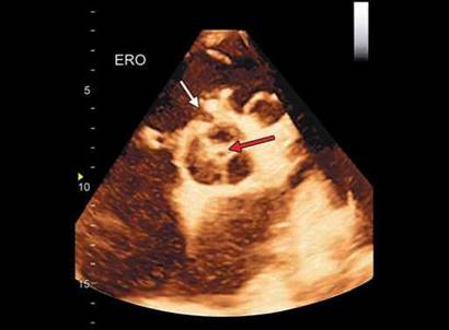
Fig. 17.33: Three-dimensional echocardiographic short-axis view showing collapsed aneurysm of aortic sinus (white arrow) with incomplete aortic valve coaptation causing regurgitant orifice (red arrow).

Fig. 17.34: Transesophageal echocardiographic midesophageal short axis showing communication between the right atrium and noncoronary aortic sinus by color flow mapping (yellow arrow). Note aneurysm of atrial septum with small jet of atrial septal defect (white arrow).

• Normal dimensions of the adjacent aortic root and ascending aorta (Table 17.1).
The above criteria differentiate the aortic sinus aneurysm from the aneurysm of the membranous septum and subannular aortic pseudoaneurysms.
Less commonly observed anomalies include pulmonary stenosis, coarctation and atrial septal defects (Fig. 17.34).
Acquired aortocameral communications can be with or without aneurysmal dilatation of the aortic sinuses (Figs 17.35A and B).
aortopulmonary window
Aortopulmonary window is defined as a communication between the ascending aorta and the pulmonary trunk, or right pulmonary artery (Fig. 17.36).
It is characterized by the presence of well-defined and separate aortic and pulmonary valve apparatuses, unlike in truncus arteriosus, where only an isolated truncal valve is noted.10
It is an uncommon entity, representing approximately 0.1% of all congenital heart disease. It is explained by incomplete fusion or malformation of right or left conotruncal rings.
Its pathophysiology shares similar hemodynamic features with patent ductus arteriosus and truncus arteriosus, and a frequent clinical manifestation is heart failure.
Types of Aortopulmonary Window
Type I or proximal communication occurs near the semilunar valves.
Type II or distal communication involves the pulmonary bifurcation at the level of the right pulmonary artery.
In type III, there is a wide communication between the aorta and pulmonary artery owing to total absence of the AP septum.
truncus arteriosus
Truncus arteriosus, also known as common arterial trunk, is characterized by a single great artery that arises from the base of the heart and supplies the systemic, coronary and pulmonary blood flow and by a VSD (Fig. 17.37).
This anomaly results from a septation failure during development of the ventricular outlets and the proximal arterial segment of the heart tube. Four types of trunks are described.

Figs 17.35A and B: Communication between left coronary sinus and the left atrium following aortic valve replacement. Transesophageal echocardiographic picture (A) with continuous wave Doppler flow across the hole.

Fig. 17.36: Type II aortopulmonary window (arrow) seen in low parasternal short-axis view with some tilt. (RVOT: Right ventricle outflow tract; MPA: Main pulmonary artery; LPA: Left pulmonary artery; RPA: Right pulmonary artery).

Fig. 17.37: Transthoracic parasternal long-axis view showing type I truncus arteriosus. Arrow points to the ventricular septal defect.
In type I, the main pulmonary trunk arises from the truncal artery just distal to the truncal valve.
In types II and III, the pulmonary trunk is absent and the right and left pulmonary branches arise posteriorly.
Type IV corresponds to pulmonary atresia with VSD and multiple major AP collateral arteries.
the presence of a common truncal valve allows differentiation from AP window, in which two separate valves are noted. The truncal valve is often abnormal, typically being stenotic or insufficient.
supravalvular aortic stenosis
Supravalvular aortic stenosis is a focal or diffuse narrowing of the aorta starting at the sinotubular junction and
often involving the entire ascending aorta (15% of cases) (Fig. 17.38).
Aortic or peripheral arterial system involvement is not common. The other entities in this group are bicuspid aortic valve, aortic coarctation and subaortic stenosis.11 Supravalvar aortic stenosis (SAS) is commonly associated with Williams-Beuren syndrome, an autosomal dominant multisystemic disorder that may manifest with SAS (71% of cases), mitral valve prolapse and pulmonary artery stenosis.
patent ductus arteriosus
The patent ductus arteriosus is a vascular structure that connects the proximal descending aorta to the roof of the

Fig. 17.38: Aortic narrowing at the sinotubular junction associated with valvular stenosis.

Fig. 17.39: Parasternal short-axis view showing patent ductus arteriosus by color flow mapping (arrow).

Fig. 17.40: Parasternal short-axis view for judging the size of ductus.
main pulmonary artery near the origin of the left branch pulmonary artery (Fig. 17.39). In the normal heart with a left-sided aortic arch, the ductus arteriosus connects the left pulmonary artery near its origin to the descending aorta just distal to the left subclavian artery.12
the physiological impact and clinical significance of the ductus depend largely on its size and the underlying cardiovascular status of the patient. The ductus may be 'silent' (not evident clinically but diagnosed incidentally by echocardiography done for a different reason), small, moderate or large.
the hemodynamic impact of ductus in an otherwise normal cardiovascular system is determined by the magnitude of shunting, which depends largely on the flow resistance of the ductus arteriosus. The length,
the narrowest diameter, and the overall shape and configuration of the ductus arteriosus determine resistance.
Increased flow returning to the left heart results in increased left atrial and left ventricular end-diastolic pressures. The left ventricle compensates by increasing stroke volume and eventually may hypertrophy to normalize wall stress.
Two-dimensional imaging demonstrates the geometry of the ductus. Color Doppler is a very sensitive modality in detecting the presence of a ductus and is frequently used to estimate the degree of ductal shunting (Fig. 17.40).
Even an extremely tiny patent ductus can be detected by a color flow signal entering the pulmonary artery near the origin of the left pulmonary artery. In patients with high pulmonary vascular resistance and ductus, with low velocity or right-to-left flow, the ductus arteriosus may be very difficult to demonstrate with color flow Doppler, even if it is large. Findings such as septal flattening, unexplained right ventricular hypertrophy and high-velocity pulmonary regurgitation should prompt a thorough investigation for a ductus.
Following device closure ofthe ductus, flow obliteration can be seen by echocardiography (Fig. 17.41).
acquired aortopathies
Marfan syndrome is a multisystemic connective tissue disorder of autosomal dominant inheritance that is characterized by skeletal, cardiovascular and ocular abnormalities.13,14

Fig. 17.41: Ductus closure device (arrow) shown as projection in pulmonary artery.

Fig. 17.42: Annuloaortic dilatation in a 27-year-old female with skeletal features of Marfan syndrome. Transthoracic echocardiographic parasternal long-axis view.
• In the 2010 revised Ghent nosology, aortic root aneurysm and ectopia lentis are cardinal features.
• In the absence of any family history, the presence of these two manifestations is sufficient for the unequivocal diagnosis of the syndrome.
• In the absence of any of these two, the presence of bonafide FBN1 mutation or a combination of systemic features is required.
• Minor criteria consist of dilatation or dissection of the descending or abdominal aorta before the age of 50 years, dilatation of the main pulmonary artery before the age of 40 years, mitral valve prolapse and calcification of the mitral annulus before the age of 40 years.
Aortic root dilatation with Z score > 2 is a major criterion (Figs 17.42 to 17.47). Cardiovascular major criteria include dilatation of the ascending aorta (involving at least the sinuses of Valsalva) with or without aortic regurgitation, as well as dissection of the descending aorta.
Marfan syndrome is caused by mutations in the fibrillin-1 gene (FBN1) on chromosome 15 (more than 135 mutations have been identified). FBN1 encodes for microfibrils that connect the elastic lamina to adjacent endothelial cells and smooth muscle cells, contribute to structural integrity, and coordinate contractile and elastic tension of the vessel wall. Dysfunction of microfibrils causes disintegration and elastolysis of the connective tissue, which ultimately result in aneurysm formation and dissection. Aortic enlargement > 4 cm or an increase in
aortic root diameter in patients with bicuspid aortic valve or Marfan syndrome is associated with a dramatic increase in risk of type A aortic dissection.15
Cardiovascular and valvular disease is seen in the majority of patients (90%) and is the dominant cause of mortality. The term annuloaortic ectasia refers to uniform dilatation of all three sinuses of Valsalva, with extension into the ascending aorta and obliteration of the normal sinotubular ridge; it is found in 60% to 80% of adults with Marfan syndrome (Figs 17.43 and 17.46).
The ectasia finally extends into the annulus, causing aortic regurgitation, which may progress to root dissection or rupture.16 With annular ectasia, the aortic valve assumes triangular shape in diastole (Fig. 17.48).
Aortic aneurysm without annuloaortic ectasia is not uncommon but is not classic of Marfan syndrome. In comparison with atherosclerotic aortic aneurysms, aortic aneurysms in Marfan syndrome commonly occur in younger patients and enlarge more rapidly. In addition, there may be a wide range of musculoskeletal manifestations, including scoliosis, chest wall deformity, arachnodactyly and acetabular protrusion.
In comparison with atherosclerotic aneurysms, the aortic aneurysms seen in Marfan syndrome rarely show intimal calcification or atherosclerotic plaques.
Aortitis is caused by several connective tissue disorders (e.g. Takayasu's arteritis, temporal arteritis, ankylosing

Fig. 17.43: Another pattern of aortic root dilatation in a patient with suspected Marfan syndrome. Transesophageal echocardiographic long-axis view.

Fig. 17.44: Tethering of the aortic valve leaflets due to root dilatation causing severe aortic valve incompetence.

Figs 17.45A and B: Type I aortic valve regurgitation (right panel) due to annular dilatation.

Fig. 17.46: Normal aortic annulus diameter (22) but dilated aortic root, effacement of sinotubular ridge and aneurysmal ascending aorta in a patient with classic Marfan syndrome.

Fig. 17.47: Suprasternal long-axis view showing dilatation of the aortic root.

Fig. 17.48: Aortic sinus dilatation causing triangular aortic valve opening in diastole.

Fig. 17.49: Circumferential wall thickening with markedly reduced lumen of left subclavian artery in an 18-year-old young girl with Takayasu arteritis. Arrow points to the residual lumen.
spondylitis, relapsing polychondritis) and infections (e.g. bacterial endocarditis, syphilis, Rocky Mountain spotted fever, fungal infections). It is also a feature of Cogan's syndrome (inflammatory keratitis, vestibular and auditory dysfunction, and aortitis).
Takayasu arteritis is a primary large-vessel arteritis of unknown origin that affects the aorta and its main branches mainly in tropical countries.17
It basically affects young women (80-90% of patients with Takayasu arteritis are female and in the second or third decade of life).
Echocardiography demonstrates aortic luminal changes including stenosis, dilatation and aneurysm.
Furthermore, axial images demonstrate circumferential wall thickening of the aorta and its involved branches, thus allowing detection of Takayasu arteritis in the early systemic phase, when inflammation or thickening of the vessel wall may already be seen in the absence of luminal abnormalities (Figs 17.49 to 17.51).
Left subclavian artery involvement is a major criterion especially in females below the age of 40 years.
The Numano classification is based on the involved anatomy.
• Type I: Involvement of only the branches of the aortic arch (Figs 17.50 and 17.51).
• Type IIa: Involvement of the ascending aorta or the aortic arch with or without branches.
• Type IIb: Involvement of the descending thoracic aorta with or without the ascending aorta or the aortic arch with its branches.
• Type III: Involvement of the entire descending aorta with or without the renal arteries.
• Type IV: Involvement of only the abdominal aorta with or without the renal arteries.
• Type V: Involvement of the entire aorta with branches. Involvement of the coronary or pulmonary arteries
should be indicated.
Atherosclerosis and Degeneration of Aorta
Echocardiography is commonly used to detect aortic atheroma. The presence of detectable atherosclerotic plaques in the aorta indicates the presence of atherosclerotic disease and is a possible source of embolism.18
Atherosclerosis of the aorta is an independent predictor of long-term neurological events and mortality.19-22
Presence of plaque is defined as visible thickening of the aortic wall (Figs 17.52 and 17.53). Maximal plaque thickness and the maximal circumferential extent of atheroma is measured in each segment.
The type of aortic atheromatous plaque is classified simple or complex and also calcified or noncalcified. TEE characterizes the plaque by assessing plaque thickness, ulceration, calcification and superimposed mobile thrombi, thereby determining the embolic potential of
each plaque.21,22
The grading of aortic atheroma is as follows:
• Normal aorta (no intimal thickening).
• Mild atherosclerosis (< 3 mm intimal thickening without intimal irregularities).
• Moderate aortic atherosclerosis (intimal thickening > 3 mm, with diffuse irregularities and/or calcification).

Fig. 17.50: Longitudinal view of the right common carotid artery showing markedly thickened walls (arrows).

Fig. 17.51: Duplex scan of the left common carotid artery with color Doppler. Markedly reduced lumen in the middle with circumferential diffuse wall thickening (arrows).

Fig. 17.52: Transesophageal echocardiographic short-axis view of descending thoracic aorta showing mild circumferential diffuse intimal thickening (Grade II atheroma).

Fig. 17.53: Transesophageal echocardiographic longitudinal view of the ascending aorta showing diffuse intimal thickening.
• Severe atherosclerosis (> 5 mm intimal thickening and one or more of the following: large protruding or mobile atheromatous debris, ulcerated plaques and/ or thrombi).
Some have described mobile atheromas as Grade V with highest embolic potential.21
Atherosclerotic plaques are defined as complex in the presence of protruding atheromas of > 4 mm in thickness, mobile debris or the presence of plaque ulceration (Figs 17.54 and 17.55).
ttere is a strong association between aortic stenosis and aortic atherosclerosis.
Presence of ulcerated plaques in the ascending aorta and/or the aortic arch is associated with a significantly greater prevalence of cerebral embolic events than that in the absence of such plaques (Figs 17.55 and 17.56).
Diseases of aorta that present with acute severe chest or back pain with hemodynamic impairment are collectively labeled as acute aortic syndrome. ttese include:4,23

Fig. 17.54: Grade III atheroma in the aortic arch. There is localized thickening with no calcification.

Fig. 17.55: Calcified atheromatous ulcer in anterior wall of the ascending aorta close to sinotubular junction with protrusion (arrow).
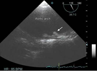
Fig. 17.56: Grade IV atheroma in the aortic arch with penetrating ulcer. Note the ulcerated plaque with a crater (arrow).

Fig. 17.57: A 12-year-old boy with aneurysm of aortic root. Although the root diameter is only 3.8 cm, Z score is > 2.
• Aortic dissection.
• Intramural hematoma.
• Impending rupture of aortic aneurysm.
• Penetrating atheromatous ulcers.
• Traumatic transection of aorta.
Disease processes affecting the ascending and arch aorta include degenerative aneurysms and aneurysms associated with connective tissue disease, as well as acute aortic dissection and its variants of intramural hematoma and penetrating ulcer.
An aortic aneurysm is a general term for any dilation of the aorta to > 1.5-times normal, usually representing
an underlying weakness in the wall of the aorta at that location (Fig. 17.57).
The most common acquired condition predisposing patients to dissection is chronic hypertension, which is present in 75% of cases.24
Elevated arterial pressure leads to intimal thickening, fibrosis and calcification. This limits blood supply to the arterial wall. In addition, the extracellular matrix is modified with enhanced apoptosis and elastolysis.
Atherosclerosis leads to adventitial fibrosis and compromise of the vasa vasorum—the small vessels that penetrate into the vessel wall.
All of the above lead to necrosis of the smooth muscle cells and fibrosis of elastic structures in the media, resulting in stiffness, weakness and a vulnerability to shear

Fig. 17.58: Transthoracic echocardiographic parasternal long-axis view showing aneurysm of the descending thoracic aorta behind left atrium.

Fig. 17.59: Aortic dissection confined to ascending aorta.

Fig. 17.60: Dissecting aneurysm confined to descending thoracic aorta and below.

Fig. 17.61: Dissecting aneurysm spreading down and upward from the arch of aorta.
forces. With time, this leads to aneurysmal dilation and dissection.25
Morphologically, aneurysms are classified into three types.26
1. Fusiform (spindle-shaped), which involve the entire circumference of the aorta (Fig. 17.58).
2. Sacciform, which are characterized by a pouchlike protrusion from a narrow opening in the aortic wall.
3. Dissecting aorta, which is characterized by intramural separation, usually within the medial layer.
Two commonly used classification for aortic dissection
are that by DeBakey and by Stanford University.27,28 There are some differences between the two, which are shown graphically in Figures 17.59 to 17.61.
In the Stanford system, type A dissections involve the ascending aorta, while type B dissections involve only the descending aorta.
In the DeBakey classification system, a type I dissection involves the entire aorta, while a type II dissection involves only the ascending aorta and a type III dissection involves only the descending aorta.
Of all aortic dissections, 50% are type I, 35% are type II and 15% are type III.

Fig. 17.62: Graphical representation of aortic dissection.

Fig. 17.63: Apical three-chamber view showing intimal flap in ascending aorta.
the importance of aortic diameter in determining risk for complications has been demonstrated in numerous studies. the normal ascending aortic diameter is 2-3 cm depending on patient age, size and sex. the risk for aortic rupture, dissection or death for the ascending aorta relative to absolute size has been well characterized with rupture reaching up to 10% per annum in case the diameter exceeds 6 cm. An aneurysm > 5 cm diameter warrants intervention.23
Aortic dissection occurs when a tear in the inner wall of the aorta causes blood to flow between the layers of the wall of the aorta, forcing the layers apart. the dissection typically extends anterograde, but can extend retrograde from the site of the intimal tear.
Because mechanical stress in the aortic wall is proportional to blood pressure and vessel diameter, hypertension and aortic dilation are known risk factors for dissections.
Most aortic dissections occur with a transverse tear along the greater curvature of the aorta a few centimeters above the aortic valve (Fig. 17.62).
Type A aortic dissection, defined here as the presence of dissection proximal to the left subclavian artery, represents a true cardiac surgical emergency (Figs 17.63 and 17.64). Its mortality if left untreated has been estimated from classical studies at 1% per hour for the first 48 hours and can result in a mortality rate exceeding 80% in the first month. Pericardial tamponade is the most common cause of death from aortic dissection.
As blood flows down the false lumen, it may cause secondary tears in the intima. trough these secondary tears, the blood can re-enter the true lumen (Fig. 17.64).
Entry tear size is of major prognostic significance since it causes greater inflow volume into the false lumen, which may increase its diastolic pressure and lead to an increase in wall stress and, consequently, a greater risk of aortic dilatation or rupture.
Classic aortic dissection is a longitudinal split or partition in the media of the aorta. An intimal tear connects the media with the aortic lumen, and an exit tear creates a true and a false lumen. the smaller true lumen is lined by intima, and the false lumen is lined by media. Typically, flow in the false lumen is slower than in the true lumen, and the false lumen often becomes aneurysmal when subjected to systemic pressure (Figs 17.65A and B).
• Usually smaller than the false lumen.
• Shows systolic expansion (false lumen shows systolic compression).
• Systolic antegrade flow by Doppler.
• No thrombus.
• Brisk contrast flow.
• Flow from true to false lumen in systole through the communication.
the TEE is an excellent test in the diagnosis of aortic dissection, with a sensitivity of up to 98% and a specificity of up to 97%.29 It has become the preferred imaging modality for suspected aortic dissection. It is especially good in

Fig. 17.64: Transesophageal echocardiographic view showing waving intimal tear in ascending aorta with a hole.

Figs 17.65A and B: Transesophageal echocardiographic midesophageal short-axis view showing true lumen (TL) and the false lumen (FL). (B)shows flow in the true lumen.
the evaluation of aorta in the setting of ascending aortic dissection, and to determine whether the ostia (origins) of the coronary arteries are involved.
In addition, TEE has also an important role in the follow-up of patients with aortic dissection as it shows the structure of the dissection, surgical repair, healing of the dissection and obliteration of the false lumen, or blood flow dynamics in true and false lumina (Figs 17.66 and 17.67).
ttree-dimensional TTE/TEE provides additional information to 2D TTE/TEE in aortic dissection assessment, particularly in entry tear size quantification. Agreement between entry tear area defined by 3D TEE and computed tomography is excellent. ttree-dimensional TEE permits better morphological and dynamic understanding of aortic
dissection when the flap is spiroidal. ttis technique may be particularly useful in the indication and monitoring of surgical or endovascular treatment of aortic dissection.
In the ascending aorta, particularly when dilated, linear reverberation images are very common, being observed in 44-55% of studies and must not be confused with dissection flaps. ttree-dimensional TEE helps to identify these artifacts (Fig. 17.68).
In approximately 13% of aortic dissections, there is no evidence of an intimal tear. It is believed that in these cases, the inciting event is an intramural hematoma (caused by hemorrhage within the media). Since there

Fig. 17.66: High transesophageal echocardiographic view showing dissection in ascending aorta.
(FL: False lumen; TL: True lumen).

Fig. 17.67: High transesophageal echocardiographic view showing dissection in ascending aorta. Flow moving into false lumen during systole. (FL: False lumen; TL: True lumen).

Fig. 17.68: Full volume three-dimensional transthoracic echocardio- graphic imaging of the ascending aorta.

Fig. 17.69: Intramural hematoma (IMH) in the arch of aorta.
is no direct connection between the true lumen and the false lumen in these cases, it is difficult to diagnose an aortic dissection. An aortic dissection secondary to an intramural hematoma should be treated the same as one caused by an intimal tear.30
Intramural hematoma is characterized by circular or crescentic thickening of the aortic wall > 5 mm (Fig. 17.69).
Inner margin of intramural hematoma is smooth, and aortic thickening occurs beneath the bright echo-dense intima, whereas an irregular margin with dilated aorta is commonly observed in patients with aneurysmal dilatation and mural thrombi. Intramural hematoma is quite easily differentiated from classical aortic dissection with flow in two lumina.30
Penetrating aortic ulcer presents as an image of craterlike outpouching with jagged edges in the aortic wall, generally associated with extensive aortic atheromas31 (Fig. 17.70).
True Versus False Aneurysms of Aorta
Thoracic aortic aneurysms can be broadly divided into true aneurysms and false aneurysms (pseudoaneurysms). True aneurysms contain all three layers of the aortic wall (intima, media and adventitia), whereas false aneurysms have fewer than three layers and are contained by the adventitia or periadventitial tissues (Figs 17.71 to 17.73).

Fig. 17.70: Penetrating ulcer in the arch.

Fig. 17.71: Pseudoaneurysm (A) of descending thoracic aorta with a narrow neck (arrow). Note the presence of thrombus in the pseudoaneurysm.

Fig. 17.72: Pseudoaneurysm containing thrombus and no apparent communication with the thoracic aorta.

Fig. 17.73: To-and-fro flow across the neck of the pseudoaneurysm.
In summary, aorta needs greater attention by those performing echocardiography. It is therapeutically and prognostically important in a large number of conditions. Aortic degenerative diseases are likely to increase with increased longevity and ever-increasing diabetes and hypertension. THE remains an initial screening technique and TEE should be performed with reasonable suspicion of aortic dissection or penetrating ulcer. Both techniques can be used for imaging surveillance as well as for follow-up of patients after endovascular repair and surgery.
n references
1. Lehmann ED, Hopkins KD, Gosling RG. Aortic compliance measurements using Doppler ultrasound: in vivo biochemical correlates. Ultrasound Med Biol. 1993;19(9):683-710.
2. Roman MJ, Devereux RB, Kramer-Fox R, O'Loughlin J. Two-dimensional echocardiographic aortic root dimensions in normal children and adults. Am J Cardiol. 1989;64(8): 507-12.
3. Vasan RS, Larson MG, Levy D. Determinants of echocardiographic aortic root size. The Framingham Heart Study. Circulation. 1995;91(3):734-40.
4. Evangelista A, Flachskampf F, Erbel R, et al. Echocardiography in aortic diseases. EAE recommendations for clinical practice. Eur J Echocardiogr. 2010;11:645-58.
5. Nistri S, Grande-Allen J, Noale M, et al. Aortic elasticity and size in bicuspid aortic valve syndrome. Eur Heart J. 2008;29: 472-9.
6. Schaefer BM, Lewin MB, Stout KK, et al. the bicuspid aortic valve: an integrated phenotypic classification of leaflet morphology and aortic root shape. Heart. 2008;94:1634-8.
7. Matsui H, Adachi I, Uemura H, et al. Anatomy of coarctation, hypoplastic and interrupted aortic arch: relevance to interventional/surgical treatment. Expert Rev Cardiovasc tter. 2007;5(5):871-80.
8. Sandhu SK, Pettitt TW. Interrupted Aortic Arch. Curr Treat Options Cardiovasc Med. 2002;4(4):337-40.
9. Kirklin JW, Barratt-Boyes BG. Congenital aneurysm of the sinus of Valsalva. In: Cardiac surgery. Morphology, diagnostic criteria, natural history, techniques, results, and indications, 2nd edition. New York, NY: Churchill Livingstone; 1993. p. 826.
10. Feldman DN, Roman MJ. Aneurysms of the sinuses of Valsalva. Cardiology. 2006;106(2):73-81.
11. Aboulhosn J, Child JS. Left ventricular outflow obstruction: subaortic stenosis, bicuspid aortic valve, supravalvar aortic stenosis, and coarctation of the aorta. Circulation. 2006;114(22):2412-22.
12. Fisher RG, Moodie DS, Sterba R, et al. Patent ductus arteriosus in adults-long-term follow-up: nonsurgical versus surgical treatment. J Am Coll Cardiol. 1986;8(2): 280-4.
13. Dean JC. Marfan syndrome: clinical diagnosis and management. Eur J Hum Genet. 2007;15(7):724-33.
14. Nollen GJ, Groenink M, Tijssen JG, et al. Aortic stiffness and diameter predict progressive aortic dilatation in patients with Marfan syndrome. Eur Heart J. 2004;25(13):1146-52.
15. Milewicz DM, Dietz HC, Miller DC. Treatment of aortic disease in patients with Marfan syndrome. Circulation. 2005;111(11):e150-7.
16. El Khoury G, Glineur D, Rubay J, et al. Functional classification of aortic root/valve abnormalities and their correlation with etiologies and surgical procedures. Curr Opin Cardiol. 2005;20:115-21.
17. Mishra A, Bhaktarahalli JN, Ehtuish EF. Takayasu arteritis diagnosed by 16-row multidetector CT angiography. Neurosciences (Riyadh). 2007;12(1):73-5.
18. Tunick PA, Kronzon I. Atheromas of the thoracic aorta: clinical and therapeutic update. J Am Coll Cardiol. 2000;35(3):545-54.
19. Montgomery DH, Ververis JJ, McGorisk G, et al. Natural history of severe atheromatous disease of the thoracic aorta: a transesophageal echocardiographic study. J Am Coll Cardiol. 1996;27(1):95-101.
20. Di Tullio MR, Russo C, Jin Z, et al. Aortic arch plaques and risk of recurrent stroke and death. Circulation. 2009;119(17): 2376-82.
21. Katz ES, Tunick PA, Rusinek H, et al. Protruding aortic atheromas predict stroke in elderly patients undergoing cardiopulmonary bypass: experience with intraoperative transesophageal echocardiography. J Am Coll Cardiol. 1992;20(1):70-7.
22. Zaidat OO, Suarez JI, Hedrick D, et al. Reproducibility of transesophageal echocardiography in evaluating aortic atheroma in stroke patients. Echocardiography. 2005;22: 326-30.
23. Meredith EL, Masani ND. Echocardiography in the emergency assessment of acute aortic syndromes. Eur J Echocardiogr. 2009;10(1):i31-9.
24. Agmon Y, Khanderia BK, Meissner I, et al. Independent association of high blood pressure and aortic atherosclerosis. A population-based study. Circulation. 2000;102: 2087-93.
25. Hagan P, Nienaber CA, Isselbacher EM, et al. the International registry of acute aortic dissection. New insights into and old disease. JAMA. 2000;283:897.
26. Erbel R, Engberding R, Daniel W, et al. Echocardiography in diagnosis of aortic dissection. Lancet. 1989;1(8636):457-61.
27. DeBakey ME, Henly WS, Cooley DA, et al. Surgical management of dissecting aneurysms of the aorta. J ttorac Cardiovasc Surg. 1965;49:130-49.
28. Daily PO, Trueblood HW, Stinson EB, et al. Management of acute aortic dissections. Ann ttorac Surg. 1970; 10(3): 237-47.
29. Shiga T, Wajima Z, Apfel CC, et al. Diagnostic accuracy of transesophageal echocardiography, helical computed tomography, and magnetic resonance imaging for suspected thoracic aortic dissection: systematic review and meta-analysis. Arch Intern Med. 2006;166(13):1350-6.
30. Pepi M, Campodonico J, Galli C, et al. Rapid diagnosis and management of thoracic aortic dissection and intramural haematoma: a prospective study of advantages of multiplane vs biplane transoesophageal echocardiography. Eur J Echocardiogr. 2000;1:72-9.
31. Vilacosta I, San Roman JA, Aragoncillo P, et al. Penetrating atherosclerotic aortic ulcer: documentation by transesophageal echocardiography. J Am Coll Cardiol. 1998;32:83-9.