Aortic valve guards the left ventricular outflow tract (LVOT) and is responsible for unidirectional flow into the aorta. It is a three-leaflet valve with three components: annulus, leaflets and commissures. In individuals with normal aortic valves, the valve area is 3.0-4.0 cm* 1 2 3. As aortic stenosis develops, minimal valve gradient is present until the orifice area becomes less than half of normal. The pressure gradient across a stenotic valve is directly related to the valve orifice area and the transvalvular flow.
Aortic valve stenosis (AS) is the commonest valve disorder encountered in clinical practice. Typically, severe aortic stenosis is the one with a peak transaortic velocity of > 4 m/s, mean gradient of > 40 mm Hg and aortic valve area (AVA) of < 1.0 cm* 1 2 3. However, AS is a diverse disorder wherein flow, Д pressure and area frequently do not match. A number of factors affect the total hemodynamic burden imposed by AS on the left ventricle (LV). There is no gold standard for AVA. Comorbidities that affect flow and Д pressure are frequent. Conventional assessment of AS with echocardiography could be erroneous because of geometric assumptions and Doppler phenomena like pressure recovery. Functional anatomy of the aortic valve complex is important for decision making. Understanding the true nature of AS helps in better management of patients.

ANATOMY OF TRILEAFLET AORTIC VALVE
The aortic valve functions to prevent the regurgitation of blood from the aorta into the LV during ventricular diastole and to allow the appropriate flow of blood from the LV into the aorta during ventricular systole. The aortic valve has three principle components1-3 (Figs 5.1 and 5.2).
1. Annulus
2. Cusps
3. Commissures.


The aortic valve annulus is a fibrous structure lying at the level of the junction of the aortic valve and the ventricular septum, which is the nadir of the aortic valve complex. This area provides structural support to the aortic valve complex. The annulus is shaped like a crown and extends to the level of the aortic sinuses. It attaches to the aortic media distally and the membranous and muscular ventricular septum proximally and anteriorly (Fig. 5.3).

There are three aortic valve cusps, each semilunar in appearance. A small dilatation of the proximal aorta is associated with each cusp (sinus of Valsalva or aortic sinus). tteir association with the respective coronary ostia identifies them: left, right and posterior (or noncoronary). In the normal human heart, the left and right coronary arteries originate from the left and right aortic sinuses.
In about 10% of cases, coronary artery origins occur above the sinotubular junction. The aortic sinuses share the same histological characteristics of the aortic wall: tunica intima, tunica media and tunica adventitia; however, the bases of the left and right sinuses are primarily composed of ventricular musculature, whereas the base of the noncoronary sinus is solely fibrous tissue. This is a consequence of the shared fibrous skeleton between the aortic and mitral valve structures.
the right and left cusps are usually equal in size, with the posterior cusp being slightly larger (Fig. 5.4).
Each cusp has two free edges, both shared with the adjacent cusps. At the center of each free edge is a small fibrous bulge named the nodule ofArantius. ttese nodules are located at the contact site of valve cusp closure. The rim of each valve cusp is slightly thicker than the cusp body and is known as the lunula. the lunulae of adjacent cusps slightly overlap each other at the time of valve closure, serving a role of increased valve support. The lunula can have fenestrations, most often located adjacent to the commissures; however, these are also not of clinical consequence (Fig. 5.5).


Commissures
Each cusp is attached to the wall of the aorta by the outward edges of its semicircular border. The level at which this attachment occurs is known as the sinotubular junction and is the functional level of the aortic valve orifice. A line of demarcation known as the supra-aortic ridge identifies the sinotubular junction.
the small spaces between each cusp's attachment point are called the aortic valve commissures. The three commissures lie at the apex of the annulus and are equally spaced around the aortic trunk. The commissures are composed of collagenous fibers oriented in a radial fashion that penetrate into the aortic intima and are anchored in the media of the aorta. This configuration provides optimal support to valvular structure, with stress on the valve cusps being transmitted into the aortic wall. The commissure between the left and posterior cusp is located at the right posterior aspect of the aortic root, whereas the commissure between the right and noncoronary cusp is located at the right anterior aspect of the aortic root.
Etiology of Aortic Stenosis
• Congenital aortic stenosis
• Calcification of bicuspid valve in middle age
• Postinflammatory fibrocalcific disease (rheumatic)
• Degeneration of aging valve
• Calcification of unicuspid valve
• Other rare causes like ochronosis, alkaptonuria, lupus, and so on.
unicuspid aortic valve4
Unicuspid aortic valve is a congenital valvular defect with an incidence of 0.02% in the general population. It is commonly associated with clinically significant aortic stenosis, usually manifesting during the third decade of life. All valves are unicommissural with the posterior commissural attachment. The free edge of the valve extends from the single commissure without further communication with the aorta (Figs 5.6 and 5.7).
An estimated 50% of individuals with unicuspid aortic valve have associated ascending aortic dilatation. This is a rare cardiac anomaly presenting at a young age with clinically significant aortic stenosis.
Bicuspid aortic valve is the most common congenital cardiac anomaly, occurring in 1-2% of the population, with a 2:1 male predominance. Evidence exists of familial clustering, with the incidence as high as 10% in some families. Bicuspid aortic valve may be clinically silent but can lead to early development of aortic stenosis or aortic insufficiency, most commonly in the fifth and sixth decades of life.


Conditions associated with bicuspid aortic valve include:
• Patent ductus arteriosus
• Williams syndrome
• Turner syndrome
• Coarctation of aorta
• Aortic root dilatation and ascending aortic aneurysm The larger leaflet is referred to as the conjoined leaflet
(Fig. 5.8).
Two commissures (or hinge points) are present; usually, neither is partially fused. The presence of a partially fused commissure, which has also been called a high raphe, probably predisposes toward eventual stenosis. At least half of all congenitally bicuspid valves have a low raphe, which never attains the plane of the attachments of the two commissures and never extends to the free margin of the conjoined cusp (Figs 5.9 and 5.10).

Valve leaflet orientation and morphology can vary. Fusion along the right or left leaflets is less commonly associated with stenosis. Fusion along the right and noncoronary leaflets is more frequently associated with pathological changes of stenosis.
QUADRICUSPID AORTIC VALVE
The incidence of quadricuspid aortic valve (QAV) is estimated at 0.0125-0.033% in the general population.6 Seven different subtypes of QAV have been identified, with the most common being three cusps of equal size with a fourth smaller cusp (Fig. 5.11).
Quadricuspid valve most commonly occurs as an isolated defect but has been associated with patent ductus arteriosus, Ehlers-Danlos syndrome, hypertrophic obstructive cardiomyopathy and subaortic stenosis (SAS). Aortic valvular insufficiency is commonly observed in this anomaly. It occurs secondary to a central orifice formed from malcoaptation of the four valvular leaflets.7
ANATOMY OF AORTIC STENOSIS
Aortic valve stenosis is the functional narrowing of the orifice of the aortic valve due to the following pathology:8
• Thickening of the leaflets from base to free margins
• Shortening of the leaflets
• Commissural fusion (Figs 5.12 and 5.13)
• Dystrophic calcification (Fig. 5.14)
• Hypoplastic annulus in congenital aortic stenosis The congenitally stenotic aortic valve may be acommissural, unicommissural, bicuspid or rarely, congenitally quadricuspid/quadricommissural.9


the presence of one, two or four cusps instead of three is associated with abnormal valve hemodynamics and produces greater and earlier leaflet damage (Fig. 5.14).
PLANIMETRY OF THE AORTIC VALVE AREA IN AORTIC STENOSIS
Planimetry is the tracing out of the opening of the aortic valve in a still image obtained during echocardiographic acquisition during ventricular systole, when the valve is supposed to be open. While this method directly measures the valve area, the image may be difficult to obtain due to artifacts during echocardiography, and the measurements are dependent on the effort undertaken to manually trace the perimeter of the open aortic valve right at its tip

(Fig. 5.15). Craniocaudal motion of the leaflets causes echo dropouts. Because of these reasons, planimetry of aortic valve is not routinely performed.
Major limitations are:
• Difficulty in obtaining oblique cuts to profile the orifice in two-dimensional (2D) echocardiography
• Heavy calcification hampering border detection
• Phasic cranial motion of the cusps during systole
• Inability to get minimal cross-sectional area due to slice thickness artifact.
Usually, transesophageal echocardiography (TEE) is better than transthoracic echocardiography (TTE) for planimetry of AVA.10 However, accuracy of 2D TEE method may also be limited by difficulties in obtaining the correct cross-sectional view at the level of the edges of the aortic cusps.11
Planimetry of AVA by TTE/TEE is difficult and less accurate than the continuity equation for assessing the severity of aortic stenosis. It is usually over-estimated (because it is geometric area and not flow cross-sectional area) but can be used in noncalcific mild or moderate AS. Some have reported good success in obtaining valve area in severe cases and irregular valves by three-dimensional (3D) TTE12 (Fig. 5.16).
Development of real-time 3D TEE has allowed volumetric data acquisition of the aortic valve, from which the true orthogonal 2D cut plane of the aortic cusps can be extracted for the accurate determination of the AVA (Fig. 5.17). This method has more accuracy but is timeconsuming.

HEMODYNAMICS OF AORTIC VALVE STENOSIS
Normal AVA in adults is 3-4 cm2, and in children it is about 1.7 cm2/m2. With development of orificial narrowing, valve offers resistance to transvalvular flow. To maintain transvalvular flow, the LV generates greater pressure during systole (Fig. 5.18). This results in development of transaortic pressure gradients (AP). AP increases with increasing severity of aortic stenosis but in a curvilinear fashion (Fig. 5.19). The presence of an obstruction results in both turbulent flow and increased velocity, two characteristics readily detected by Doppler echocardiography.13,14 Because of the large gradient, the pressures within the LV rise significantly and left ventricular hypertrophy results. AVA is relatively flow- independent and hence preferred over the velocity and pressure gradients for judging severity of AS.15
Complete assessment of the degree of aortic stenosis requires:
• Measurement of the transvalvular flow
• Determination of the transvalvular pressure gradient
• Calculation of the AVA
• Calculation of energy loss coefficient
• Calculation of valvuloarterial impedance Conventionally, severity of AS is judged by the above parameters using criteria shown in Table 5.1:1617
• Stroke volume (SV) is measured by multiplying LVOT cross-sectional area by the velocity-time integral of the outflow. SV should be indexed for body surface area (Fig. 5.20).


• LVOT diameter is measured from parasternal long-axis view in mid-systole and area is estimated by assuming it to be circular (Fig. 5.21).
• Transaortic flow rate is calculated by dividing SV by systolic ejection time.
• Aortic valve area is calculated by dividing SV by aortic velocity-time integral (Fig. 5.21).
• Valve resistance is calculated by dividing mean transaortic gradient by transaortic flow rate.18
• Substituting the Doppler-derived SV by SV directly obtained with real-time 3D echocardiography, which considerably simplifies the calculation, overcomes many potential sources of error, and does not depend on the quality of the parasternal acoustic window.19
• Echo-2D underestimates the LVOT area, which may explain the tendency of Echo-2D to estimate a smaller AVA than Echo-3D.
• Stroke volume index is the only independent predictor of the difference in AVA between invasive and noninvasive assessments.

technical tips
• The most common windows used for recording peak aortic systolic velocity are the apical, suprasternal and right parasternal. A comprehensive Doppler examination for aortic stenosis requires that the ascending aorta be examined from all possible windows in order to align the beam parallel to the jet (Figs 5.22 and 5.23).
• A potential source for error is mistakenly interpreting the profile of mitral regurgitation for that of aortic stenosis in apical windows. However, AS signal begins after the isovolumic contraction and is slightly delayed (Fig. 5.24).
• The CW spectrum profile can help in differentiating mild aortic stenosis from the severe one. As the severity increases, peak of ДР gets delayed and occurs in later part of systole (Figs 5.25 and 5.26).
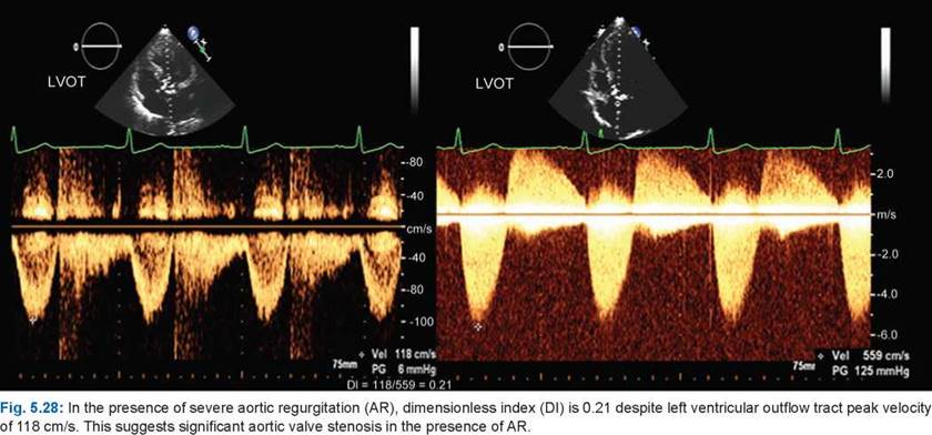
• Whenever there is doubt about the quality of parasternal long-axis measurement of the LVOT or there is associated aortic or mitral regurgitation (making continuity equation nonapplicable), it is prudent to use a dimensionless index of ratio of LVOT peak velocity to transaortic peak velocity (Figs 5.27 and 5.28). An index of < 0.25 usually denotes severe aortic valve stenosis. However, in low-flow situations, it may not differentiate true from pseudostenosis.
• The weakest aspect of area calculation is the variability in measurement of LVOT area, because it involves squaring the LVOT dimension. The other weak point is some flow-dependency of the AVA by the continuity equation.20


• Geometry of the aortic orifice, inflow and the size of aorta all affect estimation of the AVA by the continuity equation (Fig. 5.29).
• It has been suggested that estimation of energy loss index (ELI) is a better guide for severity and prognosis of AS than the AVA.21 Figure 5.30 shows the method to estimate ELI. Energy loss index takes into account the pressure recovery (Fig. 5.31). the valves with the greatest pressure recovery have the least energy loss.
• Another method to assess hemodynamic burden of aortic stenosis is estimation of ventriculovalvular impedance (VVI). VVI is the ratio of arterial systolic pressure + mean transaortic gradient divided by the SV index.22 A value of > 4.5 is significant VVI. VVI takes into account the hemodynamic load on the LV imposed by systemic hypertension and also corrects for the lower ДР seen in patients with low flow (reduced SV index). It is possible to use VVI regardless of ejection fraction (Fig. 5.32).
• Percent stroke work loss calculated as mean systolic pressure gradient divided by mean ventricular systolic pressure x 100% is also a good parameter of AS severity.
• A simplified continuity equation that provides AVA is a product of dimensionless index and LVOT crosssectional area (Fig. 5.33).


Fig. 5.33: Modified continuity equation for estimating aortic valve area. Flow (area x velocity) is constant across a stream if there is no sump or sink.
• If dynamic obstruction creates difficulty in estimating LVOT SV, the right ventricular outflow tract SV can be used as the numerator.
low-gradient, low-flow aortic VALVE stenosis
Low-gradient low-flow aortic stenosis is characterized by AVA < 1.0 cm2, mean gradient < 30 mm Hg and SV index < 35 mL/m2 (Figs 5.34 to 5.36).

Fig. 5.32: Systolic aortic pressure recovers in divergence zone with decrease in mean gradient. Combination of systolic aortic pressure and mean transaortic gradient represents the pressure load to be overcome by the left ventricle (LV) during ejection. When this is divided by the stroke volume index, it is akin to total resistance faced by the LV.
Flowchart 1: Representation of low-flow low-gradient aortic stenosis

Types of Low-Gradient Low-Flow Severe Aortic Valve Stenosis
Schematic diagram of low-flow low-gradient AS is shown in Flowchart 1.
Calculation of AVA by continuity equation is flow- dependent and in presence of low flow, one estimates much smaller AVA due to boundary effects.
• About 30% of all patients have AVA in the severe range with low flow or low gradients or both.
• Low-flow low-gradient AS may truly have severe AS with resultant myocardial failure (true AS) or may have more moderate degrees of AS and unrelated myocardial dysfunction.23,24
• In patients with true AS, increased flow (as with dobutamine infusion) across a fixed valve orifice results in increased transvalvular flow velocity and gradients, without a change in calculated valve area (Fig. 5.37A and B).

Fig. 5.34: Low-gradient and low-flow aortic valve stenosis with mean gradient of 17 mm Hg and stroke volume of 20 mL/M2.

Fig. 5.35: Calculated aortic valve area of 0.5 cm2 in a patient with pseudosevere aortic valve stenosis (AS) with a peak transaortic velocity of 212 cm/s. CW Doppler pattern (left panel) shows early systolic peaking suggesting that the AS is not severe.

Fig. 5.36: Low-flow (stroke volume index—30 mL/m2) despite adequate left ventricular outflow tract diameter.
• In the setting of pseudo-AS, the augmented flow results in only a mild increase in transvalvular gradient and an increase in valve area by > 0.2 cm2.
• As many as 30% of patients with low-flow low-gradient AS fail to augment SV by at least 20% with dobutamine infusion; these patients are denoted as having no
contractile reserve.23,24 Such patients have higher operative mortality.
• Majority of patients with low-gradient low-flow AS have significant valve stenosis.
• The differentiation between true and pseudo-AS may be improved by using other noninvasive parameters, such as the projected valve area at a normal flow rate, an echocardiographic method that attempts to control

Figs 5.37A and B: (A) Baseline left ventricular outflow tract and transaortic velocities and calculated aortic valve area at baseline at heart rate of 69/min in a low-flow, low-gradient aortic valve stenosis (AS) patient. (B) At 20 ^g/kg/min dobutamine infusion and heart rate of 113/minute. There is 20% increase in stroke distance and 27% increase in transaortic velocity without any change in aortic valve area suggesting that it is true severe AS despite a mean gradient of 24 mm Hg at rest.
for the variable augmentation of transaortic flow induced by dobutamine.25
• ttere is a good correlation between calcium and severity. Calcified valves usually have severe AS.
• Planimetry, when possible, can accurately tell about anatomical area, which in general is no greater than 20% when compared to the effective orifice area.
paradoxical low-flow as with preserved ejection fraction
• As many as 35% of patients with severe AS (AVA
< 0.6 cm/m2) and preserved ejection fraction (> 50%) have paradoxically low flow, defined as a SV index of
< 35 mL/m2.26
• the mechanism of the paradoxically low flow in the face of preserved ejection fraction likely relates to high afterload, and the reduced SV in this setting is an early marker of intrinsic myocardial dysfunction.
• Such cases can be identified by small LV cavity with marked hypertrophy (Fig. 5.36).
• Paradoxical low-flow AS has variable prognosis.
• 3D THE or TEE Planimetry of AVA may better define the severity of AS in these patients.
subaortic stenosis
Discrete fixed SAS has hemodynamic consequences like valvular AS (Figs 5.38 to 5.40). It is known for its sometimes rapid hemodynamic progression in childhood. In contrast to children, fixed SAS progresses slowly in adulthood. Discrete subaortic membrane accounts for 8-10% of all cases of LVOT obstruction in children.27,28
there are three types of SAS identified by echocardiography:
1. Discrete membranous ring
2. Discrete fibromuscular stenosis
3. Diffuse tubular stenosis Pathoanatomically, it is of four types:29
1. Short segment SAS
2. Long segment SAS
3. Posterior displacement of infundibular septum
4. Accessory tissue of membranous septum obstructing the LVOT
SAS presents as a membranous or fibromuscular ring below the aortic valve, either in isolation or in association with other congenital anomalies such as ventricular septal defect, patent ductus arteriosus, coarctation of the aorta, bicuspid aortic valve, abnormal left ventricular papillary muscle, atrioventricular septal defect and persistent superior left vena cava.
the jet from the narrowed subaortic tract damages the aortic cusps and causes regurgitation, which is present in 20% of the cases.
Aortic regurgitation is a common consequence of discrete SAS and the “prevention” of progressive aortic regurgitation by early operation has been advocated.
Hemodynamically, SAS is characterized by unusually higher gradients due to hole-in-diaphragm or tubular architecture with much greater pressure recovery.

Fig. 5.38: Membranous subaortic stenosis (arrow) shown in parasternal long-axis view with peak velocity exceeding 7 m/s and mild aortic valve regurgitation (right panel).
(RVOT: Right ventricular outflow time; AO: Aortic; LV: Left ventricle; LA: Left atrium).

Fig. 5.40: Long subaortic stenosis with a peak velocity of 7.6 m/s.
However, hemodynamic severity is not the only criterion for intervention. Symptoms and onset of aortic regurgitation should dictate operation.
references
1. Anderson RH. Clinical anatomy of the aortic root. Heart. 2000;84(6):670-3.
2. Kim H, Bergman R, Matyal R, et al. ttree-dimensional echocardiography and en face views of the aortic valve: technical communication. J Cardiothorac Vasc Anesth. 2013;27(2):376-80.
3. Anderson RH, Webb S, Brown NA, et al. Development of the heart: (3) formation of the ventricular outflow tracts, arterial valves, and intrapericardial arterial trunks. Heart. 2003;89(9):1110-8.

Fig. 5.39: Thick fibromuscular ring 15 mm below the aortic annulus causing obstruction (arrow).
4. Novaro GM, Mishra M, Griffin BP. Incidence and echocardiographic features of congenital unicuspid aortic valve in an adult population. J Heart Valve Dis. 2003;12(6):674-8.
5. Warnes CA. Bicuspid aortic valve and coarctation: two villains part of a diffuse problem. Heart. 2003;89(9):965-6.
6. Hurwitz LE, Roberts WC. Quadricuspid semilunar valve. Am J Cardiol. 1973;31(5):623-6.
7. Malouf JF, Edwards WD, Tajik AJ, et al. Functional anatomy of the heart. In: Fuster V O'Rourke RA, Walsh RA, Poole- Wilson P, eds. Hurst's the Heart. 12th ed. New York, NY: McGraw-Hill Companies, Inc; 2008.
8. Subramanian R, Olson LJ, Edwards WD. Surgical pathology of pure aortic stenosis: a study of 374 cases. Mayo Clin Proc. 1984;59(10):683-90.
9. Peterson MD, Roach RM, Edwards JE. Types of aortic stenosis in surgically removed valves. Arch Pathol Lab Med. 1985;109(9):829-32.
10. Stoddard MF, Arce J, Liddell NE, et al. Two-dimensional transesophageal echocardiographic determination of aortic valve area in adults with aortic stenosis. Am Heart J. 1991;122(5):1415-22.
11. Hoffmann R, Flachskampf FA, Hanrath P. Planimetry of orifice area in aortic stenosis using multiplane transesophageal echocardiography. J Am Coll Cardiol. 1993;22(2):529-34.
12. Gutierrez-Chico JL, Zamorano JL, Prieto-Moriche E, et al. Real-time three-dimensional echocardiography in aortic stenosis: a novel, simple, and reliable method to improve accuracy in area calculation. Eur Heart J. 2008;29(10):1296- 1306.
13. Otto CM. Aortic stenosis. In: Valvular Heart Disease. Philadelphia, PA: WB Saunders Company; 1999. pp. 179-217.
14. Weyman AE, Scherrer-Crosbie M. Aortic stenosis: physics and physiology-what do the numbers really mean? Rev Cardiovasc Med. 2005;6(1):23-32.
15. Bermejo J, Antoranz JC, Burwash IG, et al. In-vivo analysis of the instantaneous transvalvular pressure difference
-flow relationship in aortic valve stenosis: implications of unsteady fluid-dynamics for the clinical assessment of disease severity. J Heart Valve Dis. 2002;11(4):557-66.
16. Bonow RO, Carabello BA, Kanu C, et al. ACC/AHA 2006 guidelines for the management of patients with valvular heart disease: A report of the American College of Cardi- ology/American Heart Association Task Force on Practice Guidelines (writing committee to revise the 1998 Guidelines for the Management of Patients with Valvular Heart Disease): Developed in collaboration with the Society of Cardiovascular Anesthesiologists: Endorsed by the Society for Cardiovascular Angiography and Interventions and the Society of Thoracic Surgeons. Circulation. 2006;114: e84-231.
17. Baumgartner H, Hung J, Bermejo J, et al.; American Society of Echocardiography; European Association of Echocardiography. Echocardiographic assessment of valve stenosis: EAE/ASE recommendations for clinical practice. J Am Soc Echocardiogr. 2009;22(1):1-23; quiz 101.
18. Ford LE, Feldman T, Chiu YC, Carroll JD. Hemodynamic resistance as a measure of functional impairment in aortic valvular stenosis. Circ Res. 1990;66(1):1-7.
19. de la Morena G, Saura D, Oliva MJ, et al. Real-time threedimensional echocardiographyin aortic stenosis: a novel, simple, and reliable method to improve accuracy inarea calculation. Eur Heart J. 2008;29:1296-1306.
20. Kadem L, Rieu R, Dumesnil JG, et al. Flow-dependent changes in Doppler-derived aortic valve effective orifice area are real and not due to artifact. J Am Coll Cardiol. 2006; 47(1):131-7.
21. Garcia D, Pibarot P, Dumesnil JG, et al. Assessment of aortic valve stenosis severity: A new index based on the energy loss concept. Circulation. 2000;101(7):765-71.
22. Hachicha Z, Dumesnil JG, Pibarot P. Usefulness of the valvuloarterial impedance to predict adverse outcome in asymptomatic aortic stenosis. J Am Coll Cardiol. 2009; 54(11):1003-11.
23. deFilippi CR, Willett DL, Brickner ME, et al. Usefulness of dobutamine echocardiography in distinguishing severe from nonsevere valvular aortic stenosis in patients with depressed left ventricular function and low transvalvular gradients. Am J Cardiol. 1995;75(2):191-4.
24. Monin JL, Monchi M, Gest V, et al. Aortic stenosis with severe left ventricular dysfunction and low transvalvular pressure gradients: risk stratification by low-dose dobutamine echocardiography. J Am Coll Cardiol. 2001;37(8):2101-7.
25. Blais C, Burwash IG, Mundigler G, et al. Projected valve area at normal flow rate improves the assessment of stenosis severity in patients with low-flow, low-gradient aortic stenosis: The Multicenter TOPAS (Truly or Pseudo-Severe Aortic Stenosis) Study. Circulation. 2006;113:711-21.
26. Clavel MA, Ennezat PV Marechaux S, et al. Stress echocardiography to assess stenosis severity and predict outcome in patients with paradoxical low-flow, low-gradient aortic stenosis and preserved LVEF. JACC Cardiovasc Imaging. 2013;6(2):175-83.
27. Rohlicek CV del Pino SF, Hosking M, et al. Natural history and surgical outcomes for isolated discrete subaortic stenosis in children. Heart. 1999;82:708-13.
28. Freedom RM, Pelech A, Brand A, et al. The progressive nature of subaortic stenosis in congenital heart disease. Int J Cardiol. 1985;8:137-48.
29. Foker JE. Outcomes and questions about discrete subaortic stenosis. Circulation. 2013;127(14):1447-50.