Number of prosthetic heart valves implantation is increasing steadily, because of greater recognition of degenerative valvular heart disease in the Western world with increasing age and the persistent problem of rheumatic heart disease in the low and middle income countries. New designs with greater durability and better hemodynamics have been introduced in the recent past. All prosthetic valves need lifelong surveillance as these are prone to mechanical failure, wear and tear, host tissue reaction, infection and thrombosis. Echocardiography remains the cornerstone of evaluation and is being increasingly used in fixing prosthetic valve complications, besides its use during percutaneous valve implants. Some prosthetic valves present with unique hemodynamic features either because of design or prosthetic orientation in situ. These pseudomalfunctions can be detected easily by high resolution multidimensional echocardiography. Transoesophageal three-dimensional echocardiography has revolutionized the evaluation of the prosthetic heart valves.
Cardiac valves have an important physiological function. These direct intracardiac blood flow in one direction. Atrioventricular valves open in diastole to aid filling of the ventricles and close in systole. Semilunar valves open in systole for blood ejection in great vessels and close in diastole. The phasic rhythmicity and unidirectionality maintain desired function of the closed loop of the cardiovascular system. Native valves have large effective orifice area for forward flow with least amount

of pressure drop, show minimal regurgitation, if any and are capable of self-repairing. Native heart valves become dysfunctional because of a variety of pathologies leading to either stenosis or regurgitation or the combination of both. When valves become significantly dysfunctional and cannot be repaired, these need replacement either with a mechanical prosthesis or with a tissue valve. Implanted valves, howsoever sophisticated, cannot perform as well as natural valves.
Ideal heart valve, besides durability and low thrombo- genecity should produce minimal pressure drops, have small regurgitation volumes, minimize turbulence, reduce prevalence of high stresses and not create flow separations in the vicinity of the valve.1-3 Challenge lies in creating prosthetic valves that have no component of nonphysiological flow pattern (Table 9.1)
Although discontinued since 2007, there are still a large number of patients implanted with these valves and hence an understanding of functioning of ball-in-cage

Fig. 9.1 : Ball-in-cage mechanical prosthesis. Silicone ball is enclosed in a metallic high-arched cage. Ball valves operate on the simple principle that the ball will be forced to one side of the valve or the other depending on which way blood is flowing. There is no central flow with a ball. Manufacturing of this type of valve was discontinued in 2007.

Fig. 9.2: Diagram of flow across ball-in-cage mechanical prosthesis in aortic position. Flow is from sides of ball when latter is displaced in the cage due to pressure development in the left ventricle. The ball occludes valve orifice and thus passively prevents backflow. During forward flow phase, high blood pressure pushes ball downstream, thus opening the orifice, with metal cage holding ball distal to orifice. (LVOT: Left ventricular outflow tract).

Fig. 9.3: Transesophageal echocardiographic four-chamber view depicting ball-in-cage valve in systole. The ball is resting at the sewing ring (arrow). Shadows of metallic arches are visible on the sides.
(LV: Left ventricle; LA: Left atrium)
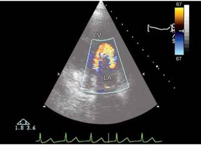
Fig. 9.4 : Circumferential flow around the ball in Starr-Edwards ball-in-cage prosthesis in mitral position. Transthoracic echocardio- graphic four-chamber view.
(LV: Left ventricle; LA: Left atrium)
valve is essential (Figs 9.1 to 9.4). Ball-in-cage valve has a silicone ball housed in metallic cage (three metallic arches) that is attached to the base ring.
• During the forward flow phase, flow emerging from the valve forms a circumferential jet that separates from ball, hits wall of the flow chamber and then flows along.
• A region of high-velocity gradient, and thus of high shear stress, exists at the edge of forward flow jet and recirculation region.2,3
• During end flow phase, the ball moves back on the valve seat, but a small gap may form, thus permitting a mild regurgitation.
TILTING OR MONO-DISK VALVE
Mono-disk or tilting-disk prostheses have a single disk of pyrolite carbon housed in a titanium casing with the help of struts or hinges (Figs 9.5 to 9.11).
• In open position, the disk tilts to form a major orifice and another minor orifice for the blood to flow.4-6
• A large forward flow jet emanates from the major orifice, whereas a smaller jet of lesser velocity emanates from the minor orifice.
• ttese two jets of different velocity induce a recirculation in the wake of disk. A recirculating flow pattern forms in the sinus region.
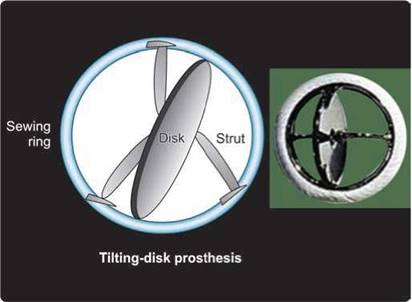
Fig. 9.5 : Mono-disk mechanical prosthesis. Mono-disk prosthesis has a single disk secured by lateral or central metal struts. The opening angle of the disk relative to the plane of valve annulus ranges from 60° to 80°, resulting in two distinct orifices of different sizes.
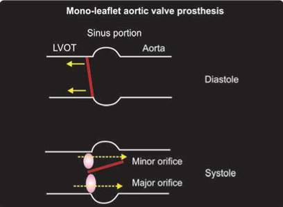
Fig. 9.6: Tilting mono-disk prosthesis in aortic position. There are two eccentric orifices for forward flow. Angle of disk opening depends upon the design. The disk totally occludes valve orifice in closed position and tilts to an angle in open position. The disk can rotate during normal function, thus preventing excessive contact wear from the retaining strut components on a particular region.
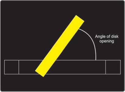
Fig. 9.7: Graphic representation of the mono-disk valve. Performance index is dependent upon the opening angle, which can be gauged by cine-fluoroscopy as well as by echocardiography.
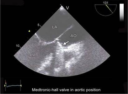
Fig. 9.8: Transesophageal long-axis view. Tilting-disk prosthesis in aortic position in diastole (arrow).
(AO: Aorta)
• During the closed phase, the tilting disk moves back and seats on the valve housing to occlude the valve orifice; however, a small gap may be present at the periphery of disk, thus permitting a small amount of flow regurgitation
Bileaflet design consists of two semicircular disks which pivot on hinges. Bileaflet valves have the best central flow—the leaflets open completely, allowing very little resistance to blood flow (Figs 9.12 to 9.18).45
• Open leaflets divide the area available for flow into three regions: two lateral orifices and a central orifice.7
• the major part of forward flow emerges from two lateral orifices.7
• High turbulent shear stress is present at locations of high velocity gradients and at locations immediately distal to the valve leaflets.
• the design of bileaflet mechanical heart valves includes some degree of leakage flow.
• During the leakage flow phase, the leaflets rotate to occlude the valve orifice.
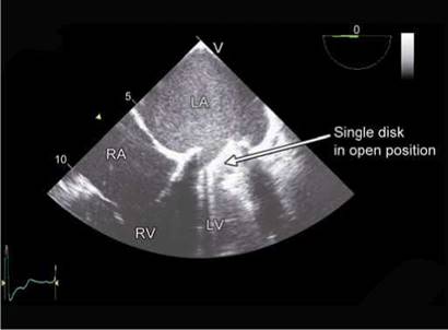
Fig. 9.9: Transesophageal echocardiographic four-chamber view showing an open tilting disk in mitral position. Note the angle of opening. (RA: Right atrium; RV: Right ventricle).

Fig. 9.10: Three-dimensional transesophageal view from the top in a patient with mono-disk Medtronic-Hall valve in mitral position. Arrows point to the sewing ring. Note single disk with two orifices.

Fig. 9.11: Medtronic-Hall valve #23 ( mono-disk prosthesis ) in mitral position in an apical view. Forward flow through major orifice (longer arrow) and minor orifice (shorter arrow). Recirculation zone is seen lateral to the major orifice.
bioprosthesis
The leaflet components of the bioprosthetic valves are composed of animal pericardium or animal valvar tissue. There is a substantial use of these valves in the elderly population and in females of childbearing age (Figs 9.19 to 9.24).
• Bioprosthetic heart valves are composed of three leaflets that open to form a central orifice for the blood to flow through, thus closely resembling a native semilunar valve.8
• A jet-like flow emerges from open leaflets during the forward flow phase. The jet is characterized by vena contracta immediately downstream of the valve, followed by an expansion region.8,9
• The forward flow j et is surrounded by counter-rotating recirculation regions.
• During closed phase, the leaflets coapt to prevent regurgitation; however, leakage flow may emanate from centre of the valve if leaflets do not close properly.
• General flow characteristics of all bioprosthetic valves are the same, differences do exist on valve-to- valve basis because of subtle changes in valve design, such as the height of the valve, the material (porcine, pericardial etc.) and stent characteristics (stented vs stentless valves).
• Stentless valves have superior performance with the largest effective orifice area.10
• Pericardial stented valves are known to have larger effective orifice area than porcine bioprostheses.11
hemodynamic assessment of prosthetic valves
All prosthetic valves are inherently stenotic as well as regurgitant. A baseline postdischarge echocardiographic evaluation is a prerequisite for detecting any change during serial studies. The echocardiographic evaluation of a prosthetic valve requires knowledge of valve details, concommitant procedures performed, anticoagulation status, and so on. It is essential to study the prosthetic valve

Fig. 9.12: Bileaflet mechanical prosthesis. Bileaflet valves are made of two semilunar disks attached to a rigid valve ring by small hinges. The opening angle of the leaflets relative to the annulus plane ranges from 75° to 90°, and the open valve has three orifices: a small, slit-like central orifice between the open leaflets and two larger semicircular orifices laterally.

Fig. 9.13: Note a central small orifice and two lateral orifices. Within the annular housing, each leaflet has an extension region, known as leaflet ear, which pivots about a recessed or protruding hinge.
(LVOT: Left ventricular outflow tract)

Fig. 9.14: Transesophageal echocardiographic four-chamber view showing bileaflet mitral prosthesis in diastole. Arrows point to two open disks with three orifices.

Fig. 9.15: Same as in Figure 9.14 except that bileaflet valve is seen in closed position.
structural details with its hemodynamic performance along with the functioning of the receiving chambers.
Normal transprosthetic regurgitation is seen as small two to three jets originating from the prosthesis and extending 1-1.5 cm into the receiving chamber (Figs 9.25 and 9.26). Regurgitation is of significance if color flow mapping shows transprosthetic jets of sufficient vena contracta (3 mm or more) or if the jet(s) originate from the side of the prosthetic ring.
Hemodynamic evaluation includes measurement of transprosthetic pressure gradients, flow and effective orifice area. Effective orifice area (EOA) of a prosthesis is of critical significance. the EOA is a physiological parameter that represents the minimal cross-sectional area of the transprosthetic blood flow jet, and is easily measured by Doppler echocardiography. Pressure gradient and effective orifice area are correlated with total energy loss and can be estimated noninvasively.

Figs 9.16A and B: Doppler color flow map showing three forward flow jets across the bileaflet mitral prosthesis in diastole. Left panel is a transesophageal image while the right panel shows transthoracic image.

Fig. 9.17: Three-dimensional transesophageal image of bileaflet St Jude #27 mitral prosthesis in open position. Line in the upper part of the image represents stitch artifact.

Fig. 9.18: Three-dimensional transesophageal echocardiographic en-face view from the top of the bileaflet mitral prosthesis in closed position.
Internal geometric area of a prosthesis is another anatomical parameter calculated from the static measurement of the internal diameter of the prosthesis. Geometric area measurement varies from one type of prosthesis to the other, while the ratio between the EOA and the geometric area also varies widely from one type and/or size of prosthesis to another.
As blood flows through the prosthetic heart valve, a sudden pressure drop occurs across the valve due to reduction in cross-sectional area within the valve housing. This can be quantified through the continuity equation and Bernoulli's equation (Fig. 9.27).
• ttere is a variable pressure drop across prosthetic valve depending upon the size, design and orientation of the prosthesis and the body size of the patient. A good performance is assured if the indexed aortic prosthetic valve area exceeds 0.85 cm2/m2 and the mitral prosthetic valve area is > 1.3 cm2/m2 (Fig. 9.28). Estimated prosthetic valve areas below this threshold can either be due to prosthetic valve stenosis or patient- prosthesis mismatch.
• Higher pressure drop causes higher shear stress and flow separation adjacent to the valve and pre-disposes to thrombus formation.
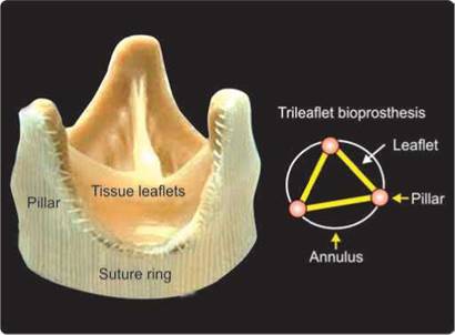
Fig. 9.19: Diagram of bioprosthesis with three leaflets like a natural semilunar valve supported by three flexible pillars.
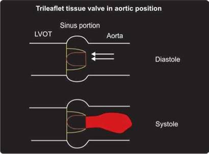
Fig. 9.20: Diagram depicts flow pattern (single central flow jet) across a trileaflet tissue valve in aortic position.
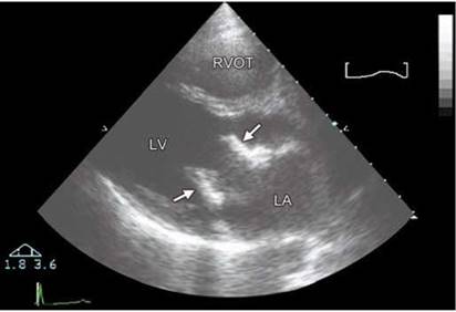
Fig. 9.21: Parasternal long-axis view. #27 Carpentier-Edwards bioprosthesis in diastole at mitral position. Arrows point to flexible pillars. Leaflets are thin and hardly visible.

Fig. 9.22: Transthoracic short-axis view showing mitral Carpentier- Edwards bioprosthesis in closed position. Note three pillars (P) and three leaflets (L).
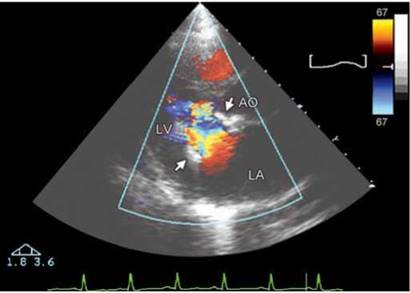
Fig. 9.23: Single central jet of forward flow in diastole. #27 Carpentier- Edwards bioprosthesis (Fig. 9.16).

Fig. 9.24: Transesophageal echocardiographic four-chamber view showing leaflets of a mitral bioprosthesis in open position. Note the leaflets are thin.

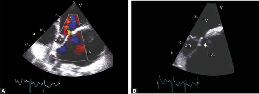
Figs 9.25A and B: #23 Medtronic-Hall valve in aortic position imaged in apical three-chamber view. There are two small jets of transprosthetic regurgitation in early diastole (closure backflow) and holodiastolic (leakage backflow).
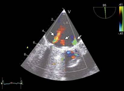
Fig. 9.26: Transesophageal image of a bileaflet mitral prosthesis in systole showing three physiological regurgitant jets.

Fig. 9.27: Diagram illustrating pressure drop across a prosthesis. Beyond the prosthesis, pressure drop decreases (pressure recovery). Pressure recovery varies depending upon the design of the valve.
• Effective orifice area is a metric of impedance to flow through the valve. A higher orifice area means less energy loss.
• Performance index is the effective orifice area divided by the size of the valve. It is reciprocal of flow impedance. Bileaflet valves typically have higher performance index than tilted-disk valves, which in turn have higher index than caged-ball valves.12-15
• Doppler gradients should be calculated based on side orifice velocity measurements or the Doppler gradient estimation should include the pressure loss coefficient when based on central orifice velocities (Fig. 9.29).
• Application of the simplified Bernoulli's equation to Doppler velocity measurements across the central orifices of St Jude valves will yield significantly higher calculated pressure gradients across the valve than the pressure gradient measured during cardiac catheterization ( Fig. 9.30).
• Pressure recovery is the variable increase in lateral pressure downstream from a stenotic orifice.
• An early peaking Doppler velocity profile of the aortic prosthesis would suggest either a pressure recovery phenomenon or increased flow across an unobstructed valve. Increased E velocity across mitral prosthesis

Fig. 9.28: Relationship of mean transprosthetic valve gradients with indexed effective orifice area at rest. There is an exponential increase in pressure gradients beyond a certain threshold of valve area.

Fig. 9.29: Graph illustrating pressure drop across a bileaflet prosthetic valve. Through the central small orifice, there is a greater pressure drop and greater pressure recovery downstream. Continuous wave Doppler interrogation of the central orifice will result in higher transprosthetic pressure gradients and smaller calculated effective orifice area.

Figs 9.30A and B: Continuous wave (CW) interrogation of a normally functioning bileaflet valve in mitral position. (A) Figure shows velocity profile across a central orifice (peak velocity 185 cm/sec with a peak gradient of 14 mm Hg). (B) Figure shows velocity profile across lateral orifice (peak velocity 149 cm/sec with a peak gradient of 9 mm Hg).
can occur in tachycardia, high output states, small prosthetic size, stenosis or regurgitation and caged-ball valves or central orifice of a bileaflet valve (Fig. 9.31).
• Pressure recovery is responsible for 50% or more of the Doppler gradients for almost all conditions (Fig. 9.31).
• Incorporation of the experimentally determined pressure loss coefficient for a bileaflet valve in the simplified Bernoulli's equation is necessary for a comparison of noninvasive Doppler gradients with the invasive gradients measured during cardiac catheterization.
Pressure loss coefficient is similar for all valve sizes. When the Doppler gradient (1/2pv2) across the central orifice is multiplied by the pressure loss coefficient K = 0.64, an excellent agreement is observed between the noninvasive and invasive transvalvular pressure gradients in patients with St Jude prosthesis.14 Occasionally, high transprosthetic pressure gradients are observed in patients who have eccentric orifice resulting into jet convergence on adjacent walls of the receiving chamber or vessel. This is because the jet converges twice before finally diverging (Figs 9.32 and 9.33).


Figs 9.32A and B: Normally functioning Medtronic-Hall tilting-disk prosthesis at aortic position in a 25-year old young man. Eccentric orifice results in high transprosthetic pressure gradients (peak pressure gradient 77 mm Hg, mean 41 mm Hg). Triangular shape of the Doppler spectrum suggests nonobstructed valve.

Fig. 9.33: Graphic illustration of greater pressure drop in a prosthesis with eccentric opening. Convergence-1 occurs at the prosthetic valve while convergence-2 at the level of posterior aortic wall as the jet redirects itself into the central lumen of the aorta.
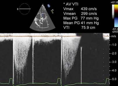
Fig. 9.34: Continuous wave Doppler spectrum of a normally functioning aortic prosthesis. Despite a high peak velocity (4.39 m/s), There is a rapid acceleration, triangular shape of the spectrum with early systolic peak. Note the second Doppler flow velocity spectrum between opening and closure artefacts.

Fig. 9.35: Intermittent transprosthetic mitral regurgitation. There is no regurgitation in first two cardiac cycles while the last three show it.
• If prosthetic valve dysfunction is suspected, careful examination of leaflet excursion by transthoracic or transesophageal imaging is necessary. When abnormal leaflet excursion is present (or suspected):
- the Doppler gradients across the central orifice should be calculated without incorporating the pressure loss coefficient into the simplified Bernoulli equation and/or
- the Doppler gradients should be measured across the side orifices, where pressure recovery is minimal and the simplified Bernoulli's equation is adequate.
• A transesophageal examination (2D or 3D) is mandatory whenever abnormally high transprosthetic pressure gradients are observed. High transprosthetic pressure gradients can occur with or without prosthetic valve dysfunction.
• The contour of the flow velocity through the prosthesis is a valuable index of prosthetic valve function in aortic position that is used in conjunction with the other quantitative indices.16 In a normally functioning prosthetic valve, even during high flow, there is a triangular shape of the continuous wave (CW) Doppler spectrum, with early peaking of the velocity and a short acceleration time (Fig. 9.34).16 Ratio of acceleration time to ejection time has been used in aortic prosthetic valves to decipher the significance of high gradients. A ratio of > 0.4 indicates prosthetic aortic valve obstruction.4
• With prosthetic aortic valve obstruction, the flow velocity contour is rounded with midsystolic peaking and slow acceleration.
• There may be intermittent obstruction occasionally and hence prolonged and careful examination may be necessary (Fig. 9.35).
technical considerations
A prior knowledge of the type and size of prosthesis is
essential. Size of the prosthesis denotes outer diameter
of the suture ring in mm. Body surface area should be

Fig. 9.36: Transthoracic echocardiographic off-axis view of the ventricles showing a bileaflet valve in mitral position. Angulating the probe to the right while imaging in short axis provides details of the mitral prosthesis.
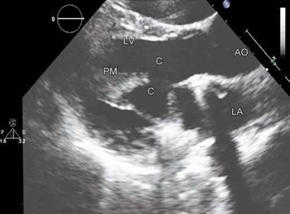
Fig. 9.37: Transthoracic echocardiographic parasternal long-axis view shows native chords (c) preserved and tucked behind the sewing ring of a mitral bileaflet valve. Papillary muscle (PM) is shown.
recorded to detect patient-prosthesis mismatch. Heart rate variation will cause change in transprosthetic gradients and hence should always be recorded and mentioned along with the pressure gradients.
• Transthoracic echocardiographic (TTE) examination is often tedious because of acoustic shadowing produced by the prosthesis and surgically altered rib cage.
• Transthoracic echocardiography requires multiple angulations and use of off-axis views (Fig. 9.36).
• Transesophageal echocardiographic (TEE) examination is more often needed for evaluation of prosthetic valves. 3D TEE is a valuable tool to detect cause of prosthetic valve obstruction.
• A complete examination of the chambers, other valves and functional quantification is required in every case.
• In case of aortic prosthesis, measurement of aorta at different locations is vital. Aortic root tends to dilate and there is propensity for dissection after replacement of a bicuspid aortic valve.
• Prosthetic valve components need to be imaged and examined carefully.
the opening and closing motion of the moving parts of the prosthesis (leaflets for bioprosthesis and disks/ ball for mechanical prostheses should be recorded and semiquantified.
• Presence or absence of leaflet calcifications or abnormal echo density attached to the sewing ring, occluder, leaflets, stents or cage and so on should be recorded.
• Appearance and motion of the sewing ring should be studied. Any separation from the native annulus and abnormal rocking motion should be carefully excluded.
• Increased mobility of the mitral prosthesis may be observed in those with preserved native leaflets and chordae. These should be differentiated from any abnormality (Fig. 9.37).
• Presence or absence and number of microbubbles upstream of transprosthetic flow should be documented.17,18
• Aortic root may be thickened after insertion of a stentless valve due to edema and hematoma.19 This may take 3-6 months to resolve (Fig. 9.38).
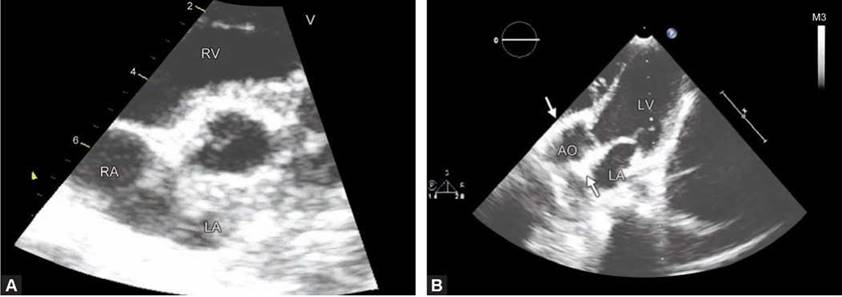
• In patients with or without suspicion of infective endocarditis, a search for the presence of abscess formation in the region of the prosthetic valve annulus or sewing ring should be undertaken (Fig. 9.39).
• Prosthetic dehiscence should be looked for diligently. Prosthesis dehiscence can cause paraprosthetic regurgitation (Fig. 9.40) or occasionally subannular pseudoaneurysms (Fig. 9.41).
• For hemodynamic evaluation of prosthetic valves, proximal and distal velocities should be recorded as in native valves. Effective orifice area should be estimated by the continuity equation using measured outflow tract diameter and not that provided by the manufacturer. A peak velocity > 2 m/s across a mitral prosthesis should be considered abnormal and a transaortic peak velocity > 4 m/s should be viewed with suspicion.
Figs 9.38A and B: Immediate postoperative stentless prosthesis in aortic position in diastole. Note the thickening of the aortic root (arrows) due to edema and hematoma. This tends to disappear over time.
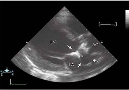
Fig. 9.39: Transthoracic echocardiographic parasternal long-axis view in a patient with aortic mechanical prosthesis and clinical diagnosis of infective endocarditis. Abscess (A) surrounded by arrows is depicted.
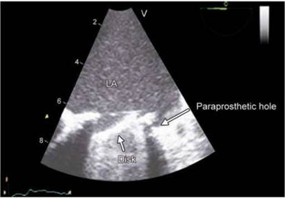
Fig. 9.40: Transesophageal echocardiographic image showing paraprosthetic hole marked by an arrow ( dehiscence) in a patient with tilting disk prosthesis in mitral position.
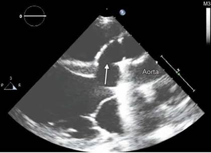
Fig. 9.41: Transthoracic echocardiographic parasternal long-axis view in a patient with aortic mechanical prosthesis. Arrow points to the subannular pseudoaneurysm extending anterior to the aortic root.
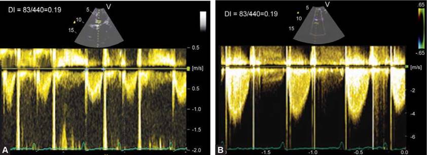
Figs 9.42A and B: Measurement of dimensionless index (DI) for a tilting-disc aortic prosthesis. A DI of 0.19 indicates prosthetic valve obstruction.

Figs 9.43A and B: Continuous wave (CW) Doppler interrogation of a mechanical mitral prosthesis. (A) Pressure-half time is 154 msec with pressure half-time derived mitral valve area of 1.43 cm2 (Left panel). (B) Figure shows valve area of 0.64 cm2 by continuity equation as stroke volume was 36 mL and mitral VTI 56.7 cm.
In these situations, further examination including TEE and cinefluoroscopy become essential. Similarly, a mean gradient of > 10 mm Hg across a mitral prosthesis should be considered abnormal.
• Dimensionless velocity index (DI) is an easilyobtainable parameter of aortic prosthetic valve function. It is the ratio of left ventricular outflow tract velocity to peak transprosthetic velocity. DI of > 0.30-0.35 indicates normal function, especially if associated with a short acceleration time of < 100 msec. DI of < 0.25 should be viewed with suspicion (Fig. 9.42). Dimensionless velocity index has also been suggested for mitral prosthesis (normal > 0.45) but is rarely used clinically.
• Pressure half-time measurement is frequently used in evaluating mitral and tricuspid valve prostheses. There is no validation for its use and mostly, valve area is overestimated unless there is moderate to severe valve stenosis. However, a pressure-half time exceeding 150 msec should be viewed with suspicion (Figs 9.43A and B) and prosthetic valve stenosis is likely if it exceeds > 200 msec.20
• In presence of atrial fibrillation, Doppler data from 5 to 15 cardiac cycles should be averaged. A sweep speed of 100 mm/sec is essential for Doppler measurements.
• Stentless valves are more likely to have minor regurgitation than stented biological valves (Fig. 9.44). Sometimes, these leaks are more than minor.
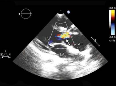
Fig. 9.44: Transthoracic echocardiographic parasternal long-axis view showing aortic regurgitation (arrow) in a stentless prosthesis.
(LV: Left ventricle; AO: Aorta; LA: Left atrium).

Fig. 9.45: Parasternal long-axis view in a patient with bileaflet valve in mitral position. Arrow points toward the microbubbles upstream of the valve in diastole.

Fig. 9.46: Transesophageal echocardiographic four-chamber view showing flail leaflet (arZrow) of a mitral bioprosthesis.
(LA: Left atrium; LV: Left ventricle).
microbubble formation (cavitation)
It is not uncommon to see microbubbles upstream of the prosthetic valves. Microbubbles form due to shear stress in the vena contracta and implode in divergence cone where pressure recovery occurs (Fig. 9.45).
• Cavitation is suspected as a contributing factor in blood cell damage and increased risk of thromboembloic complications.
• Collapse of the microbubbles can cause pressure or thermal shockwaves and blood microjets that can damage a surface.

• More microbubbles are seen in conditions that increase contractility.
• A few microbubbles may not be of much consequence.17,18
Prosthetic valve are prone to wear and tear, mechanical failure, thrombosis, infection and host tissue reaction. Table 9.2 lists the prosthetic valve dysfunctions.
In bioprosthetic degeneration, the leaflets get thickened, flail, torn or calcified with or without fusion of the commissures (Figs 9.46 and 9.47).21-24 Degenerative calcification results in stenosis and regurgitation of the valve. Not all bioprostheses showing structural valve

Fig. 9.47: Transthoracic echocardiographic four-chamber view showing structural degeneration of the mitral bioprosthesis (arrow).
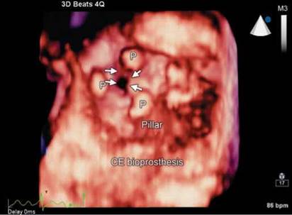
Fig. 9.48: 3D Transesophageal echocardiographic view from the top in a patient with Carpentier-Edwards (CE) Bioprosthesis in mitral position showing stenosis (arrows) of the orifice in diastole.
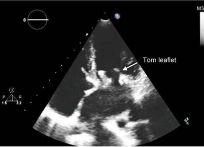
Fig. 9.49: Transthoracic echocardiographic (TTE) four-chamber view showing torn leaflet of a mitral bioprosthesis.

Fig. 9.50: 3D Transesophageal echocardiographic view from the top of a mitral bioprosthesis in diastole. There is segmentation of the orifice due to torn leaflets (arrows).
(P: Pillar; STL: Septal tricuspid leaflet; ATL: Interior tricuspid leaflet; PTL: Posterior tricuspid leaflet).
degeneration suffer from stenosis and calcification (Fig. 9.48). Some valves show only rupture of the cusps (Fig. 9.49) whereas others show the combination of leaflet calcification and rupture.
Tears in the leaflets are associated with microscopic or macroscopic calcification of the tissue.21-24 For stentless porcine aortic valves, the mode of failure leading to reoperation is predominantly cusp rupture, inducing sudden regurgitation. Flail and torn leaflets tend to segment the orifice (Fig. 9.50).
Following points are worth mentioning in regard to structural degeneration:
• It usually occurs 7-8 years after implantation.
• More common with porcine than bovine pericardium.
• More often in mitral position.
• More often in younger patients.
• More often in older generation of bioprostheses.
prosthetic and paraprosthetic regurgitation
Mechanical prostheses have a normal regurgitant volume known as leakage backflow. ttis physiological regurgitation prevents blood stasis and thrombus formation using a
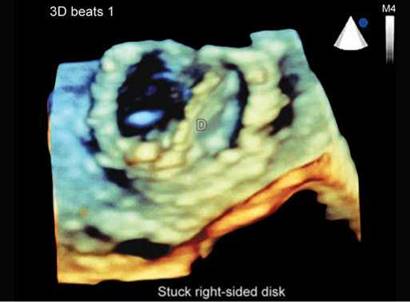
Fig. 9.51: 3D Transesophageal echocardiographic view from the top of a mitral prosthesis in diastole. Disk on the left side is completely open and the one on the right side is stuck in partially open position. Partially opened fixed disk causes transprosthetic mitral regurgitation.
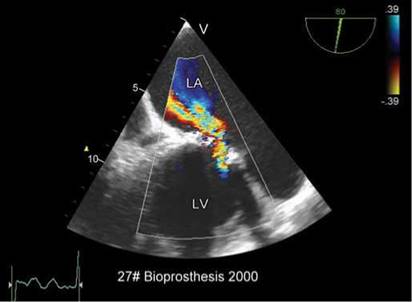
Fig. 9.52: 2D Transesophageal echocardiographic view showing severe transprosthetic regurgitation across a mitral bioprosthesis. Note large proximal flow acceleration.

Figs 9.53A and B: Transesophageal echocardiographic images of a mitral bioprosthesis in a young female. The leaflets are thin but there is a tear (arrow) with severe mitral regurgitation (right panel).
washing effect.25 As opposed to the pathological regurgitant jets, the physiological regurgitation jets are characterized by being short in duration, narrow and symmetrical. Abnormal prosthetic regurgitation can occur due to:
• Mechanical failure of the prosthesis (Fig. 9.51).
• Degeneration of a bioprosthesis (Fig. 9.52).
• Interference by an abnormal structure like thrombus, vegetation or remnants of the native valve.
• Leaflet tear (Fig. 9.53).26
Severity of transprosthetic mitral regurgitation is judged by parameters similar to those applied to the native valves although not well validated. Prominent
proximal flow acceleration (Fig. 9.52) and a peak E mitral velocity > 2.5 m/s (Fig. 9.54) strongly suggests severe mitral regurgitation. Other indirect clues are enlarged left ventricle and significant pulmonary hypertension.
paraprosthetic regurgitation
Paraprosthetic regurgitation occurs due to dehiscence of the sewing ring either because of degenerative structural changes of the surrounding tissue, suture giving away, calcification of the native annulus or due to infective endocarditis. Large paraprosthetic leaks tend to cause

Fig. 9.54: Degenerated Carpentier-Edwards mitral bioprosthesis showing severe transprosthetic mitral regurgitation by continuous wave (CW) Doppler interrogation. Note Peak E velocity exceeding 3 m/s (pressure half-time is 150 msec) with dense systolic regurgitant jet signals.
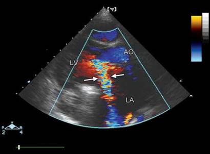
Fig. 9.55: Transthoracic echocardiographic (TTE) parasternal long-axis view showing eccentric paraprosthetic mitral regurgitation (arrows). Marked proximal flow acceleration is seen.
(AO: Aorta; LV: Left ventricle; LA: Left atrium)
Figs 9.56A and B: Small paraprosthetic mitral regurgitation with clear delineation of the dehiscence (arrow). (LV: Left ventricle; AO: Aorta; LA: Left atrium).
rocking of the prosthesis. The assessment of severity is similar to that of native valves with minor differences. A regurgitant orifice area > 0.5 cm2 is considered to represent severe mitral regurgitation. Similar values are not reported for paraprosthetic aortic regurgitation. However, acoustic shadowing during THE may create difficulty in assessing presence and severity of regurgitation and multiple off-axis views may be needed to discover regurgitation jet. Transesophageal echocardiography is of immense value and should be routinely used when paraprosthetic regurgitation is suspected (Figs 9.55 to 9.59).
prosthetic valve stenosis
The presence of increased transprosthetic gradient (mean gradient > 15-20 mm Hg for aortic prostheses and > 5-7 mm Hg for mitral prostheses) at rest with normal range of heart rates is not uncommon in normally functioning prostheses and may not be equated with intrinsic prosthesis dysfunction. A high gradient can be due to an associated subvalvular obstruction or a hyperkinetic circulatory state or valvular regurgitation. Such occurrences can be suspected when the dimensionless index is normal. Distinction must be made between obstruction

Figs 9.57A and B: Transesophageal echocardiographic examination of ball-in-cage valve in mitral position. Note two jets of paraprosthetic regurgitation with bigger jet on the lateral side (arrow).

Fig. 9.58: Transesophageal echocardiographic long-axis view showing eccentric paraprosthetic aortic regurgitation (arrow) in a patient with tilting-disk implantation. Vena contracta width of 9 mm suggests severe regurgitation.

Fig. 9.59: Dehiscence of a Starr-Edwards mitral prosthesis (arrow)
resulting from patient-prosthesis mismatch, which is by far the most frequent cause of high pressure gradients (present right from the immediate postoperative phase), and intrinsic prosthesis dysfunction, which is a pathological condition requiring immediate attention.27
If the calculated EOA is below the reference value and if the prosthesis is not a bileaflet mechanical valve, prosthesis valve dysfunction should be considered, and confirmation should be sought with TEE, and cinefluoroscopy. Incidence of prosthetic valve obstruction can be as high as 4% per year.4
Main causes of prosthetic valve stenosis are:
• Pannus formation (Figs 9.60 to 9.65).
• ttrombosis (Figs 9.66 to 9.68).
• Pannus + ttrombosis (Fig. 9.69).
• Structural degeneration of the bioprosthesis (Figs 9.70 and 9.71).
• Ball variance due to lipid absorption (Figs 9.72 and 9.73).
• Mechanical failure (Fig. 9.74).
Pannus is a membrane of granulation tissue in response to healing. Pannus grows in the tissue valve interface usually. It tracks and creeps along the suture lines. This does not encroach the valve orifice or chamber space generally, but the hanging edges can hit upon a leaflet occasionally. This is more common with tilting disk

Fig. 9.60: Transesophageal echocardiographic four-chamber view in a 29-year old female with #27 Omniscence tilting disk valve. Arrow points to the pannus.

Fig. 9.61: 2D Transesophageal echocardiographic view shows arrested lateral disk of a bileaflet valve. Red arrows point to the pannus.
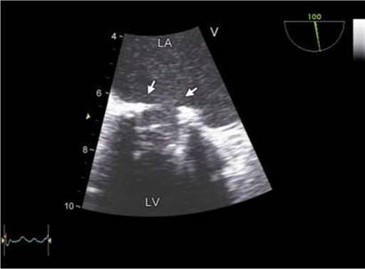
Fig. 9.62: 2D Transesophageal echocardiographic view of a Starr- Edwards mitral prosthesis. Arrows point to the circumferential pannus reducing the internal diameter of the sewing ring.

Fig. 9.63: 3D Transesophageal echocardiographic view from the top of a bileaflet mitral valve showing circumferential nodular pannus (arrows).
on the side of minor orifice. When excessive it can make a valve leaflet almost standstill. Pannus overgrowth narrows circumferentially the inflow and outflow aspects of the prosthesis by extending into both atrial and ventricular sides. The incidence of pannus formation in prosthetic heart valves in the aortic position is described as between
0.1% and 0.6% per patient per year.4,27
There is a significant overlap between echocardio- graphic appearance of a pannus and a thrombus. Thrombus tends to have echogenic texture similar to myocardium and is not as echo-dense as a pannus is. It is usually more localized, more mobile and tends to
obstruct orifice. Compared to pannus formation, thrombi are usually larger and, in the case of mitral prostheses, extended more often into the left atrium. There is a clinical need to define a thrombus and its location. The different therapeutic modalities available for valve thrombosis (heparin treatment, fibrinolysis, surgery) are influenced by the presence of valvular obstruction, by valve location (left- or right-sided), and by clinical status. Biological valves rarely get thrombosed. Thrombus formation on a mechanical valve is more common than is clinically recognized. Routine TEE in postoperative period shows about 10% patients with some degree of thrombus

Fig. 9.64: 3D Transesophageal echocardiographic view from the top of a tilting-disk mitral prosthesis. Arrows point to pannus formation with impingement upon the orifice. Note that no suture loops are visible due to tissue growth.

Fig. 9.65: 3D Transesophageal echocardiographic view from the top showing pannus (arrows) in a patient with tilting disk aortic valve prosthesis.
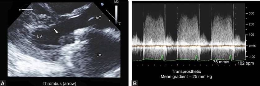
Figs 9.66A and B: (A) Transthoracic echocardiographic parasternal long-axis view showing thrombus (arrow) between the two leaflets of a bileaflet valve.(B) Figure shows transprosthetic gradients.

Fig. 9.67: Transesophageal echocardiographic view of a bileaflet mitral valve showing a large thrombus (arrow T). Thrombus is obstructing the affected disk.
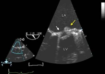
Fig. 9.68: Transesophageal echocardiographic four-chamber view showing a tilting- disk mitral valve with a thrombus (yellow arrow) and pannus ( white arrow).

Fig. 9.69: 2D Transesophageal echocardiographic view of a bileaflet mitral prosthesis. Arrows point to thrombi. Note a thrombus in left atrial appendage (right arrow).

Fig. 9.70: Transesophageal echocardiographic four-chamber view showing a very narrow flow jet across a mitral bioprosthesis due to structural degeneration.
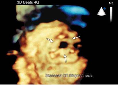
Fig. 9.71: 3D Transesophageal echocardiographic view of mitral bioprosthesis of the same patient as in Figure 9.70. Note the orifice narrowing and thickening and fusion of the three leaflets.
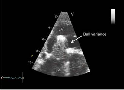
Fig. 9.72: Starr-Edwards ball-in-cage valve showing ball variance due to lipid absorption.
formation. In a study by Deviri et al.27 evaluating the surgical findings of 112 obstructed mechanical valves, pannus formation was the underlying cause in 10.7% of valves, pannus in combination with thrombus was present in 11.6%, whereas thrombus alone or with little pannus formation was found in 77.7%.
Inadequate anticoagulation not only can predispose to valve thrombosis but also thrombus formation elsewhere like in left atrial appendage (Fig. 9.69).
Ball variances observed in ball-in-cage prosthesis include increase or decrease in size, deformation or
lobulation, changes in color and considerable softness (Fig. 9.65). The loss of random motion of the ball due to pathway impingement leads to more injury to the cage. Increased velocity of blood flow across the ball due to leakage or obstruction drives lipids into the ball making it more swollen up and still greater obstruction.28
The intermittent or permanent mechanical dysfunction causing jamming of the leaflet(s) may be a result of dynamic or fixed distortion of the pivot guards during the cardiac cycle (Fig. 9.74).29 Disk fracture and embolization have been reported rarely.30 Patients with hypertrophy of

Fig. 9.73: 2D Transesophageal echocardiographic four-chamber view in a patient with Starr-Edwards mitral prosthesis. Note the pannus (white arrows) causing severe narrowing of the annulus along with ball variance (multiple horizontal lines, yellow arrow).
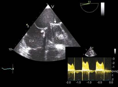
Fig. 9.74: Transesophageal echocardiographic four-chamber view showing an arrested disk (arrow) causing high transprosthetic gradients (inset). There is no evidence of a thrombus or pannus on the valve.

Fig. 9.75: Trileaflet bioprosthesis in pulmonary valve position in a case of operated tetralogy of Fallot.

Fig. 9.76: Continuous wave (CW) Doppler interrogation through a pulmonary valve bioprosthesis. Forward flow velocity is 2 m/s. Some regurgitation is noted.
the basal septum may be more susceptible to intermittent jamming of the aortic bileaflet valve and leaflet pivots due to distortion of the pivot guards.
tricuspid and pulmonary prosthetic valves
There is limited data with regard to tricuspid and pulmonary valve prostheses. Usual indications are in some patients with congenital heart disease, carcinoid valvular disease and rheumatic heart disease. In tricuspid valve disease, usually repair with annuloplasty is recommended
due to high chance of valve thrombosis or degeneration. However, mechanical or biological valves are also used. Normally functioning tricuspid prosthetic valves have a mean gradient < 5 mm Hg and pressure half-time < 150 msec. Transprosthetic regurgitation is assessed in a manner similar to that of mitral prosthesis.
In pulmonary valve position, usually bioprostheses (homografts or xenografts) are used when there is severe pulmonary regurgitation (Figs 9.75 and 9.76). Peak forward flow velocities > 3 m/s are considered abnormal. Pulmonary regurgitation can be assessed with similar parameters as used for aortic prosthetic valve
regurgitation although with limited validation. Some
degree of regurgitation is invariably recorded in pulmonary bioprostheses.
summary and key points
• Evaluation of prosthetic heart valves requires an integrated approach using history, intra- and postoperative data, clinical examination, echocardiography and cinefluoroscopy.
• A baseline echocardiogram with detailed evaluation is required to follow-up these patients. Serial studies are of use when an asymptomatic abnormality is suspected.
• Reliance on pressure gradients or EOA alone may be fallacious because prosthetic valves have peculiar hemodynamics.
• Structural details are best seen by TEE. 3D TEE has emerged a powerful tool for structural evaluation.
• Patient-prosthesis mismatch needs to be noted immediately after the operation.
• Chamber reverse remodeling or lack of it is to be noted besides prosthetic valve evaluation in each patient.
• Catheter-based procedures to treat paraprosthetic regurgitation, degenerative aortic valve stenosis and biological valve stenosis are multiplying. This requires a greater integration of several imaging modalities with echocardiography.
• Although stress echocardiography has been used for evaluation of prosthetic valves, validation studies are lacking.
references
1. Yoganathan AP, Chandran KB, Sotiropoulos F. Flow in prosthetic heart valves: state-of-the-art and future directions. Ann Biomed Eng. 2005;33(12):1689-94.
2. Yoganathan AP, He Z, Casey Jones S. Fluid mechanics of heart valves. Annu Rev Biomed Eng. 2004;6:331-62.
3. Dasi LP, Sucosky P, de Zelicourt D, et al. Advances in cardiovascular fluid mechanics: bench to bedside. Ann N Y Acad Sci. 2009;1161:1-25.
4. Zoghbi WA, Chambers JB, Dumesnil JG, et al. Recommendations for evaluation of prosthetic valves with echocardiography and Doppler ultrasound: a report From the American Society of Echocardiography's Guidelines and Standards Committee and the Task Force on Prosthetic Valves, developed in conjunction with the American College of Cardiology Cardiovascular Imaging Committee, Cardiac Imaging Committee of the American Heart Association, the European Association of Echocardiography, a registered branch of the European Society of Cardiology, the Japanese
Society of Echocardiography and the Canadian Society of Echocardiography, endorsed by the American College of Cardiology Foundation, American Heart Association, European Association of Echocardiography, a registered branch of the European Society of Cardiology, the Japanese Society of Echocardiography, and Canadian Society of Echocardiography. J Am Soc Echocardiogr. 2009; 22(9):975-1014.
5. Zoghbi WA. New recommendations for evaluation of prosthetic valves with echocardiography and Doppler ultrasound. Methodist Debakey Cardiovasc J. 2010;6(1): 20-6.
6. Lindower PD, Dellsperger KC, Johnson B, et al. Variability of regurgitation in Bjork-Shiley mitral valves and relationship to disc occluder design: an in vitro two-dimensional color-Doppler flow mapping study. J Heart Valve Dis. 1996;5(Suppl 2):S178-83.
7. Jones M, Eidbo EE. Doppler color flow evaluation of prosthetic mitral valves: experimental epicardial studies. J Am Coll Cardiol. 1989;13(1):234-40.
8. Weintraub WS, Clements SD, Dorney ER, et al. Clinical, echocardiographic, continuous wave and color Doppler evaluation of bioprosthetic cardiac valves in place for more than ten years. Am J Cardiol. 1990;65(13):935-6.
9. Alam M, Rosman HS, Hautamaki K, et al. Color flow Doppler evaluation of cardiac bioprosthetic valves. Am J Cardiol. 1989;64(19):1389-92.
10. Mohammadi S, Tchana-Sato V Kalavrouziotis D, et al. Long-term clinical and echocardiographic follow-up of the Freestyle stentless aortic bioprosthesis. Circulation. 2012;126(11 Suppl 1):S198-204.
11. McCarthy FH, Bavaria JE, Pochettino A, et al. Comparing aortic root replacements: porcine bioroots versus pericardial versus mechanical composite roots: hemodynamic and ventricular remodeling at greater than one-year followup. Ann Thorac Surg. 2012;94(6):1975-82; discussion 1982.
12. Baumgartner H, Khan S, DeRobertis M, et al. Discrepancies between Doppler and catheter gradients in aortic prosthetic valves in vitro. A manifestation of localized gradients and pressure recovery. Circulation. 1990;82(4):1467-75.
13. Khan SS. Assessment of prosthetic valve hemodynamics by Doppler: lessons from in vitro studies of the St. Jude valve. J Heart Valve Dis. 1993;2(2):183-93.
14. Vandervoort PM, Greenberg NL, Powell KA, et al. Pressure recovery in bileaflet heart valve prostheses. Localized high velocities and gradients in central and side orifices with implications for Doppler-catheter gradient relation in aortic and mitral position. Circulation. 1995;92(12):3464-72.
15. Fisher J. Comparative study of the hydrodynamic function of six size 19 mm bileaflet heart valves. Eur J Cardiothorac Surg. 1995;9(12):692-5 discussion 695.
16. Ben Zekry S, Saad RM, Ozkan M, et al. Flow acceleration time and ratio of acceleration time to ejection time for prosthetic aortic valve function. JACC Cardiovasc Imaging. 2011;4(11):1161-70.
17. Glen SK, Wilson ES, Grosset DG. Transesophageal echocardiography microbubbles with prosthetic valves. Am Heart J. 1995;130(6):1312.
18. Orsinelli DA, Pasierski TJ, Pearson AC. Spontaneously appearing microbubbles associated with prosthetic cardiac valves detected by transesophageal echocardiography. Am Heart J. 1994;128(5):990-6.
19. Takami Y, Ina H. Resolution of perivalvular hematoma of the Freestyle stentless aortic root bioprosthesis implanted with a subcoronary technique. Jpn J Thorac Cardiovasc Surg. 2001;49(11):675-8.
20. Mohan JC, Agrawal R, Arora R, et al. Improved Doppler assessment of the Bjork-Shiley mitral prosthesis using the continuity equation. Int J Cardiol. 1994;43(3):321-6.
21. Iyer A, Malik P, Prabha R, et al. Early Postoperative Bioprosthetic valve calcification. Heart Lung Circ. 2013;22(10) 873-7.
22. Butany J, Feng T, Luk A, et al. Modes of failure in explanted mitroflow pericardial valves. Ann ttorac Surg. 2011; 92(5):1621-7.
23. Flameng W, Herregods MC, Vercalsteren M, et al. Prosthesis-patient mismatch predicts structural valve degeneration in bioprosthetic heart valves. Circulation. 2010;121(19): 2123-9.
24. Shetty R, Pibarot P, Audet A, et al. Lipid-mediated inflammation and degeneration of bioprosthetic heart valves. Eur J Clin Invest. 2009;39(6):471-80.
25. Nellessen U, Schnittger I, Appleton CP, et al. Transesophageal two-dimensional echocardiography and color Doppler flow velocity mapping in the evaluation of cardiac valve prostheses. Circulation. 1988;78(4):848-55.
26. Haziza F, Papouin G, Barratt-Boyes B, et al. Tears in bioprosthetic heart valve leaflets without calcific degeneration. J Heart Valve Dis. 1996;5(1):35-9.
27. Deviri E, Sareli P, Wisenbaugh T, et al. Obstruction of mechanical heart valve prostheses: clinical aspects and surgical management. J Am Coll Cardiol. 1991;17(3):646-50.
28. Collins JJ Jr, Berg EJ, Harken DE. Silicone ball variance. A clinical and pulse duplicator study. Ann ttorac Surg. 1968;6(6):546-51.
29. Grattan MT, ttulin LI. Leaflet arrest in St Jude Medical and CarboMedics valves: an experimental study. Eur J Cardio- thorac Surg. 2004;25(6):953-7.
30. Mosterd A, Shahin GM, van Boven WJ, et al. Images in cardiovascular medicine. Leaflet fracture of a St. Jude mechanical bileaflet valve. Circulation. 2005;111(18): e280-1.