Introduction
General comments
Achieving diagnostic quality radiographs whilst minimizing patient dose is the goal of any imaging department, and this is no more important than in paediatrics. Children are special cases, since they have a two to four times higher risk of late manifestations of the detrimental effects of radiation (UNSCEAR Report 2000).
Staff working with children need skill and experience in order to gain their patients’ confidence and cooperation. A clear commitment to paediatrics is essential and a dedicated core group of staff responsible for children and for advising others is vital. In this way there can be an understanding of a child’s needs, development, psychology and range of pathology.
Dedicated paediatric areas, rooms, equipment and staff all lead to a far higher likelihood of a high-quality examination, at an achievable low dose, without protracted investigation times and without causing undue stress to the child, parent or staff.
Legislation
An environment of quality and safety within diagnostic imaging departments has been progressively promoted and encouraged throughout the European Community over the last few years. The Commission of European Communities has provided support by establishing legal requirements for the radiation protection of the patient and it has been clearly recognized that particular emphasis must be placed on paediatrics. The key to the optimization of paediatric imaging is to produce a radiograph which is of sufficient quality for a radiological diagnosis, at the lowest achievable dose. The need for specific recommendations with regard to objectively defining quality led to the publication of European Guidelines on Quality Criteria for Diagnostic Radiographic Images in Paediatrics in 1996. The guidelines contain image quality criteria and entrance surface doses for a standard 5-year-old child, with examples of good technique which would allow these criteria to be met. The criteria given in this chapter are based on the recommendations of the European text but are separated into two categories so that problems due to technique can be differentiated from those arising from varying physical parameters (e.g. kVp, grid).
National Reference Doses are produced and published by the National Radiological Protection Board (NRPB). These are based on rounded 3rd quartile values of a national survey and are reviewed every five years (IPEM Report 2004). In children it is not possible to produce meaningful reference doses without considering their varying size. The NRPB have addressed this by providing normalization factors which can be applied to reference doses for five standard sizes (O, — 1, — 5, —10 and 15 years) (Hart et al. 2000).
The Ionising Radiations (Medical Exposure) Regulations (IRMER) 2000 require the establishment of local diagnostic reference levels derived from local dose audit in addition to National Reference Doses. The Ionising Radiation Regulations emphasize responsibilities for all professionals involved in the use of ionizing radiation and stress the importance of justification, optimization and protection, which should be considered before undertaking a radiographic examination.
Justification
The dose reduction measures achieved by improving radiographic practice are insignificant compared with the doses saved from not performing the examination at all.
Justification is the essential first step in radiation protection, and it is the duty of all radiographers and radiologists to ensure that every investigation performed is the correct examination and is essential in the management of the patient. The Royal College of Radiologists’ (RCR 2003) handbook Making the Best Use of a Department of Clinical Radiology addresses the need for advice on justification and where at all possible recommendations are evidence based.
The RCR lists a simple series of questions that should always be answered before the investigation is undertaken:
• Is this investigation going to change the patient’s management?
• Does the investigation need to be done now?
• Has the investigation been done already?
• Has the appropriate clinical information been given to justify the request?
• Are too many investigations being requested simultaneously?
The guidelines also give advice regarding appropriate imaging pathways in paediatrics.
Referral criteria for 17 common paediatric investigations have also been described by Cook et al. (1998). The criteria include not only when investigations should be performed but also, importantly, when investigations should not be performed and when a more senior clinical referral is required. For example, an abdominal radiograph in non-specific abdominal pain is unlikely to demonstrate pathology in the absence of loin pain, haematuria, diarrhoea, a palpable mass, abdominal distension or suspected inflammatory bowel disease; a follow-up chest X-ray (CXR) is not required routinely for follow-up of simple pneumonia in a clinically well child; and some radiographs should not be performed routinely before there has been development of certain normal structures, e.g. sinuses, nasal bones, scaphoids. Where formal referral criteria are not given, reference should be made to the manual of Cook et al. (1998) and the RCR (2003) guidelines, which can be adapted to conform with local protocols and requirements.
Optimization
Once it has been decided that an investigation needs performing, choice of the most appropriate technique is essential. In view of the plethora of imaging techniques now available, radiologists and radiographers are best placed to give clinicians advice.


Optimization
However, due to the pressures on most departments, individual advice is not possible for every case, and agreed written guidelines between clinicians and X-ray staff should be compiled. Justification and optimization need good clinico-radiological cooperation.
Examples of optimization include the use of faster image acquisition systems such as screen/film systems for follow-up studies, using a lower kVp/higher mAs to optimize bony definition in non-accidental injury (NAI) CXR examination, and the use of additional lateral coning devices to protect the developing breast in follow-up studies of scoliosis in the adolescent female.
The patient
Child development
In the context of diagnostic imaging, childhood can be divided into six main age groups, each of which has different needs and capabilities:
• birth to six months;
• infancy (six months to three years);
• early childhood (three to six years);
• middle childhood (six to 12 years);
• early adolescence (12-15 years);
• late adolescence (15-19 years).
Each age group requires a different level of interaction, tolerance and understanding (Von Waldenburg Hilton and Edwards, 1994).
In the age group birth to six months, it is relatively easy to examine a child, as such children are not yet fearful of strangers. They sleep easily and can usually be quietened by a simple bottle-feed.
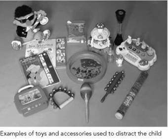
At six months to three years, children become increasingly fearful of strangers and cling to their parents. Communication with children of this age may be particularly difficult. Parents will usually have to maintain very close body contact with their child. The use of flashing or musical toys, blowing bubbles, simple rattles or bells may be useful in distracting children of this age. It may also be useful to allow some time for the child and their parents to become familiar with new surroundings before a procedure is undertaken.
At three to six years, communicating is easier but should be limited to simple, child-friendly terminology. Children of this age will often be more cooperative if there is an element of play involved, e.g. describing various pieces of equipment as space ships, seesaw rides, etc. They also have an awareness of modesty, and allowing them to leave on some of their normal clothes can be helpful. Projectors or videos showing exciting changing pictures on walls are also very useful. Children of this age are often extremely physically active and often do not respond well to attempts at physical restraint. If close parental involvement is not helpful, then swaddling young children in cotton blankets or towels can be useful for some examinations.
Children aged six to 12 years are of school age and have a growing capacity to understand what degree of cooperation is required of them and how the results of any tests will be helpful in treating their problems. An awareness of the most fashionable popular toys is very useful. It is also essential that any posters, books, games, etc. in the department are as up-to-date as possible to maintain credibility.
At 12-19 years, children become increasingly embarrassed and aware of their bodies and their development. It is essential at this age that communication and explanation should match their level of maturity. Their right to privacy must be respected at all times. This may include ensuring that there are areas of the department where confidentiality can be maintained, which may involve discussions without the parents being present if the adolescent so desires. If there is a male radiographer, it is advisable that a parent or carer accompanies a female child.
Anatomical differences between children and adults
Not only are children smaller, but their bodies are also different, e.g.:
• Young babies have thin skull vaults and vascular markings are not present before the age of one year.
• The nasal bones are not ossified before three years of age.
• Paranasal sinuses are not normally pneumatized until six years of age.
• The scaphoid bone is not ossified before six years of age.
• The smaller depth of the thorax (antero-posterior diameter) results in less enlargement of the heart, due to magnification, on antero-posterior projections of the chest compared with adults.
• The thymus contributes to the cardio-mediastinal shadow in young children and its variable presentations can mimic pathology.
• Multiple ossification centres at various sites can cause confusion, and reference texts (Keats and Anderson 2001) should always be available. This, in combination with high-quality images, will aid interpretation.
• Children have faster heart and respiratory rates than adults.
• More radiosensitive red bone marrow is more widespread in children and is present in almost all bones of a neonate.
These anatomical differences should be taken into account when optimizing techniques in paediatric radiography, e.g. it is obvious that specific scaphoid views are unnecessary in children under the age of six years.

Approach to a paediatric patient
One should always introduce oneself to a child and parent in a friendly and capable manner. The child’s name, age and address should be verified. It is important to speak to the child at their level. A firm but kindly approach is required, and the child should be escorted into the already prepared imaging room. It is preferable for the X-ray tube to be in the correct position. Adjusting its height over the child can be disconcerting. Usually only one parent is asked to accompany the child into the room. This complies with radiation protection guidelines. However, both parents are sometimes required for holding.
A very encouraging, reassuring attitude has to be adopted, and an enormous amount of praise should be given for every single act of cooperation, e.g. ‘You are the best child at keeping still we have had all day!’ and ‘You are so clever!’
Always be honest in answering any questions, as keeping one’s credibility is essential in maintaining rapport with children. Allow the child to see the effect of switching on the light beam diaphragm or riding on a chair or table beforehand if necessary.
Rewards of stickers, balloons and bravery certificates are a must. If a child’s first experience of an X-ray department is a pleasant one, then any future attendances will be far easier.
Given the right approach and surroundings, most children are cooperative. However, there are some who become physically aggressive and abusive, throwing temper tantrums at every suggestion. In these situations, it is better to get on with the procedure as quickly as possible; a firm approach and a range of simple, well-tried immobilization devices are recommended. Lots of cuddles with the parents/carer afterwards should soon calm the child.
Children attending as outpatients rarely need more preparation than the above for uncomplicated radiology. However, children over four years of age and having abdominal radiographs for suspected calculi/calcification or intravenous urography examination are given oral bowel preparation depending on bowel habits and age.

The patient
Children admitted as inpatients need more specific preparation, including liaising with the ward nursing staff and arranging a nurse escort where necessary. Planning of any radiograph should allow for the presence of any intravenous lines, drainage tubes, stomas, etc. It should be ascertained whether the patient will have adequate oxygen supply or intravenous fluid before arranging the examination.
If any patient has a contagious disease, then barrier methods of handling must be instituted. A decision should be made as to whether the patient should be brought to the department or whether the examination should be performed with mobile equipment. In addition, careful timing of the examination in order to avoid close proximity with other vulnerable patients is recommended (e.g. immunocompromised patients, neonates). Plastic aprons, gloves and careful hand-washing are required of all attendants. Masks or eyewear are necessary only if splattering of any body fluids is likely. All items contaminated by body fluids should be disposed of carefully according to local health and safety rules. All equipment that comes into contact with the child should be disinfected with the recommended cleaning agent for that equipment.
As in outpatients, other specific preparation for simple radiographs is rarely required. However, a prone invertogram (see page 401) for assessment of imperforate anus should not be performed in neonates less than 24 hours after birth, so as to allow more distal bowel to be delineated, and should be taken after the patient has been kept in the prone position for 15 minutes. In our experience, sedation has not been required for plain radiography. However, more lengthy procedures, which are beyond the scope of this book, may need sedation. Our preference is to use chloral hydrate (50mg/kg for scanning procedures). Complex procedures may require a short general anaesthetic. It is essential that all those involved in the sedation of children are well trained and updated in resuscitative techniques.

The patient
Pregnancy
This can be a difficult issue, but the guidelines of the RCR (2003) state that the possibility of pregnancy should be broached in all female patients who have started menstruating (approximately over the age of 12 years). Discretion is essential, and honest answers are more likely to be given if the child is not with her parents. It is preferable for the child to be taken into the imaging room on her own and then asked tactfully whether she is menstruating and whether she might be pregnant. The choice of a female radiographer or radiologist may be more acceptable. As in adults, the ‘28-day’ rule applies for examinations that directly include the abdomen or pelvis. The ‘ten-day’ rule applies for fluoroscopic examinations of the abdomen, abdominal computed tomography (CT) and intravenous urograms. A clear explanation of the risk of radiation to any unborn baby is necessary.
It is also important to ensure that all those assisting in restraining a patient are not pregnant.
Children with physical/learning disabilities
It is important to ascertain or make an assessment as to whether a child has a physical or learning disability. It is easy to assume that a physically disabled child also has learning disabilities; however, whatever the degree of disability, all children should be given the opportunity to be spoken to directly and to listen to explanations. The parents or carers of these children are almost always invaluable and completely dedicated to them. They are usually the best people for describing the optimum way to approach physical needs, such as lifting or transferring on to the X-ray table or introducing oral contrast. In some cases, it may be preferable to examine the child in their normal position, e.g. still in the wheelchair.


Examples of child-friendly waiting area with poster information (left) and imaging room (right)
The environment: dedicated paediatric areas
Waiting area
The reception area is the child’s and the parents’ first contact with the X-ray department. It is essential that the staff and the environment put the child and parents at their ease as quickly as possible. Working with children requires a child-friendly approach from all individuals involved.
The waiting area should be as well-equipped as possible. It does not have to involve much expense, but toys and games aimed at all age groups should be available. Even more general departments could consider having video/computer games available in the paediatric area, even if this is shared with the paediatric outpatients.
More specialized departments may be able to employ a play therapist. This is particularly useful in gaining children’s confidence for more complex procedures. Drawing and colouring activities are often appreciated, and children love donating their own compositions to the department’s decor.
Imaging room
The room should already be prepared before the child enters. It is preferable to keep waiting times for examinations to a minimum, as this will significantly reduce anxiety. The room must be immediately appealing, with colourful decor, attractive posters and stickers applied to any equipment that may be disconcerting. Soft toys undergoing mock examinations are also helpful.
A fairly low ambient lighting is preferred, unless fluoroscopy equipment, for example, can be operated in normal daytime lighting. This avoids darkening the room later, which may frighten a child.
As mentioned already, time can appear to pass very slowly for some children. If they can be distracted with music (CD/tape) or moving images (projectors/video), they are far less likely to need physical restraint. Any devices, e.g. syringes, that may upset the child should be kept out of view until they are needed.
X-ray generators
Children have faster heart/respiratory rates and they generally have difficulty in staying still. Very short exposure times are required, and a nearly rectangular voltage waveform and a minimal amount of ripple are desirable. Only 12-pulse or high-frequency multiples can provide this. Similarly, mobile equipment should have converter generators (European Commission 1996).
Timers should also be very accurate. Meticulous quality- control programmes should be in place to ensure that the chosen radiographic voltage matches the effective voltage. Inconsistencies can arise at short exposure settings (European Commission 1996). In order to keep exposure times to a minimum, the cable length between the transformer and the tube should be as short as possible, and all equipment being used for paediatrics should be able to accurately reproduce exposure times of <1 ms.
The radiation emitted takes some time to reach its peak voltage. This is not significant in the longer exposure of adults, but in children long pre-peak times may result in a lower effective voltage. Equipment should be used that has short pre-peak times, or the addition of added filtration should be considered to eliminate any unnecessary low-kVp radiation.
Selection of tube potential
Several publications have recommended selection of a high-kVp technique as a dose-saving measure (European Commission 1996, Warren-Forward and Millar 1995). For example, the EC Guidelines (European Commission 1996) recommend a minimum kVp of 60 kV for neonatal radiographs. Selection of kVp should be as high as possible consistent with desired image quality. This does result in less contrasted radiographs, and a radiological preference for these types of images should be developed.
Focal spot
A focal spot size of 0.6-1.3 mm is acceptable for paediatrics. A change in focal spot size does not affect the dose, but a smaller size improves the image quality at a cost of increased tube loading and possibly longer exposure times.
Additional filtration
Most X-ray tubes have an inherent filtration of 2.5 mm of aluminium. The EC Guidelines (European Commission 1996) recommend the additional use of 0.1 mm of copper or up to 3 mm of additional aluminium, and several authors have demonstrated the dose-saving advantage of additional copper filtration whilst maintaining diagnostic quality (Hansson et al. 1997). Additional filtration further removes the soft part of the radiation spectrum, which is completely absorbed by the patient, uselessly increasing the dose but not contributing to the production of the radiographic image. In our experience, 0.1 mm of additional copper with an initial inherent filtration of 2.5 mm aluminium leads to an entrance dose reduction of 20% with no significant loss of quality in the majority of examinations.
Imaging equipment
A reduction in image quality has only been noticed in low-kVp techniques of small children's peripheries (e.g. for NAI and on special-care baby units (SCBU)). In order to take this into account, easily removable added filtration may be advisable so that it can be removed when appropriate. In order to avoid confusion of exposure factors, some equipment may be left without added filtration should more than one piece of equipment be available.
It is generally not recommended to have additional filtration on mobile equipment for SCBU, if possible, due to the noticeable reduction in quality (Cook et al. 1998, Wraith et al. 1995).
Anti-scatter grid
An anti-scatter grid is not always required in children. An antiscatter grid results in an increase in dose of approximately 100%, and its use should always be justified by the need for an increase in image quality. Skull radiographs under one year of age, and pelvis, abdominal and spine radiographs under the age of three years, do not routinely require the use of an anti-scatter grid and can also be avoided in older children of small size. The experience of the radiographer is essential here. If a grid is to be used, then a grid ratio of 8:1 and a line number of 40/cm are recommended. The grid should contain low-attenuation materials such as carbon fibre, and the correct focus-to-film distance (FFD) for a focused grid should be used.
Focus-to-film distance
Increasing the FFD necessitates an increase in exposure factors, but the overall effective dose to the patient is reduced and the blurring due to magnification effect is also reduced. A maximum FFD should be used, a minimum of 100 cm for over-couch tubes, and a minimum of 150 cm for vertical stands in chest and spinal radiography. If designing new departments, consideration should be given to allow for long FFDs (e.g. over 200 cm), which can be particularly useful for erect spinal projections for scoliosis assessment using an air gap technique (Andersen et al. 1982, Jonsson et al. 1995, Kottamasu and Kuhns 1997, McDaniel et al. 1984).
Automatic exposure control
Very few automatic exposure chambers have been made specifically for children, and therefore they are not always able to compensate fully for the wide range of body sizes in children. Usually, use of automatic exposure control (AEC) devices results in higher doses in paediatric practice, and well-tried and structured exposure charts are more likely to produce higher-quality images at lower doses.
Exposure charts are normally based on children's ages, although size is more accurate and this means that radiographic experience and training is vital in selecting appropriate exposure factors.
AEC chambers are also usually built behind the grid. Therefore, an examination using an AEC in these conditions also necessitates using the grid.
Imaging equipment
Intensifying screen/film systems
High-speed image acquisition systems such as screen/film systems, high-kVp techniques and the deselection of a grid have been found to be the most important methods of reducing dose in radiographic practice.
In our opinion, high-resolution, 200-speed screen/film systems should be limited to peripheries. Most examinations can be performed with rare earth or equivalent screens, i.e. speed classes of 400-600. Many follow-up examinations and radiographs for swallowed foreign bodies can be performed with very fast screen/film systems (700-800).
It should be recognized that various manufacturers do not have the same effective speed of screen/film system for the same numerical description, and the speed of the system can also vary with the kVp. Thus, optimum kVp for the system chosen should be used.
Film processing and viewing conditions
As in adults, the gains obtained in perfecting radiographic practice are lost if simple measures are not taken to ensure that both film processing and lighting conditions for viewing radiographs are not optimized fully.
Film processing should be the subject of daily quality assurance assessment. The brightness of a film viewing box should be 2000-4000 cd/m for radiographs in the density range of 0.5-2.2. A low level of ambient light in the viewing room is essential, as described in the EEC guidelines (European Commission 1996).

Example of baby immobilization device - the baby is secured by Velcro strapping with the cassette inserted under a Perspex sheet
Digital radiography
A new digital age is fast replacing conventional techniques in radiography. It has been shown that there are distinct advantages with dose savings of up to 60% when comparing a 1000-speed computed radiography (CR) system with the commonly used 400-speed systems used in most departments (Hufton et al. 1998). However, post-processing can mask high-dose techniques, and careful optimization and regulation of digital equipment are essential.
Accessories, including immobilization devices
The hallmark of successful paediatric imaging is by the use of accessories, which in the main are simple and inexpensive. Most important is to have an adequate range to comply with the needs of a wide range of body sizes. The various accessories are described in the following text according to the anatomical area and corresponding radiographic technique.

Examples of paediatric gonad and coning devices. The latter can all be placed above the diamentor chamber
Essential image characteristics
The essential image characteristics that should be demonstrated in any of the projections described in this chapter are found by reference to the CEC publication (European Commission 1996). This publication provides guidance on technique, representative exposure factors and corresponding patient doses by age. Visibility of a structure is described in three grades, as follows:
|
Visualization |
Characteristic features are detectable but only just visible |
|
Reproduction |
Anatomical details are visible but not defined clearly |
|
Visually sharp reproduction |
Anatomical details are defined clearly |
Image quality assessment
‘Unharmonized, and in many places unoptimized, examination techniques’ have been shown to produce a great variation in the absorbed dose to children examined (Almen et al. 1996), and many dose surveys have demonstrated wide dose ranges (Kyriou et al. 1996, Lowe et al. 1999, Ruiz et al. 1991).
As described above, image quality criteria for paediatrics have been introduced by the CEC to address this situation (European Commission 1996). These image criteria are an attempt to objectively assess a radiograph and determine diagnostic quality.
However, it is stated clearly in the guidelines that ‘under no circumstances should an image which fulfils all clinical requirements but does not meet all image criteria ever be rejected’. This is an important point, as although one should always strive for excellence, the aim is always for a diagnostic image that answers the clinical question. Unnecessarily high quality that results in higher doses should be avoided.
The quality criteria consist of those that depend on correct positioning of the patient and those that depend on the physical parameters that reflect the technical performance of the imaging system.
There is still a subjective element to the criteria. However, several authors have explored the value of the CEC criteria and have found that they allowed a reduction in effective dose by up to 50% without a significant reduction in diagnostic image quality (Cook et al. 1998, McParland et al. 1996, Mooney and Thomas 1998, Vano et al. 1995).
Dose is influenced most by a choice of physical parameters, such as kVp, speed of screen/film system and use of a grid. However, image quality is far more dependent on radiographic technique.
Departments should use all the appropriate dose-saving measures whilst ensuring that high standards of professional training and expertise are maintained. It is recommended that there should be at least one experienced radiographer with additional specialized paediatric training in each department.
Coning devices and gonad protection
Careful coning is an important tool in dose reduction and also improves image quality; primary and scattered radiation are also
Image quality, radiation protection measures and dosimetry reduced. All radiographs should show all four diaphragm edges or circular cones, and the coning should be limited strictly to the region of interest. It is important when using additional devices that the light beam diaphragm is coned initially, before inserting the additional device. The latter alone is not sufficient protection if the primary cones are left widely open. Shaped additional coning such as window protection for hips can be used for either male or female patients, being inverted for the latter.
A wide range of gonad protection is required in various sizes and shapes. Gonad protection should be applied even in the erect position. It can be secured in position with sticky tape.
Lead protection on the patient next to the primary beam, if used correctly, is important in reducing exposure to tube-scattered radiation. However, current X-ray equipment allows very precise collimation of the X-ray beam resulting in very little tube scatter. Therefore, in examinations such as erect chest radiographs, it is considered to be more important to ensure good collimation and to produce a diagnostic quality radiograph at the first attempt. If a lead apron or mobile lead screen is used, it should not obscure essential anatomical detail and should not be in the primary beam.
Dose measurement
All radiographic equipment, including mobile and fluoroscopy equipment, should have dose area product (DAP) meters in place. These have been shown to provide a sensitive and simple method of monitoring and recording doses in paediatric radiography (McDonald et al. 1996). They need to be of a high specification for children, otherwise the dose readings will not be accurate. Careful monitoring and recording of these DAP meter readings is essential in providing feedback to staff. In due course, a record of accumulative dose in children will become a legal requirement.
Balancing dose and image quality
An attempt should always be made to obtain the best-quality radiograph at the first attempt. Careful preparation is the key. Radiographs should be repeated only at a radiologist’s request or if they are undiagnostic. A different approach could be requested, e.g. supine antero-posterior instead of erect CXR. With conventional radiography, copying over exposed images to make them lighter can be performed in some indications without significant loss of quality and should be considered. However, the aim is to obtain radiographs with the correct exposure at the first attempt.
Comparison should be made with available diagnostic reference levels. However, the National Reference Doses (Institute of Physics and Engineering in Medicine 2004) are those above which corrective action should be taken and may be considered high. In addition to the National Reference Doses, therefore, local diagnostic reference levels should be derived from local dose audit.
Lower doses, whilst maintaining diagnostic images, can be achieved with digital radiography in some departments. The aim is to obtain a diagnostic image at the lowest achievable dose.
COMMON PAEDIATRIC EXAMINATIONS
A range of common paediatric X-ray examinations are described, which differ in approach and technique to those performed on adults:
• chest - neonatal;
• chest - post-neonatal;
• skull;
• sinuses and post-nasal space (PNS);
• dental;
• abdomen;
• pelvis and hips;
• spine for scoliosis;
• spine;
• leg length assessment;
• elbow;
• bone age, hand and knees;
• feet for talipes assessment;
• skeletal survey for non-accidental injury;
• skeletal survey for syndrome assessment.
Chest - neonatal
Chest radiographs are the most common requests on the SCBU/ NNU, with the infant nursed in a special incubator.
All requests should be strictly justified. Image acquisition just before insertion of lines or catheters should be avoided when a post-line insertion film is adequate. Good-quality technique is essential. The range of diagnoses possible in neonatal chest radiography is fairly limited, and differing pathologies can look similar. Correlation with good clinical information is essential. Study of a sequence of films over a period may be necessary for correct interpretation, and therefore accurate recording and reproduction of the most appropriate radiographic exposure are essential for comparisons to be made.
Referral criteria
• respiratory difficulty;
• infection;
• meconium aspiration;
• chronic lung disease;
• pleural effusion/pneumothorax;
• position of catheters/tubes;
• heart murmur/cyanosis;
• oesophageal atresia;
• previous antenatal ultrasound abnormality suspected;
• thoracic cage anomaly;
• as part of a skeletal survey for syndrome/NAI;
• postoperative.
A request for chest and abdomen on one radiograph, with centring to the chest, is sometimes indicated in the following cases:
• localization of tubes or catheters;
• suspected diaphragmatic hernia;
• suspected abdominal pathology causing respiratory difficulty.
Recommended projections
Examination is performed by means of the following projections:
Basic Antero-posterior - supine
Alternative Postero-anterior - prone
Supplementary Lateral
Antero-posterior - supine
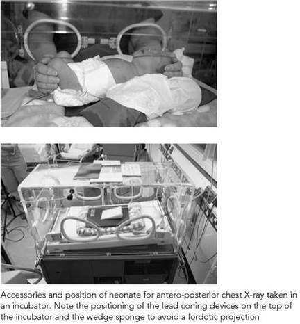
An 18 X 24-cm cassette that is at body temperature is selected. Disposable sheets should be used between the baby and the cassette. Modern incubators with cassette trays can be used to avoid disturbance of a very sick baby (see below).
Position of patient and cassette
Sleeping baby
• The baby is positioned supine on the cassette, with the median sagittal plane adjusted perpendicular to the middle of the cassette, ensuring that the head and chest are straight and shoulders and hips are level.
• The head may need a covered sandbag support on either side. A 10-degree foam pad should be placed under the shoulders to avoid a lordotic projection and to lift the chin and prevent it obscuring the lung apices.
• Arms should be on either side, separated slightly from the trunk to avoid being included in the radiation field and to avoid skin crease artefacts, which can mimic pneumothoraces.
• Arms can be immobilized with Velcro bands and/or sandbags.
Baby requiring holding
Positioning is similar to that described for the sleeping baby and can be performed by a single assistant with the following adaptations:
• The arms should be held flexed on either side of the head.
• Arms should not be extended fully, as this can cause lordotic images.
• When needed, legs should be held together and flexed at the knees.
Direction and centring of the X-ray beam
• No single centring point is advised.
• Centre the beam to the midline of the cassette.
• The central ray is directed vertically, or angled five to 10 degrees caudally if the baby is completely flat, to avoid projecting the chin over the lung apices.
• Constant maximum FFD should be used.
• Although some incubators have cassette trays, placing the cassette under the baby is recommended as routine, to avoid magnification and change of exposure factors.

Chest - neonatal
Antero-posterior - supine
Essential image characteristics
• Peak inspiration to include eight to nine posterior ribs (four to five anterior ribs).
• No rotation. Medial ends of the clavicles should overlap the transverse processes of the spine symmetrically, or anterior rib ends should be equidistant from the spine.
• No tilting or lordosis. Medial ends of the clavicles should overlie the lung apices.
• Superior/inferior coning should be from cervical trachea to T12/L1, including the diaphragms.
• Lateral coning should include both shoulders and ribs but not beyond the proximal third of the humeri.
• Reproduction of the vascular pattern in the central two- thirds of the lungs.
• Reproduction of the trachea and major bronchi.
• Visually sharp reproduction of the diaphragm and costophrenic angles.
• Reproduction of the spine and paraspinal structures.
• Visualization of retrocardiac lung and mediastinum.
• Visually sharp reproduction of the skeleton.
Common faults and remedies
• Classically, the port hole of the incubator must not overlie the chest.
• All extraneous tubes and wires should be repositioned away from the chest area.
• Exposure should be made in inspiration. Watching for full distension of the baby’s abdomen rather than the chest best assesses this. Expiratory images mimic parenchymal lung disease.
• Arms should not be extended fully above the head, as this will lead to a lordotic position.
• Lordotic images show anterior rib ends pointing upwards, and the lung bases are obscured by the diaphragm.
• The head must be supported to avoid the chin lolling forward and obscuring the upper chest.
• Minimal exposures of less than 0.02 seconds should be used to avoid motion artefact.
• Rotated images should be avoided, as this can cause misinterpretation of mediastinal shift and lung translucency. The separate ossification centres of the sternum, projected over the lungs can also cause confusion.
• As in all radiographs, but particularly in neonatal work, where the name label is large compared with the size of the image, the label should not obscure any of the anatomical detail.
• Taking a radiograph when a baby is crying should be avoided, as this can cause overexpansion of the lungs, which may mimic pathology.
• Overexposure of neonatal chest radiographs results in loss of lung detail.
Chest - neonatal
Antero-posterior - supine (contd)
Radiological considerations
• If the baby is intubated, great care must be taken not to dislodge the endotracheal tube. Even small movements of the head can result in significant movement of the tip. This should lie in the lower third of the trachea, approximately between T1 and the carina.
• An umbilical arterial catheter (UAC) follows the umbilical artery down inferiorly to either internal iliac artery and then via the iliacs to the aorta. This catheter is usually finer and more radio-opaque than an umbilical venous catheter (UVC). The former should ideally be placed with its tip in the mid-thoracic aorta between T4 and T9, which avoids the risk of causing thrombosis if the tip is opposite the origins of any of the abdominal vessels. Some UACs can be left with their tips in the lower abdominal aorta if there has been difficulty with advancing them. The UVC passes directly upwards through the ductus venosus in the liver and should lie with its tip in the IVC or right atrium. If lines are only faintly radio-opaque, then 0.5 ml of non-ionic intravenous contrast (iodine 200mg/ml) can be used for opacification.

Notes
• Minimal handling and the avoidance of heat loss from any incubator are essential. Babies are very vulnerable to infection, and therefore strict hygiene rules and hand-washing are paramount.
• All the cassettes and foam pads inserted into an incubator should be washable.
• Experienced nursing help in immobilization techniques is invaluable.
• All preparation of the X-ray equipment should be performed before placing the X-ray cassette under the baby.
Image of chest and abdominal radiograph post insertion of UAC and UVC

Image of antero-posterior chest in a neonate with pulmonary interstitial emphysema of the right lung and a chest drain draining a left pneumothorax
Radiation protection
• Accurate collimation of the X-ray beam using light beam diaphragm with additional lead masking within the primary field balanced on top of incubator.
• It is the radiographer's responsibility to ensure that the holder's hands are not in the direct beam.
• The abdomen should be included on a chest radiograph only if assessment of catheters or relevant pathology is present. In this case, male gonads should be protected.
• All mobile equipment on SCBU should have short-exposure capability to allow kVp selection of over 60 kV as a dose- reduction measure. If this is not possible, then additional filtration can be considered, but this can affect the quality of the image.
• An accurate exposure chart according to infant weight should be available.
• All mobile equipment should have a dose area product meter.

Image of antero-posterior chest poorly positioned due to the neonate being rotated; the normal right lobe of thymus obscures the right upper lobe

Image antero-posterior chest with shadow of incubator port hole overlying the left diaphragm, ECG clips obscuring right hemithorax and right upper lobe consolidation


Chest - post-neonatal
Recommended projections
Examination is performed by means of the following projections:
|
Basic |
Postero-anterior - erect |
|
Alternative |
Antero-posterior - erect Antero-posterior - supine |
|
Supplementary |
Lateral Antero-posterior with Cincinnati filter |
There is some controversy as to whether chest radiographs of children beyond the neonatal period should be taken supine or erect and postero-anterior or antero-posterior.
It is recommended that a postero-anterior erect projection should be adopted when a child can stand or when age allows. This results in a lower breast dose. An erect projection also allows better expansion of the lungs and demonstration of pleural effusions and pneumothoraces. However, if this is not possible, then supine projections are taken. For all projections, it is important that the child should be straight, with no rotation.
Specific technique depends on the clinical referral, as follows.
Congenital heart disease
The dimensions of the small paediatric chest are such that the choice of postero-anterior/antero-posterior projection does not have such an influence on the impression of cardiac size, unlike in adults. However, in some cases of known congenital heart disease, it may be advisable to use the same projection for initial follow-up studies (Hochschild and Cremin 1975).
Inhaled foreign body
A high index of suspicion is required.
Use of fluoroscopy or an antero-posterior image of the chest using a Cincinnati filter should be performed where possible to demonstrate the trachea and mediastinum and any mediastinal shift. Otherwise, antero-posterior projections in inspiration and expiration, or, if under two years of age, horizontal beam radiography with the patient in each lateral decubitus position, may be performed to demonstrate air trapping in the obstructed dependent lung. All images should include the pharynx, trachea, major bronchi and lungs and should be as straight as possible to allow assessment of mediastinal shift.
Oesophageal pH probe for reflux study
A postero-anterior/antero-posterior rather than a lateral projection is preferred as it gives a lower dose. It should be coned in laterally to the mediastinum, and the tip of the probe should be at T7/T8. (See image on p. 395.)
Radiation protection
• Very accurate collimation using light beam diaphragm. The four edges of the cones should be visible on the radiograph. The X-ray beam should not be coned to the cassette edges.
• Adequate immobilization essential.
• Postero-anterior projection to reduce breast dose.
• Holder should wear a lead-rubber apron and stand to the side.
Postero-anterior - erect
The key to erect chest radiography is a specifically designed paediatric chest stand. The cassette holder should be in such a position that a parent or carer is able to hold the child easily. A cassette is selected relative to the size of the child.
Position of patient and cassette
• Depending on the child's age, the child is seated or stood facing the cassette, with the chest pressed against it.
• The arms should be raised gently, bringing the elbows forward. The arms should not be extended fully.
• The parent or carer should hold the flexed elbows and head together and pull the arms gently upwards and slightly forward to prevent the child from slumping backwards.

Direction and centring of the X-ray beam
• The horizontal central beam is directed at right-angles to the midline of the cassette at the level of the eighth thoracic vertebra (spinous process of T7).
Antero-posterior - erect
This is done when the postero-anterior projection is not possible.
Position of patient and cassette
• The child is seated with their back against the cassette, which is supported vertically, with the upper edge of the cassette above the lung apices.
• The arms should be raised gently, bringing the elbows forward. The arms should not be extended fully.
• The parent or carer should hold the flexed elbows and head together with their fingers on the forehead, to prevent the child's chin from obscuring the upper chest.
• The holder should pull gently upwards to prevent the child from slumping forward.
• Place a 15-degree foam wedge behind the shoulders to prevent the child from adopting a lordotic position.
Direction and centring of the X-ray beam
• The horizontal central beam is angled five to ten degrees caudally to the middle of the cassette at the level of the eighth thoracic vertebra, approximately at the midpoint of the body of the sternum. This is particularly important in children with hyperinflated chests due to diseases such as bronchiolitis, which predisposes to lordotic projections.
• The radiation field is collimated to the cassette, thus avoiding exposure of the eyes, thyroid and upper abdomen.
Notes
• A comfortable seat, with Velcro straps encased in foam that can be applied over the thighs, is extremely useful.
• Mobile lead shielding (see p. 389).


Image of normal postero-anterior erect chest

Image of postero-anterior erect chest showing dense right hilum and RUL bronchiectasis in a patient with TB

Coned antero-posterior supine chest X-ray to show the position of pH probe which should be at the level of T7/T8
Postero-anterior/ antero-posterior - erect
• Correct interpretation of paediatric chest radiographs requires images taken in maximum inspiration without rotation or tilting. The radiographer should watch the child's chest/ abdominal movements to obtain a maximum inspiration.
Common faults and remedies
• Incorrect density - needs radiographer experience in assessing the size of the child and careful exposure charts.
• Thorax tilted backwards (antero-posterior projection), with clavicles shown high above the lung apices. This lordotic projection results in the lower lobes of the lungs being obscured by the diaphragms. Pneumonia and other lung pathology can be missed. See Position of patient and cassette for how to correct this fault.
• Holder's hands on the shoulders - avoid by following the technique as described.
• Wide cones including arms, skull and abdomen on the radiograph should be avoided.
Essential image characteristics
Antero-posterior/postero-anterior projection:
• Peak inspiration (six anterior ribs (postero-anterior, 5/6 for antero-posterior) and nine posterior ribs above the diaphragm).
• Whole chest from just above the lung apices to include the diaphragms and ribs.
• No rotation (medial ends of clavicles or first ribs should be equidistant from the spine).
• No tilting (clavicles should overlie lung apices). Anterior ribs should point downwards.
• Reproduction of vascular pattern in central two-thirds of the lungs.
• Reproduction of the trachea and proximal bronchi.
• Visually sharp reproduction of the diaphragm and costophrenic angles.
• Reproduction of the spine and paraspinal structures and visualization of the retrocardiac lung and mediastinum.
Radiological considerations
• Chest radiographs are not required routinely for simple chest infections, and follow-up chest images are not required routinely if there has been a good response to treatment, unless the initial chest image showed lobar pneumonia, extensive sublobar pneumonia involving several segments, pneumato- coeles, adenopathy or pleural effusion.
• Follow-up radiographs, where indicated, should not be taken in less than three weeks, as radiological resolution lags behind clinical resolution. Repeat images are required earlier if there is any deterioration. Prompt follow-up chest radiography is required following physiotherapy and antibiotics for areas of collapse.
Antero-posterior - supine
The antero-posterior (supine) projection is performed as an alternative to the erect position when the latter is not possible.
Special attention is required when imaging a baby's chest. With the chest being conical in shape, positioning a baby supine with the back against a cassette results in a lordotic projection, with the clavicles projected above the apices and a large part of the lower lobes superimposed on the abdomen. The heart also appears foreshortened. In a correct projection, the anterior rib ends will be projected inferiorly to the posterior rib ends, and the clavicles will be seen superimposed on the lung apices. This can be accomplished either by leaning the baby forward or by angling the X-ray tube caudally, or both.
The projection is often performed as part of a mobile X-ray examination on children of all ages.
A cassette size is selected depending on the size of the child.
Position of patient and cassette
• The child is positioned supine on the cassette, with the upper edge positioned above the lung apices.
• When examining a baby, a 15-degree foam pad is positioned between the thorax and the cassette (thick end under the upper thorax) to avoid a lordotic projection. A small foam pad is also placed under the child's head for comfort.
• The median sagittal plane is adjusted at right-angles to the middle of the cassette. To avoid rotation, the head, chest and pelvis are straight.
• The child's arms are held, with the elbows flexed, on each side of the head.
• A suitable appliance, e.g. Bucky band or Velcro band, is secured over the baby's abdomen and sandbags are placed next to the thighs to prevent rotation.
Direction and centring of the X-ray beam
• The vertical central beam is directed at right-angles to the middle of the cassette at the level of T8 (mid-sternum).
• For babies with a very hyperinflated barrel chest (due to bronchiolitis or asthma), the tube is also angled five to 10 degrees caudally to avoid a lordotic projection.
Notes
• Care should be taken not to have the lung apices being obscured by the chin.
• Lead-rubber coverage of the abdomen in immediate proximity to beam is recommended.
Common faults and remedies
• Tilted, with clavicles high above the lung apices. This lordotic projection results in the lower lobes of the lungs being obscured by the diaphragms. Pneumonia and other lung pathology can


Child position for lateral projection of the chest

Lateral chest radiograph showing a pulmonary abscess and fluid level
Lateral
This supplementary projection is undertaken to locate the position of an inhaled or swallowed foreign body, to evaluate middle lobe pathology or to localize opacities demonstrated on the postero-anterior/antero-posterior projection. A 24 X 30-cm cassette is selected.
Position of patient and cassette
• The patient is turned to bring the side under investigation towards the cassette. The median sagittal plane is adjusted parallel to the cassette.
• The outstretched arms are raised above the head and supported.
• The mid-axillary line is coincident with the middle of the cassette, and the cassette is adjusted to include the apices and the inferior lobes.
Direction and centring of the X-ray beam
• Direct the vertical central ray at right-angles to the middle of the cassette in the mid-axillary line.
• Exposure is made on peak inspiration.
Essential image characteristics
• Peak inspiration (six anterior ribs above the diaphragm).
• Whole chest from C7 to L1.
• Sternum and spine to be included and to be true lateral.
• Visualization of whole trachea and major bronchi.
• Visually sharp reproduction of the whole of both domes of the diaphragm.
• Reproduction of the hilar vessels.
• Reproduction of the sternum and the thoracic spine.

Cincinnati filter device
The use of this filter device is employed in cases of suspected inhaled foreign body when an antero-posterior image of the chest is acquired with the child lying supine.
The Cincinnati filter is composed of 2 mm of aluminium, 0.5 mm of copper and 0.4 mm of tin inserted into the collimator box so that the copper layer is towards the -X-ray tube. Exposures used are in the range of 125-140 kVp and 10-16 mAs, using a cassette and grid system.
On the exposed radiograph, bone detail is effaced to a considerable degree, allowing soft tissue and air interfaces in the mediastinum and adjacent lung to be seen. The trachea and proximal bronchial anatomy are demonstrated well.
A CT scout scanogram can be considered as an alternative.
Careful handling is always advisable in children suspected to have an inhaled foreign body, as dislodgement can result in total airway obstruction.
Abdomen
Abdominal radiography of the acute abdomen in children is normally performed in conjunction with abdominal ultrasound. It is not routine in cases of non-specific abdominal pain, as a radiographic abnormality is unlikely to be demonstrated in the absence of any one of the following: loin pain, haematuria, diarrhoea, palpable mass, abdominal distension, or suspected inflammatory bowel disease.
Referral criteria will include suspected intussusception, chronic constipation (suspected Hirschprung’s disease), possible swallowed foreign body, and suspected necrotizing enterocolitis. More specific referral criteria of abdominal radiographs are given by Cook et al. (1998).
Modification to the standard technique is described on pp.400-401.
Recommended projections
Examination is performed by means of the following:
|
Basic |
Antero-superior - supine |
|
Alternative |
Postero-anterior - prone |
|
Supplementary |
Lateral Postero-anterior - left lateral decubitus Antero-posterior - erect |

Antero-posterior
Position of patient and cassette
• The child lies supine on the X-ray table or, in the case of a neonate, in the incubator, with the median sagittal plane of the trunk at right-angles to the middle of the cassette.
• To ensure that the child is not rotated, the anterior superior iliac spines should be equidistant from the cassette.
• The cassette should be large enough to include the symphysis pubis and the diaphragm.
Direction and centring of the X-ray beam
• The vertical central ray is directed to the centre of the cassette.
Notes
• All acute abdominal radiographs should include the diaphragms and lung bases. Lower-lobe pneumonia can often masquerade as acute abdominal pain.
• Radiographs for the renal tract can have more lateral coning, and a fizzy drink may be used to distend the stomach with air, thus displacing residue in the transverse colon and better demonstrating the renal areas.
• Collimation is as for adults, but babies’ and infants’ abdomens tend to be rounder; therefore, slightly wider lateral cones are required.
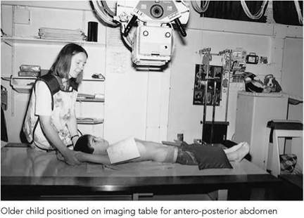


Image of antero-posterior abdomen of a male neonate showing intestinal obstruction due to small bowel atresia

Image of antero-posterior chest and abdomen in a female neonate with duodenal atresia
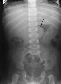
Image of an antero-posterior abdomen of a female infant with an intussusception in the transverse colon (arrow)
Antero-posterior
Essential image characteristics
Antero-posterior projection for whole abdomen:
• Abdomen to include diaphragm, lateral abdominal walls and ischial tuberosities.
• Pelvis and spine should be straight, with no rotation.
• Reproduction of properitoneal fat lines consistent with age.
• Visualization of kidney and psoas outlines consistent with age and bowel content.
• Visually sharp reproduction of the bones.
Common faults and remedies
• Usually inadequate coning but occasionally too tight coning excludes the diaphragm.
• Male gonads not protected.
• Careful technique is needed to address these problems.
Radiation protection
• Optimization of abdominal radiographs includes using a lower- dose technique, e.g. no grid and a very fast image acquisition system, in the assessment of examinations such as chronic constipation and swallowed foreign body is recommended. Serial images in the latter are not necessary.
• All boys should have testicular protection.
• Radiographs of the renal tract can be more collimated laterally (Cook et al. 1998).
• Although it has been demonstrated that a postero-anterior abdominal technique results in a lower dose (Marshall et al. 1994), a supine technique with male gonad protection is preferred in children.
• In supine neonates who cannot be moved, a horizontal beam lateral should be taken from the left to reduce the dose to the liver (see below).
Radiological considerations
• Unlike adults, erect images are rarely required or justified.
• Left lateral decubitus images may be required in cases of suspected necrotizing enterocolitis. In this projection, with the patient lying on the left side, free gas will rise, to be located between the lateral margin of the liver and the right abdominal wall.
• Lateral projections may demonstrate Hirschprung's disease or a retroperitoneal tumour in some rare cases.
• Abdominal ultrasound has replaced radiography in many conditions.
• In non-specific abdominal pain, radiographic abnormality is unlikely to be demonstrated in the absence of one of the following: loin pain, haematuria, diarrhoea, palpable mass, abdominal distension or suspected inflammatory bowel disease.
Modifications in technique
Constipation
• A very fast film/screen system should be used in chronic cases. A study of colonic transit time may also be requested.
• The patient swallows 30 radio-opaque plastic pellets and an antero-posterior radiograph with the child in the supine position is performed at day 5 following ingestion.
• If pellets are not present on day 5, this is normal.
• If there is a general delay in colonic transit, then the pellets will be distributed throughout the colon.
• If the pellets are grouped in the sigmoid/rectum, then there is poor evacuation.
• A medium-speed screen/film system is used in children under two years of age when Hirschprung's disease is suspected.
• All images should allow adequate assessment of the spine.
Suspected swallowed foreign body
• The initial radiograph should be with a fast-speed screen/film system to include the neck and upper abdomen.
• The radiograph should demonstrate the mandible to iliac crests. Lead protection should be used.
• The most likely sites of hold-up are the neck, midoesophagus where the left main bronchus crosses the oesophagus, and at the gastro-oesophageal junction.
• If a foreign body is demonstrated in the neck or chest, a lateral radiograph should be taken to confirm position.
• If history is less than four hours and the foreign body is in the oesophagus, the child should be given a fizzy drink, kept erect and an antero-posterior radiograph repeated in 30 minutes to see whether the foreign body has been dislodged.
• If history is greater than four hours, the patient should be kept nil by mouth and referred for consideration of physical removal.
• If no foreign body is demonstrated, no further radiographs are required unless the patient returns with symptoms of abdominal pain and vomiting. A supine abdominal radiograph should then be performed.
• Parents should always be advised to return if any of these symptoms develop, but pressure to obtain serial radiographs of foreign bodies passing through the abdomen should be resisted strongly, as this involves unnecessary exposure without any added benefit.
• In cases of lead acid or mercury batteries, the radiographs are acquired as described above. However, if the battery is still in the stomach, then it can react with gastric acid. Therefore, the child is normally given metoclopramide and the abdominal radiograph repeated in 24 hours. If the battery is still in the stomach, surgical referral is normally advised.
• Open pins and needles are occasionally swallowed. Surprisingly, most pass unhindered if they are beyond the oesophagus; therefore, the same radiographs are indicated as above.
• If a swallowed foreign body is suspected to be radiolucent, then a contrast study may be indicated.

Image of antero-posterior abdomen taken at five days showing delayed transit

Image of chest and upper abdomen showing coin-shaped foreign body overlying the stomach

Image of antero-posterior abdomen showing improved visualization of the kidneys in an IVU series following a fizzy drink to cause gaseous distension of the overlying stomach
NB: the use of a metal detector in determining the presence of a metal object in the abdomen may reduce the need for unnecessary irradiation of a child (Arena and Baker 1990, Ryan and Tidey 1994).

Photograph of neonate in left lateral decubitus position. For minimal handling, dorsal decubitus is an alternative

Image of antero-posterior abdomen, left lateral decubitus with free air around the liver and dorsal decubitus with free air anteriorly
Photograph of position of baby for lateral abdomen ventral decubitus

Images of lateral abdomen, ventral decubitus in imperforate anus. Lower limit of air-filled bowel is demonstrated in relation to the pubococcygeal line. Left: high obstruction with lead pellets at anatomical position of anus; right: low obstruction with barium-filled tube tip at level of anus
Modifications in technique
Suspected necrotizing enterocolitis
• An antero-posterior supine abdominal radiograph is obtained, with the legs and arms held in a similar position to that described for the neonatal chest radiograph in a nonsleeping infant (see p. 390).
• The abdomen is normally distended in these cases. Care must be taken not to collimate within the margins of the abdomen.
• If a perforation is suspected, an antero-posterior (left lateral decubitus) projection is selected using a horizontal beam, with the child lying in the lateral position. The right side of the patient is positioned uppermost, as it is easier to demonstrate free air around the liver. The patient should be kept in this position for a few minutes before the radiograph is taken to allow the air to rise.
• If the infant is too ill to be moved, then a lateral (dorsal decubitus) projection is preferred, using a horizontal beam, with the tube directed to the left side of the abdomen to reduce the dose to the liver. This requires less exposure than the antero-posterior projection.
• Lead protection should be used for boys.
Suspected diaphragmatic hernia
A combined antero-posterior chest and abdomen radiograph is recommended.
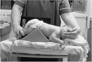
Imperforate anus (prone invertogram)
A lateral (ventral decubitus) projection is selected using a horizontal beam. This allows intraluminal air to rise and fill the most distal bowel to assess the level of atresia. Radiography should not be performed less than 24 hours after birth.
Position of patient and cassette
• The infant should be placed in the prone position, with the pelvis and buttocks raised on a triangular covered foam pad or rolled-up nappy.
• The infant should be kept in this position for approximately 10-15 minutes.
• The cassette is supported vertically against the lateral aspect of the infant's pelvis, and adjusted parallel to the median sagittal plane.
Direction and centring of the X-ray beam
• The horizontal central ray is directed to the centre of the cassette.
Note
A lead marker is taped to the skin in the anatomical area where the anus would normally be sited. The distance between this and the most distal air-filled bowel can then be measured.
• The lateral view should include the first three cervical vertebrae.
• A horizontal beam lateral is usually performed but is not considered essential before the age of six years, as the sphenoid sinus is not pneumatized before this age. After this, air fluid levels might indicate a base of skull fracture. All trauma images should demonstrate adequately the soft tissues.
Craniosynostosis
• For assessment of craniosynostosis, a lateral and under-tilted fronto-occipital, 20 degrees caudad projection will demonstrate all the sutures adequately in most children.
• Tangential views may be required in some cases of a bony lump.
A detailed description of adult skull radiography is given on pp. 238-245 and the techniques described can be readily adopted for older children. The projections described in the following pages are for a one-year-old child and are typical of most departments. The projections are:
• fronto-occipital;
• fronto-occipital - 30 degrees caudad;
• lateral of affected side with horizontal beam.
Radiological considerations
As skull X-rays involve a moderately high dose in terms of plain radiographs, often including a series of radiographs, justification is essential. Good clinico-radiological cooperation, agreed referral criteria and audit are essential in keeping the number of unnecessary radiographs to a minimum (Cook et al. 1998). Some studies suggest that over a third of requests following trauma are unnecessary (Boulis et al. 1978), and many have reported that absence of a fracture does not alter management (Garniak et al. 1986, Lloyd et al. 1997, Masters et al. 1987).
Radiation protection
• Justification, optimization and careful technique are the best ways of conforming to radiation protection guidelines.
• Avoidance of the use of a grid in children under the age of one year is an important dose-saving measure.
• A short exposure time is particularly important in performing skull radiography to avoid movement unsharpness. The maximum exposure time should be less than 40 ms.
• Children's skulls are almost fully grown by the age of seven years; therefore, children over this age need almost as much exposure as an adult.
• The hands of the person holding the child should not be visible on the radiograph.
• Tight collimation with circular cones of variable size is best suited for the shape of the cranium. In this way, unnecessary thyroid radiation can also be avoided in non-trauma cases. The collimation can be inserted above the diamentor chamber (see p. 388).
• Occipito-frontal projections, where possible, will reduce the dose to the eyes (Rosenbaum and Arnold 1978).

Obtaining diagnostic quality radiographs of the skull in small children is probably one of the most difficult challenges to any radiographer. The technique described for adults is not so straightforward when the patient is a screaming, red-faced, determined toddler accompanied by anxious parents.
Young children may be wrapped in cotton blankets for immobilization. The use of shaped foam pads is strongly recommended.
A feed or use of a pacifier is very beneficial. All clothing, fasteners, hair clips, beads and extra-stiff hair gel need to be removed. The carer accompanying the child, provided the carer is not pregnant, should be encouraged to distract the child with a toy for the exposure.
Children's head sizes are variable and also are of variable density, depending on skeletal maturation and various congenital malformations. Below the age of one year, there are no visible vascular markings, and it is only the range of additional sutures that can cause confusion with fractures. Grids are not used routinely in skull radiography of children under the age of one year, which allows for shorter exposure times and reduced patient dose. If an isocentric skull unit is used, the grid should be removed for children up to the age of one year.
Referral criteria
Referral criteria for skull projections include those specific recommendations by the RCR (2003) on the management of head injury.
Recommended projections
Examination is performed by means of the following:

Position of infant for antero-posterior skull with triangular sponges supporting the head on either side
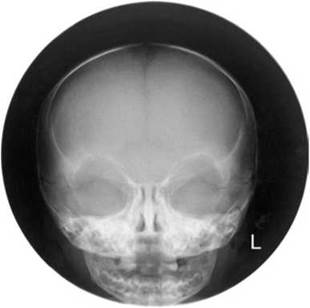
Image of normal fronto-occipital skull radiograph
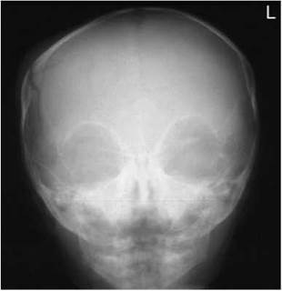
Image of a fronto-occipital skull radiograph of an infant demonstrating a right parietal fracture
Fronto-occipital
A 24 X 30-cm or 18 X 24-cm cassette is selected, depending on
the size of the cranium.
Position of patient and cassette
• The child is positioned carefully in the supine position, with the head resting on a pre-formed foam pad positioned on top of the cassette. The head is adjusted to bring the median sagittal plane at right-angles to and in the midline of the cassette. The external auditory meati should be equidistant from the cassette.
• The child is immobilized in this position with the assistance of a carer, who is asked to hold foam pads on either side of the skull during the exposure. The carer usually stands at the head end of the imaging table to undertake this procedure. Occasionally, a second carer is required to assist in keeping the child still.
Direction and centring of the X-ray beam
• The central ray is directed to the nasion at the necessary angle to allow it to pass along the orbito-meatal plane.
• If it is required that the orbits are shown clear of the petrous bone, the central ray should be angled cranially so that it makes an angle of 20 degrees to the orbito-meatal plane and centred to the nasion.
Essential image characteristics
• Whole cranial vault, orbits and petrous bones should be present on the radiograph and should be symmetrical.
• For occipito-frontal 20 degrees, petrous bones should be projected over the lower orbital margins.
• Lambdoid and coronal sutures should be symmetrical.
• Visually sharp reproduction of the outer and inner tables of the cranial vault according to age.
• Reproduction of sinuses and temporal bones consistent with age.
• Visualization of the sutures consistent with age.
• Soft tissues of scalp should be reproduced with a bright light.
Common faults and remedies
• Holder's hands around the face.
• Wide cones.
• Rotated patient with respect to the cassette.
• Whole cervical spine or upper chest unnecessarily on the radiograph.
• Use of a feeding bottle or pacifier often allows the correct position to be maintained.
• Obtaining the child's confidence and following the advice in positioning the patient should avoid these problems.
Fronto-occipital - 30 degrees caudad
Position of patient and cassette
• The child is positioned in a similar way to that described for the fronto-occipital position. However, the chin is depressed so that the orbito-meatal line is at right-angles to the table.
• The carer immobilizes the head using foam pads positioned gently but firmly either side of the head.
• The cassette is positioned longitudinally on the tabletop, with its upper edge at the level of the vertex of the skull.
Direction and centring of the X-ray beam
• The central ray is angled caudally so that it makes an angle of 30 degrees to the orbito-meatal plane.
• To avoid irradiating the eyes, a collimation field is set such that the lower border is coincident with the upper orbital margin and the upper border includes the skull vertex. Laterally, the skin margins should also be included within the field (Denton 1998).
• If the child’s chin cannot be sufficiently depressed to bring the orbito-meatal line at right-angles to the table, it will be necessary to angle the central ray more than 30 degrees to the vertical so that it makes the necessary angle of 30 degrees to the orbito-meatal plane.
Essential image characteristics
• The arch of the atlas should be projected through the foramen magnum.
• Lambdoid and coronal sutures should be symmetrical.
• Inner and outer table, soft tissues and sutures as above.


Position of a six-month-old child for lateral skull with horizontal beam technique with patient supine demonstrating immobilization and distraction with a feeding bottle

Position of a 3-year-old child positioned for lateral skull, patient supine showing use of foam pad to immobilize the head

Position of 6-year-old child for lateral skull, patient supine showing position of X-ray tube

Image of correctly positioned lateral radiograph of a baby's skull
Lateral - supine
Position of patient and cassette
• With the patient supine on the Bucky table, a pre-formed foam pad is placed under the head so that the occiput is included on the image.
• The patient's head is now adjusted to bring the median sagittal plane of the head at right-angles to the table by ensuring that the external auditory meati are equidistant from the table.
• The head is immobilized with the aid of a carer (see photographs opposite for technique according to age).
• A cassette is supported vertically against the lateral aspect of the head parallel to the median sagittal plane, with its long edge 5 cm above the vertex of the skull.
Direction and centring of the X-ray beam
• The horizontal central ray is directed parallel to the interorbital line so that it is at right-angles to the median plane and the cassette.
• The central ray is centred midway between the glabella and the external occipital protuberance.
Essential image characteristics
• The whole cranial vault and base of the skull should be present and symmetrical.
• The floor of the pituitary fossa should be a single line.
• The floors of the anterior cranial fossa should be superimposed.
• The mandibular condyles should be superimposed.
• The first three cervical vertebrae should be included for trauma and should be lateral.
• Visually sharp reproduction of the outer and inner tables and floor of the sella consistent with age.
• Visually sharp reproduction of the vascular channels and trabecular structure consistent with age.
• Reproduction of the sutures and fontanelles consistent with age.
• Reproduction of the soft tissues and nasal bones, consistent with age.
• Reproduction of sphenoid sinus (not pneumatized below the age of six years).
Sinuses
Maxillary antra are not well pneumatized before the age of three years and the frontal sinuses are not developed before the age of six years. Sinus X-rays are therefore rarely justified in children below this age. An occipito-mental projection of the sinuses is performed erect in a similar way to that described for adults (see p. 263). However, in children the patient's nose and mouth are first placed in contact with the midline of the vertical Bucky and then the head is adjusted to bring the orbito-meatal line at 35 degrees to the horizontal at the centre of the Bucky.
Essential image characteristics
• The X-ray beam should be well collimated and should include the frontal sinuses (when developed in children over six years of age) and the bases of the maxillary sinuses and upper maxillary teeth.
• Petrous bones should lie at the base of the antra.
• Orbits, sinuses and petrous bones should be symmetrical.
• Bony detail should have visually sharp reproduction.
• Soft tissues and mucosa of sinuses should be visible.

Image of occipito-mental projection of facial bones of a 13-year-old boy demonstrating a blowout fracture of the left inferior orbital margin with fluid levels in the left maxillary antrum and left frontal sinus
Post-nasal space - lateral supine
PNS radiography is usually performed on children between four and 10 years of age, with the common problem of mouth breathing due to nasal obstruction. A lateral projection (taken supine) of the PNS is performed to demonstrate enlarged adenoids, hence the PNS must be air-filled to be radiographically visible.
Position of patient and cassette
• The child lies supine on the table, with the lateral aspect of the head in contact with a cassette supported vertically. The head is adjusted to bring the medial sagittal plane parallel to the cassette.
• The jaw is raised slightly so that the angles of the mandible are separated from the bodies of the upper cervical spine.
Direction and centring of the X-ray beam
• The horizontal beam is centred to the ramus of the mandible, and coned to include the maxillary sinuses to the third cervical vertebrae and the posterior pharynx.
Note
The image should be taken with the mouth closed. If the PNS is obliterated, the view should be repeated with the child sniffing.

Child positioned for lateral projection of face for PNS

Image of lateral projection of PNS in a 6-year-old child
Essential image characteristics
• The condyles of the mandible should be superimposed.
• Bony detail should have visually sharp reproduction.
• Soft tissue of adenoidal pads should be reproduced.


Dental radiography
Cephalometric radiography and dental panoramic tomography (DPT) are now the most commonly requested imaging techniques in teenagers due to the increasing requirement for orthodontics. These types of radiographs should not be performed routinely in children under the age of seven years for orthodontic assessment alone. However, paediatric dentists often request DPT on children from three years onward to demonstrate 'state of teeth' before dental treatment. This should be performed only if extensive caries are present. Special attention must be given to justification of exposure and optimization, collimation and avoiding unnecessary repeats.
A detailed description of the radiographic techniques in adults is given in Section 10.
• For lateral cephalometry, in addition to the graduated filter, a triangular coning device is recommended to avoid irradiating the back of the skull and the thyroid.
• The whole skull will need to be demonstrated in cranio-facial deformity.
• CT lateral cephalolometry can also be considered as a low- dose alternative.
• For DPT, additional eye shields are also recommended, where only a fixed aperture is available.


Pelvis/hips
Initial pelvic and hip radiography is normally performed in conjunction with ultrasound. Radiation protection measures should be applied strictly. The examination is undertaken using a fast screen/film system, with no grid in children under the age of three years, to ensure that the patient dose is kept to a minimum. The size of the cassette will depend on the age and size of the child.
Radiography may be performed before or during treatment, when a child may present wearing a special splint or plaster-cast.
Referral criteria
• hip pain/limp (irritable hips, Perthes' disease, slipped upper femoral epiphysis, osteomyelitis);
• development dysplasia of the hip (DDH)/congenital dislocated hip (CDH);
• trauma;
• post-surgery;
• part of a skeletal survey for NAI or suspected syndrome.
Recommended projections
The antero-posterior projection is the most commonly requested projection for children of all ages.
Examination is performed by means of the following:
|
• DDH/CDH |
• Antero-posterior - supine • Antero-posterior - erect |
|
• Irritable hips |
• Antero-posterior • Lateral - frog view |
|
• Post op for slipped epiphysis |
• Antero-posterior - supine • Turned lateral |
|
• Trauma |
• Antero-posterior - supine • Lateral - horizontal beam |
Antero-posterior
The following describes the technique adopted for a three-month-old baby. A cassette is selected that is large enough to include the pelvis and upper femora.
Position of patient and cassette
• The child lies supine on the X-ray table, on top of the cassette or a specially designed cassette holder, which is placed at the end of the table, with the median sagittal plane of the trunk at right-angles to the middle of the cassette.
• To maintain this position, a sandbag is placed on either side of the baby's trunk, with the child's arms left unrestrained.
• The baby's legs are held straight, with the holder's hands positioned firmly around each leg, the holder's fingers under the baby's calves and the holder's thumbs on the knees.
• If using the cassette holder at the end of the table, the knees should be held together and flexed.

Male child positioned for antero-posterior supine projection of hips with window protection

Image of an antero-posterior pelvis showing window gonad protection with additional female protection over the gonads

Four-month-old baby boy positioned for hips in an immobilization device with shaped lead protection
• For the older child, positioning is similar to that described for the adult (see p. 148).
Direction and centring of the X-ray beam
• The vertical central ray is directed to the centre of the cassette.
Note
Following surgery, low-dose CT may be used to demonstrate the position of the femoral head in patients treated with the use of a long-term plaster cast.


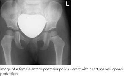

Antero-posterior - erect (weight-bearing)
As soon as a child is able to stand, weight-bearing erect images are frequently requested.
• The child stands with the posterior aspect of the pelvis against a cassette held vertically in the cassette holder.
• The anterior superior iliac spines should be equidistant from the cassette and the median sagittal plane vertical and coincident with the centre of the cassette.
• The ankles should be apart and separated by a small 40-degree foam pad, with the toes straight and pointing forwards.
• The child is supported at the waist whilst standing on a raised platform, with sandbags secured around the feet. Any pelvic tilt is corrected with the use of a small block.
Essential image characteristics
• Whole pelvis, sacrum and subtrochanteric regions of both femora. (Iliac crests can be excluded in specific hip pathology, e.g. Perthes' disease.)
• Symmetrical, with iliac wings and pubic rami of equal length. Femoral necks should not be foreshortened.
• Visualization of sacrum and intervertebral foramina depending on bowel content and presence of female protection. Reproduction of sacro-iliac joints according to age, with reproduction of the femoral necks.
• Reproduction of spongiosa and cortex.
• Visualization of trochanters consistent with age.
• Visualization of soft tissue planes.
Common faults and remedies
• Rotated patient with respect to the cassette needs careful observation of supine patient and holding technique.
• Gonad protection missing, inadequate, too large or slipped over region of interest. Gonad protection is most necessary during hip radiography. A very careful technique is required. A wide range of sizes and types are required. Experience is essential.
Radiation protection
• Gonad protection is not used for the initial examination.
• Subsequent examinations require the use of gonad protection. If erect position is required, then gonad protection can be taped into position. Alternatively, a window-shaped coning device can be inserted beneath the light beam diaphragm.
Radiological considerations
• Hip radiographs are a common request in children, but initial ultrasound examination should always be considered.
• A line drawn from the mid-sacrum through the triradiate cartilage should pass through the medial aspect of the femoral metaphysis to exclude dislocation. Similarly, Shenton's line (along superior obturator foramen and femoral neck) should be uninterrupted.
Von Rosen projection
This supplementary projection was sometimes employed to confirm diagnosis of DDH. The disadvantage of the projection is that it produces a number of false positives and negatives, and it has been largely superseded by hip ultrasound.
The ossification centre of the femoral head tends to be a little eccentric and lateral, particularly following treatment for DDH. This may give the false impression of decentring. The degree of dislocation and decentring is best assessed by drawing a line through the mid-sacrum and triradiate cartilage. This line should pass through the medial aspect of the femoral metaphysis. The use of this line in a straight antero-posterior radiograph of the hips is preferred to the Von Rosen projection.
Lateral - both hips (frog projection)
This projection may be employed to supplement the anteroposterior projection in the investigation of irritable hips.
Position of patient and cassette
• The child lies supine on the X-ray table, on top of the cassette, with the median sagittal plane of the trunk at right- angles to the middle of the cassette.
• To maintain this position when examining a baby, a sandbag is placed either side of the baby's trunk, with the arms left unrestrained.
• The anterior superior iliac spines should be equidistant from the couch top to ensure that the pelvis is not rotated.
• The hips and knees are flexed.
• The limbs are then rotated laterally through approximately 60 degrees, with the knees separated and the plantar aspects of the feet placed in contact with each other.
• A child may be supported in this position with non-opaque pads.
• The cassette is centred at the level of the femoral pulse and must include both hips.
Direction and centring of the X-ray beam
• The vertical central ray is directed in the midline at the level of the femoral pulse.

Image of antero-posterior hips with SUFE on left

Pelvis of an infant with a line drawn from the mid sacrum through the triradiate cartilage which should cross the medial upper femoral metaphysis showing obvious left dislocation
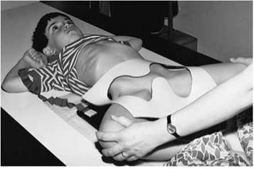
Child positioned for frog projection of hips with window protection
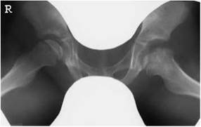
Image of male patient for frog projection of hips with window protection demonstrating bilateral Perthes' disease

Image of antero-posterior and turned lateral of left hip showing left femoral head Perthes' disease. Note: gonadal protection for all follow-up images
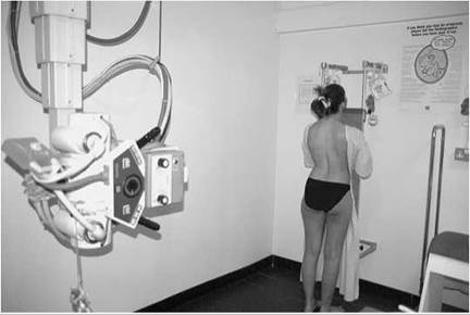
Photograph of patient positioned for postero-anterior projection spine

Postero-anterior erect spine showing example of initial image at presentation taken with a grid and limited collimation to include the thorax and abdomen. Cob angles demonstrated to measure the degree of lateral curvature

Photograph of lateral coning device used for follow-up studies
Spine - scoliosis
Scoliosis is a term for lateral curvature of the vertebral column. It is always accompanied by rotation of the involved vertebrae. The major part of the column is usually involved, since the primary curve (often found in the thoracic spine with the convexity to the right) subsequently gives rise to one or two compensatory secondary curves above or below it. Radiography is performed to assess the progression of the disease and to measure the effectiveness of conservative treatment or when surgical treatment is considered.
As the curvature normally will progress only while the skeleton is growing, the iliac crests on postero-anterior images are included so that the degree of maturity can be estimated from the degree of apophyseal fusion. Alternatively, the nondominant hand can be radiographed for bone age.
The majority of patients encountered will be children or adolescents, most commonly suffering from idiopathic scoliosis. Images will be taken at regular intervals as progression of the disease is monitored. Given the relatively high radiation doses associated with this examination, and the heightened radiosensitivity of children, radiation protection considerations are paramount (see below).
Referral criteria
The referral criteria for all types of pathology where a whole spine, rather than a segmental spine, examination is indicated are as follows:
• idiopathic/congenital/paralytic and post-infective scoliosis;
• spina bifida;
• suspected syndrome;
• severe injury;
• metastatic disease;
• metabolic disorder.
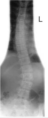
Postero-anterior erect spine showing example of follow-up study taken without a grid, with faster screen/film speed and tailored collimation to restrict the X-ray beam to the spine and avoid the developing breast
The projections required will vary considerably, depending on the stage of the disease, the age of the patient, treatment and the preferences of the orthopaedic surgeon. Close liaison between the radiology and orthopaedic departments is of paramount importance.
Image acquisition may be undertaken using conventional or digital radiography. Conventional radiography is described, and the reader is directed to the manufacturers' literature for details relating to digital acquisition and measurement procedures.
• A standing postero-anterior image is often all that is required.
• A lateral projection may be performed at the time of the initial investigation.
• Images may be required with the patient wearing a brace and repeated with the brace removed in order to monitor its effectiveness.
• Additional frontal images with the patient supine and recumbent, bending to each side may be requested to assess the degree of passive correction and determine the extent of any planned fusion.
• Postoperative radiographs of the chest are required to assess lung expansion and spinal radiographs to ensure integrity of the spinal instrumentation.
Postero-anterior - standing
A 35 X 43-cm cassette with a 400-speed film/screen system is selected and positioned in a chest stand or erect Bucky. A grid is used for the initial examination.
For examination of taller children, when it is not possible to include the whole spine on a 35 X 43-cm cassette, a specialized long cassette (typically 30 X 90cm or 35 X 105 cm) loaded with ungraduated screens is used and held erect in a special upright holder mounted on a wall.
Position of patient and cassette
• The patient stands with the anterior aspect of the trunk in contact with the vertical Bucky or grid cassette.
• The lower edge of the cassette is placed 1.5 cm below the iliac crests, with the chin resting on the top of the cassette to include from C7 to S1.
• The median sagittal plane should be at right-angles to the cassette and should coincide with the vertical centre line of the Bucky.
• The patient's arms should be by their sides, although it may be necessary to raise the arms of smaller children to assist in stretching the vertebral column.
• If the patient is standing, shoes should be removed and the feet placed slightly apart in the anatomical position to ensure that the patient is bearing weight equally on both legs.
• Occasionally, a wooden block (height previously determined) is positioned under one foot to correct for pelvic tilt.
• A line joining the highest point of the iliac crests should be horizontal if possible.

Photograph of patient in a brace positioned postero-anterior projection of the spine
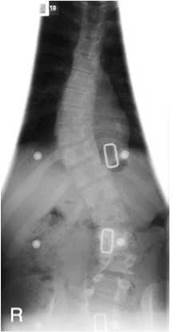
Image of a patient with spina bifida in a brace postero-anterior projection of the spine without a grid
• The middle of the cassette should be positioned just above the thoracolumbar junction (T11/T12 region).
Radiation protection
• The most effective protection for the breasts is to undertake the examination in the postero-anterior position.
• Follow-up examination does not require the same quality for definition as the initial examination.
• The grid can be dispensed with, unless the patient is particularly large.
• A fast screen/film system (700-800-speed) can be used. This can result in a dose reduction of 80% compared with the initial radiograph. The iliac crests do not need to be included for every radiograph.
• Developing breast tissue in adolescent females is highly radiosensitive; unnecessary irradiation of the breasts should be avoided where possible and breast shields considered.
• A pre-shaped filter device can be attached to the light-beam diaphragm (LBD) when undertaking conventional film radiography, to protect the developing breasts, ribs and gonads.

Image of postero-anterior spine erect without cones

Image of postero-anterior spine erect - patient bending to the right

Photograph of erect patient bending to the left
Postero-anterior - standing
Direction and centring of the X-ray beam
• A horizontal central ray is employed, and the beam is collimated and centred to include the whole spinal column.
• The lower collimation border is positioned just below the level of the anterior superior iliac spines, thus ensuring inclusion of the first sacral segment. The upper border should be at the level of the spinous process of C7.
• An increased FFD is used to ensure the correct cassette coverage (180-200 cm).
Notes
• For follow-up radiographs, a preshaped filter device of appropriate size is attached to the LBD to protect the developing breasts, ribs and gonads.
• If there is clinical suspicion of a structural abnormality then the cervical spine, ribs and hips may need to be included on the initial radiograph.
• It is important that the medial aspects of the iliac crests are not excluded to enable assessment of the spinal maturity from epiphysis growth.
Common faults and remedies
• It is important to ensure consistency in technique so that valid comparisons can be made. Note the technique and exposure factors employed and keep these with the patient's records for future reference. This will also help to reduce unnecessary repeats.
Essential image characteristics
• The first image should demonstrate the spine to include above and below the curvature, ribs and iliac crests (latter if aged 10-18 years in girls and 13-20 years in boys). For an idiopathic scoliosis, lower cervical spine to sacrum is adequate.
• If a structural abnormality is demonstrated, an antero-posterior cervical spine and additional coned views may be required.
• The image should give good reproduction of the vertebral bodies and pedicles, visualization of the posterior facet joints and reproduction of spinous processes and transverse processes consistent with age. Clear visualization of the endplates is required, essential for measuring the Cobb angle.
• Follow-up images should be coned to the spinal curvature and iliac crests as above.
Lateral
A 35 X 43-cm cassette with a 400-speed film/screen system is selected and positioned in a chest stand or erect Bucky. A grid is used for the initial examination.
Position of patient and cassette
• The patient stands with their bare feet slightly apart, with the side of the convexity of the primary curve against the vertical Bucky.
• Care is taken to ensure that the patient does not lean towards the cassette.
• The lower edge of the cassette is placed 1.5 cm below the iliac crests.
• The mid-axillary line is centred to the cassette. The coronal plane should be at right-angles to the cassette.
• The latter may be assessed by palpating the anterior iliac spines and rotating the patient so that a line joining the two sides is at right-angles to the cassette.
• Similarly, a line joining the lateral end of the clavicles should be at right-angles to the cassette.
• The arms are folded over the head.
Direction and centring of the X-ray beam
• A horizontal central ray is employed, and the beam is collimated and centred to the cassette to include the whole spinal column.
• The lower collimation border is positioned at the level of the anterior superior iliac spines, thus ensuring inclusion of the first sacral segment.
• The upper border should be at the level of the spinous process of C7.
• An increased FFD is used to ensure the correct, whole anatomical area is covered (180-200 cm).
Notes
• Care should be taken to ensure that the beam is well collimated to exclude the breast tissues, especially in follow-up radiographs.
• Additional views, fluoroscopy, CT or MRI may be required to reveal the complete extent of the 3-dimensional nature of some severe deformities.

Patient positioned for lateral projection of the spine

Image of lateral whole spine using Image of postero-anterior whole spine grid and cones collimated to the scoliosis and uncorrected pelvic tilt spine using a long cassette

Radiological considerations
• The most common referral for scoliosis is now idiopathic scoliosis. Affected children are otherwise completely normal, with a normal life expectancy. Multiple radiographs for monitoring are required, and therefore dose-saving measures are important.
• Scoliosis is described as being of early onset (before five years) and late onset. Those who develop large curves early have a higher risk of developing cardiovascular complications.
• Secondary spinal scoliosis is now less common in most centres. The main causes being: congenital (including hemivertebrae), neuromuscular disorders and neurofibromatosis. Tuberculosis is uncommon and polio is now rare. However, it is still extremely important to exclude underlying disease and MRI or scintigraphy is advised in all patients with atypical 'idiopathic' scoliosis or painful scoliosis (the latter typically being due to an osteoid osteoma). MRI should also be considered preoperatively to exclude lesions such as syringomyelia.
• When a secondary scoliosis is suspected due to abnormalities seen on the first thoraco-lumbar spine image, coned views, cervical spine and pelvic radiographs can be considered for additional assessment.
• The lateral curvature of an idiopathic scoliosis is usually convex to the right giving a right-sided hump and is accompanied by rotation of the vertebrae on a vertical axis. This thrusts the ribs backwards in the thoracic area and increases the ugliness of the deformity. The rotary component makes the disease more complex than a cosmetic deformity and rotation of the thorax can lead to compression of the heart and lungs, whereas lumbar curves can predispose to later degenerative changes.
• The goal of therapy is to keep the primary curve less than 40 degrees at the end of growth; small curves of less than 15 degrees are usually not treated. Curves of 20-40 degrees are managed in a body brace, and curves of more than 40 degrees usually have spinal fusion (e.g. a metal Harrington rod). Follow-up images of patients with a Harrington rod will need to show any breakage of the rods or surrounding Luque wiring.
• An assessment of skeletal age is required so that appropriate treatment can be planned. The development of the iliac apophyses (Risser's sign) correlates well with skeletal maturity, as determined by assessing bone age at the hand and wrist (Dhar et al. 1993). The iliac apophyses first appear laterally and anteriorly on the crest of the ilium. Growth develops posteriorly and medially, followed by fusion to the iliac crests. Increasing ossification correlates with decreased progression.
Spine - cervical, thoracic and lumbar
This section addresses modifications in technique for the cervical spine for those patients aged four years and under. Readers are referred to Section 6 for guidance in the technique for the adult spine.
Referral criteria for the spine as a whole are slightly different and include:
• low back pain (any back pain is abnormal in a child);
• scoliosis (the whole spine should be performed as described for whole spine);
• lower motor neuron signs in legs/neuropathic bladder;
• congenital anomaly of spine or lower limbs;
• suspected infection (isotope bone scan/MRI may also be indicated);
• tethered cord (lumbar region) suspected because of skin changes (ultrasound is normally selected first, up to six to eight months of age);
• trauma (however, this is not routine, since spine fractures are uncommon in children but indicated when significant injury).
Cervical spine
The technique is as in adults, but it is a difficult area to image in children and needs to be modified according to age. The odontoid peg is not ossified before age 3 years and peg projections are not routinely indicated in trauma below the age of 10 years.
Lateral projections require the patient to be as straight as possible to allow optimal evaluation, particularly in cases of trauma. Consideration should be given to the wider retropharyngeal space, particularly seen on expiratory images where the trachea can bow anteriorly and pseudo-subluxation of C2/C3 is a normal variant due to movement as a result of slightly flatter facet joints at this age. The growth plate between the peg and body of C2 needs to be recognized and not confused with a fracture.
Age under four years
For the antero-posterior projection, an 18 X 24-cm cassette (no grid) is placed longitudinally on the table. The child is positioned supine, with the shoulders lying in a 15-degree foam pad to lift the chin. The head rests in the hollow of a skull pad to maintain a straight position.
To aid positioning and immobilization, a Bucky band may be secured over the trunk. The carer is asked to stand by the side of the table and to hold the child's arms gently by the side of the child's body.
For the lateral projection, the child is maintained in the same position as for the antero-posterior projection, with a horizontal beam used to acquire the image. In trauma, the carer is asked to pull the arms downwards, to move the shoulders for the C7/T1 junction. A pacifier or drink may be employed to distract an infant.


Notes
• An FFD of 100 cm may be employed to reduce the dose, as the object-to-film distance of the spine is much reduced compared with the adult distance.
• For the investigation of lumbar spondylolisthesis in the older child, both right and left postero-anterior oblique projections may be requested.


Leg length assessment
Leg length assessment is undertaken to assess discrepancy in leg length that has been confirmed to be real rather than as a result of pelvic tilt due to scoliosis.
Assessment can be undertaken by means of the following:
• Single exposure of both limbs on a large cassette using a large FFD.
• Localized exposures of the hips, knees and ankles on a single cassette employing radio-opaque graduated rulers.
• Digital acquisition and reconstruction techniques using a remote-controlled digital fluoroscopy table/C-arm imaging system, or a single exposure technique using a CR system.
• CT scanogram of both legs.
Conventional methods are described here, with the digital fluoroscopy scanning method outlined briefly. The reader is directed to the manufacturers' instruction manuals for more detailed instruction of the digital acquisition and CT scanogram methods.
Radiological considerations
• Differences in limb length can occur as a result of a variety of congenital conditions or as a result of infection or trauma to the growth plates. Successful surgical correction depends on accurate radiographic measurement of the limbs.
• There are two main methods for equalizing limb length. The first is to fuse the growth plates at one end of a long bone. Alternatively, one can increase the length of the shorter limb by performing a transverse osteotomy and using a device and frame outside the limb to separate the cut ends to allow healing. External fixators or the Ilizarov (Ilizarov 1988) device can be used. The Ilizarov device results in less movement at the osteotomy sites; therefore, fewer postoperative radiographs are required compared with lengthening using external fixators.
Essential image characteristics
The following characteristics are essential:
• Pelvis, knees and ankles should be straight.
• Density of the pelvis, knees and ankles should be appropriate for radiological assessment.
• Reproduction of hip, knee and subtalar joints with careful collimation.
• Reproduction of spongiosa and cortex.
• Visualization of soft tissue planes.
• When a ruler technique is employed, the ruler(s) should be straight and visible on the image at each of the joints.
Radiation protection
• Children undergoing such procedures need multiple radiographs, and it is important to always use gonad protection on all follow-up images.
Leg length assessment
Single exposure method
Assessment by single exposure may be undertaken using a long cassette (35 X 105 cm) fitted with graduated screens and preferably loaded with a single film (triple-fold film) and a large FFD (typically 180-200 cm). The fastest end of the screens is placed under the hips and the slowest under the ankle joints. The cassette is mounted vertically in a special holder to facilitate radiography in the erect position or alternatively is placed on the floor with the child examined in the supine position.
With this technique, the divergent beam will magnify the limbs. However, the inaccuracy of the measurement of the difference in length due to magnification will probably be less than 5%, i.e. an inaccuracy of less than 2.5 mm when the difference in actual length is 50 mm. This degree of inaccuracy may be considered surgically insignificant.
Alternatively, when examining a baby or small child, especially when they cannot stand and may be uncooperative, a smaller cassette is selected to match the length of the limbs. If possible, the child is examined on the imaging table provided a large enough FFD can be obtained.
Position of patient and cassette
• The patient stands with the posterior aspect of the legs against the long cassette and ideally with the arms folded across the thorax.
• The anterior superior iliac spines should be equidistant from the cassette and the medial sagittal plane should be vertical and coincident with the central longitudinal axis of the cassette.
• The legs should be, as far as possible, in a similar relationship to the pelvis, with the feet separated so that the distance between the ankle joints is similar to the distance between the hip joints, with the patella of each knee facing forwards.
• Foam pads and sandbags are used to stabilize the legs and ensure that they are straight.
• If necessary, a block is positioned below the shortened leg to ensure that there is no pelvic tilt and that the limbs are aligned adequately.
Direction and centring of the X-ray beam
• The horizontal central ray is directed towards a point midway between the knee joints.
• The X-ray beam is collimated to include both lower limbs from hip joints to ankle joints.
Common faults and remedies
• Reduce magnification by placing body parts as close as possible to the cassette and increasing the FFD to the maximum distance (180-200 cm).


Notes
• For CR acquisition, three 35 X 43-cm cassettes, with slight overlap, are held in an adjustable vertical cassette holder.
• For leg alignment studies, the legs from hips to ankles should be included and any clinical defect should not be corrected.


Localized exposure method
• Assessment is made using three separate exposures, using a 35 X 43-cm cassette placed length-wise in the Bucky tray. The procedure is undertaken with the use of two 100-cm plastic rulers, each with an opaque scale at 1-cm intervals, which produces an image on the radiograph, which is necessary for drawing lines on the radiograph and obtaining the required measurements.
• The rulers are placed longitudinally on the X-ray table top in such a way that they are parallel to each other with their scales corresponding and separated approximately 20 cm apart so that they will be visible on the radiograph. The rulers are secured in position by Velcro.
• The patient lies between the rulers with the hips, knees and ankles adopting the antero-posterior position, with the legs straight and the hips positioned at the top end of the rulers' scales.
• Three separate exposures are made, with the X-ray beam collimated and centred midway between the hip joints, knee joints and ankle joints, starting first at the hips so that their image is recorded on the top third of the radiograph. The process is repeated so that the knees occupy the middle third and the ankles the lower third of the radiograph.
• Inaccuracy of the measurement due to using the technique is insignificant since the central ray is perpendicular to the cassette at the appropriate level of each joint.
• The exposure is adjusted accordingly at each of the joints to ensure that the density and contrast at each joint are similar. The dose may be reduced accordingly by removing the grid from the Bucky mechanism.
Digital fluoroscopy method
This method employs the use of a remote-controlled digital fluoroscopy unit and specialist software to enable reconstruction and measurement of distances and angles.
During this process, images are acquired in stages of the lower limbs, as the image intensifier and X-ray tube are moved in a vertical direction from hips to ankles at a constant speed so that the images overlap slightly with each other.
A special ruler located in a central position is also imaged during this process to enable reconstruction and calibration. The overlapped images are then reconstructed into one overview image, using reconstruction software, after which calibration of distances is performed. The operator having defined measurement settings, landmarks are applied to the image and measurements taken. This procedure has negligible magnification error and a minimal parallax effect.
The patient is positioned with both legs as straight as possible. Lead pennies are placed under the weight-bearing part of the patient's heels, and a wooden block may be placed under the shorter limb. To improve image quality, X-ray compensating filters are positioned between the legs and adjacent to the ankles. Right and left anatomical markers are attached to the tabletop so that they do not overlap with the patient's bone.
The elbow can be one of the most difficult examinations to interpret in children, and excellent technique is required.
The most common injury in children is a fracture of the lower end of the humerus, just above the condyles (supracondylar fracture). Not only is the injury very painful, but also careless handling of the limb can aggravate the injury, causing further damage to the adjacent nerves and blood vessels.
The arm should not be extended forcibly, and rotation of the limb should be avoided.
Radiography is often also undertaken with the elbow flexed in plaster or in a sling. Any supporting sling should not be removed.
As with the adult, radiography is undertaken using anteroposterior and lateral projections, with an additional anteroposterior oblique used to detect a fracture of the radial head. However, children are sometimes reluctant to extend their elbow for the antero-posterior projection. Modification of the basic technique is necessary, with images acquired with the child erect or supine, so that the child may be able to extend the arm more easily.
It is important that both antero-posterior and lateral images are acquired with all three joints in the same plane in order to demonstrate any displacement of the humerus.
Lateral (alternative positioning)
Child supine/prone
• When examining a baby, it is preferable to lay the patient prone on a soft pillow or pad, as shown opposite.
• The unaffected arm is placed by the side of the trunk, with the head turned towards the affected side and the affected elbow flexed and gently raised on to the cassette.
• The carer immobilizes the patient by holding the wrist on the affected side, with the other hand placed firmly across the patient's back.
• It may be necessary to angle the X-ray tube to direct the central ray perpendicular to the shaft of the humerus, centring on the lateral epicondyle.
• If the child is cooperative, they may be seated on the holder's lap, with the elbow flexed and placed on a cassette.
Child standing
• This projection should be undertaken such that any supporting sling is not removed.
• A cassette is supported vertically in a cassette holder.
• The child is stood sideways, with the elbow flexed and the lateral aspect of the injured elbow in contact with the cassette. The arm is gently extended backwards from the shoulder. The child is then rotated forwards until the elbow is clear of the rib cage but still in contact with the cassette, with the line joining the epicondyles of the humerus at right-angles to the cassette.
• The horizontal central ray is directed to the medial epicondyle and the beam collimated to the elbow.


Antero-posterior (alternative
positioning)
Child supine
• The patient lies supine on the imaging couch or patient trolley with the shoulder and hip of the unaffected side raised to bring the side being examined into contact with the cassette.
• The arm is slightly abducted and extended or, if not possible, slightly flexed with forearm supported on a foam pad. Medial and lateral epicondyles should be equidistant from the cassette.
• Specific oblique views of the radial head can also be performed if there is significant clinical suspicion.
• The vertical central ray is directed midway between the epicondyles.
Child standing
• For the antero-posterior projection, a cassette is supported vertically in a cassette holder.
• The patient can either stand or sit with their back to the cassette. The arm is abducted slightly, and the trunk is rotated until the posterior aspect of the upper arm is in contact with the cassette, with the epicondyles of the humerus equidistant from the cassette.
• If the elbow is flexed fully, the central ray is directed at right- angles to the humerus to pass through the forearm to a point midway between the epicondyles.
• If there is less flexion at the elbow, it should be possible to direct the horizontal central ray to the midpoint between the epicondyles, without the X-ray beam having to pass through the forearm.
Radiation protection
• Patients must sit lateral to the X-ray table and not with their legs under the table.
• Avoid the holder's hands in the X-ray beam.
• All holders must wear a lead apron.
• Accurate coning of the LBD is essential.

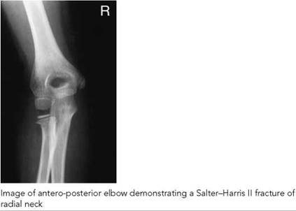
Common faults and remedies
• Suboptimal view of the humerus and radial head due to the child being unable to extend the elbow and radiograph being taken with point of elbow balanced on the cassette. See above for how to avoid this.
• If the child is unable to extend the elbow, or if the elbow is flexed in a plaster cast, initially the humerus should be placed parallel to the cassette to best demonstrate a supracondylar fracture. If in acute trauma no fracture is evident on this radiograph, then a repeat image is acquired with the forearm parallel to the cassette to demonstrate the proximal radius and ulna.
• Forearm pronated instead of correct supination.
• Rotated joint. The joints of the shoulder, elbow and wrist should be in the same plane to obtain best positioning.
Essential image characteristics
Antero-posterior projection of elbow:
• Distal end of humerus should be straight, with no rotation or foreshortening.
• Radius and ulna should be parallel and aligned with the humerus, allowing for the carrying angle.
• Radial head should not overlap the capitellum.
• Coning should include distal thirds of the humerus and proximal thirds of the radius and ulna.
• Cortex and trabecular structures should be visually sharp.
• Reproduction of muscle/fat planes.
Lateral projection of elbow:
• Humerus should be in true lateral position, with superimposition of the condyles.
• Humerus should be at right-angles to the radius and ulna.
• Coning should include distal third of humerus and proximal thirds of radius and ulna.
• Soft tissue detail should include the coronoid and olecranon fat pads if displaced.
• Cortex and trabecular structures should be visually sharp.
• Reproduction of muscle/fat planes.
Radiological considerations
• A good knowledge of ossification centres around the elbow is required, with suitable texts (e.g. Keats and Anderson 2001) being available to avoid the necessity for comparison views.
• The radio-capitellar line should pass through the radius and mid-capitellum on both projections.
• The anterior humeral line should pass through the anterior third of the capitellum on the lateral projection.
• The ossification centres appear in order of the pneumonic CRITOE (capitellum, radius, internal epicondyle, trochlea, olecranon and external epicondyle).


Child positioned for dorsi-palmar projection of a non-dominant hand

Image of a postero-anterior hand in an 18-month-old child with cystinosis and rickets who has delayed bone age of 6 months (G&P)

Recommended projections
There are two main methods of bone age assessment: atlas matching by Greulich and Pyle (Greulich and Pyle 1959) and the point scoring system by Tanner and Whitehouse (Tanner et al. 1983). Slightly different results are produced and the same method should be used for serial measurements.
The non-dominant hand should be selected.
The protocol requires a dorsi-palmar projection of the whole hand, including all digits and the wrist joint.
The fingers should be straight, with the metaphyses in profile.
Radiography of the dorsi-palmar projection of the hand is described on p. 40.
The determination of osseous maturation is based on the number, size and appearance of the ossification centres and on the width of the growth plate or the degree of fusion present.
Radiological considerations
Girls are more advanced than boys, and separate standards are available. Nineteen of 20 children are within two standard deviations (SDs) from the mean of their chronological age. The SDs vary with age, and any assessment of bone age should include the degree of deviation from the mean and value of one SD at that age.
If there are no ossification centres visible in the carpus, then an antero-posterior of the knee can be taken to demonstrate the presence of the distal femoral and proximal tibial ossification centres, which appear at 36 and 37 weeks, respectively.
Children with retarded or advanced bone ages may be short or tall for their age. Children with advanced bone age may undergo premature fusion of the epiphyses and be short in adult life. A predicted adult height can be obtained from standard tables, which require an assessment of current height and bone age.
Bone age is normally required in patients suspected of having an underlying endocrine abnormality and is commonly requested in patients with precocious puberty. A bone age is also performed in patients with suspected significant nutritional deficiency, chronic disease and possible underlying syndrome. Occasionally, the diagnosis of a syndrome can be inferred from the hand radiograph, e.g. Turner's syndrome, with such patients having short fourth and fifth metacarpals.
Image of a hand in a child of 6 years and 10 months with growth hormone deficiency and a dissociated bone age. The phalangeal bone age is 5 years and the carpal bone age is 2 years (G&P)
Feet - supported/ weight-bearing projections
Radiographic examination of the feet, with the child standing
weight-bearing, is undertaken in the assessment of:
• talipes (congenital foot deformity present at birth);
• painful flat foot.
Recommended projections
Examination of the affected foot is undertaken for both babies
and toddlers using the following projections:
Basic Dorsi-plantar (antero-posterior) - weight-bearing
Lateral - weight-bearing
Supplementary Lateral - with forced dorsiflexion
Dorsi-plantar oblique
Dorsi-plantar - weight-bearing
A cassette is selected that is large enough to include the foot.
Position of patient and cassette
Babies
• The baby is supported supine on the X-ray table, and the knee of the affected side is flexed so that the foot rests on the cassette.
• The foot is adjusted so that the tibia is perpendicular to the cassette.
• Both feet may be examined together, with the knees held together.
• Pressure should be applied to the bent knee to simulate weight-bearing.
Toddlers
• The toddler is seated in a special seat, with both feet resting on the cassette in a similar way as that described above. Or, if the child is old enough, they adopt a standing position.
• Downward pressure is applied to both knees.
• No attempt should be made to correct alignment of forefeet.
Direction and centring of the X-ray beam
• The vertical central ray is directed midway between the malleoli and at right-angles to an imaginary line joining the malleoli.
• The central ray may be angled five to 10 degrees cephalic to avoid the tibiae overlapping the hind feet.
Essential image characteristics
• The alignment of the talus and calcaneus of the hind foot should be clearly visible, with no overlapping by the shins.
• Visualization of the bones of the feet consistent with age.
• Visualization of the soft tissue planes.
• Reproduction of the spongiosa and cortex.

Baby positioned for dorsi-plantar projection of feet with feet support

Image of dorsi-plantar feet in a baby with talipes equinovarus. Note calcaneus and talus are parallel and superimposed

Left: older child positioned for weight-bearing, dorsi-plantar projection of feet. Note the slight posterior lean to avoid the long bones overlying and obscuring the hind feet. Right: image of 4-year-old boy's foot with corrected CTEV and residual varus of the forefoot

Baby positioned for lateral projection of foot with pressure applied by a wood block support in order to try and correct any equinus deformity of the ankle

Image of lateral foot in neonate and older child with talipes equinovarus demonstrating talus and calcaneus parallel in former and dorsal dislocation of navicular in the corrected foot of the latter
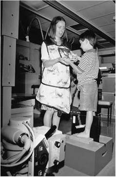
Phototograph of older child standing for a lateral projection of the foot
Lateral - weight bearing
A cassette is selected that is large enough to include the foot.
Position of patient and cassette
Babies
• With the baby supine on the imaging couch, the affected leg is preferably internally rotated so that the inner border of the foot is placed against the cassette with the ankle (not forefoot) in the true lateral position. Alternatively, the leg is externally rotated, with the lateral aspect of the foot against the cassette.
• A wooden block support is positioned beneath the sole of the foot, with dorsiflexion pressure applied during exposure to demonstrate the reducibility of any equinus deformity at the ankle.
Toddlers
• The child can be examined standing, with a cassette placed in a groove against the inner foot.
• To stop the foot from being inverted, the leg should not be externally rotated.
• Forced dorsi-/plantarflexion views may also be required.
Direction and centring of the X-ray beam
• The central ray is directed to the lateral/medial malleolus at right-angles to the axis of the tibia. For toddlers, the beam is directed horizontally.
Essential image characteristics
• The alignment of the talus and calcaneus in the true lateral position should be clearly visible.
• The sole of the foot should be flat against the block, with no elevation of the heel.
• See dorsi-plantar projection characteristics, above.
Common faults and remedies

Image of lateral foot of a child hind foot valgus and almost vertical talus in a patient with cerebral palsy
• For the dorsi-plantar projection, the shins often obscure the hind feet. Angle the beam 10 degrees cephalad to overcome this problem.
• The density of the image (dorsi-plantar) is correctly appropriate for forefeet but does not demonstrate the hind-foot, which is more important. A wedge can be used to avoid overpenetration of the forefeet.
• For the lateral projection, care should be taken to avoid oblique projection of the foot as this could simulate a valgus/varus position.
Radiological considerations
Foot radiographs should allow correct assessment of the alignment of the bones of the hindfoot, midfoot and forefoot. Various terminology is used to describe their position.
The term talipes originates in an old description of a patient walking on his ankle (talus) rather than the foot (pes). The terms calcaneus and equinus refer to the position of the foot in relation to the ankle. The former indicates dorsiflexion with elevation of the anterior end of the calcaneum and equinus indicates plantarflexion of the calcaneum like a horse's foot
Hindfoot varus
Hindfoot varus means that an axial reference line through the calcaneum is deviated towards the midline of the body. The degree of varus angulation is determined by measurement of the talo-calcaneal angle on an antero-posterior projection, which will be decreased leading to parallelism and overlapping of the talus and the calcaneus. The long axis of the talus (midtalar line) passes lateral to the base of the first metatarsal and the talus and calcaneus are also parallel on the lateral view.
Hindfoot valgus
Hindfoot valgus means that an axial reference line though the calcaneum is deviated away from the midline of the body. The talo-calcaneal angle on an antero-posterior projection of the foot will be increased and similarly on the lateral projection, leading to a more vertical talus.
The talo-calcaneal angles vary with age and should be compared with recognized tables (Keats and Sistrom, 2001). However, it is to be noted that calculated angles are not always abnormal in abnormal feet.
Lateral radiographs allow assessment of the plantar arch. Increased height of the arch (cavum arch) is associated with valgus/varus foot deformities. A flattened arch (pes planus) may be due to a flexible flat foot, tarsal coalition or other congenital conditions.
Congenital talipes equinovarus (CTEV or club foot) is the most common abnormality. This consists of hindfoot equinus, hind- foot varus and forefoot varus. It occurs in 1-4/1000 live births, males being more commonly affected, it is usually idiopathic and there is a slight genetic preponderance.
Congenital talipes calcaneus is a common neonatal condition which normally corrects spontaneously but those with valgus of the calcaneum may have underlying hip dislocation.

Dorsi-plantar oblique image of a right foot demonstrating calcaneo-navicular coalition
Congenital vertical talus produces a more severe valgus deformity. Eighty percent are associated with syndromes or CNS disorders. The vertical talus and equinus of the calcaneum produce a convex plantar arch (rocker bottom foot).
Metatarsus adductus, which should be distinguished from CTEV, has a normal hindfoot with adduction of the forefoot and most correct with passive reduction.
Tarsal coalition
If a tarsal coalition is suspected because of a painful flat foot, evidence of talar beaking should be sought on the lateral image, which may be due to talo-calcaneal fusion, for which CT is required for confirmation. A dorsi-plantar oblique (45 degrees) projection of the foot is necessary for the demonstration of a calcaneo-navicular coalition. Both forms of coalition can be fibrous/osseous.
Note
Foot deformities need careful positioning, and analysis of the derangement and care must be taken to produce high-quality radiographs. Radiographs should be performed weight-bearing or with stressed dorsiflexion in order to appreciate the true alignment and to determine the degree of unreducable equinus in patients with CTEV.
Examples of various foot derangements are shown overleaf.

Neonate - right dorsi-plantar calcaneovalgus right foot

Neonate - lateral foot with calcaneovalgus and vertical talus


Recumbant image of lateral foot demonstrating pes cavus in a patient with cerebral palsy

Recumbant lateral foot showing severe planus valgus and a vertical talus in a patient with a meningomyelocele
Skeletal survey for non-accidental injury
Occult bony injury is rare over three years of age, and most NAI surveys are performed on infants under two years of age. They are also indicated in siblings under two years of age when the index case is proven NAI.
A skeletal survey is the main radiological investigation for NAI. It comprises a series of images taken to assess the whole skeleton.
Evidence of NAI to children is an all too common occurrence in any department dealing routinely with children. It can result in serious long-term emotional and physical injuries. The latter include serious neurological deficits, mental retardation and in, the worst cases, death of the child.
Certain skeletal injuries in this condition are highly suspicious. Posterior rib fractures (Kleinman and Schlesinger 1997) and metaphyseal fractures are almost pathognomonic of NAI. Carefully evaluated, well-collimated, high-detail, skeletal radiographs are vital in all cases of suspected infant abuse (Carty 1997, Kleinman and Marks 1992, Nimkin and Kleinman 1997, Nimkin et al. 1997).
Rationale for projections
A skeletal survey is needed to demonstrate pathology, but it is equally important in dating skeletal injuries, as accurate evaluation and dating of these injuries will be vital in providing legal argument (Kleinman et al. 1989). This may require further views of certain specific areas, and this has to be tailored to the appearances of the initial injuries and to the clinical history given (Kleinman et al. 1996).
Post-mortem skeletal studies may also be required in some cases and can provide useful additional information (Thomsen et al. 1997).
It is rarely, if ever, necessary for a skeletal survey to be performed by junior staff outside normal hours (see radiological considerations).
Referral criteria
The referral criteria that would justify a skeletal survey are as follows:
Projections
The projections advised below are suggested by the RCR (British Society of Paediatric Radiologists, BSPR). Fifty per cent of rib fractures are occult, compared with 20% of limb fractures, and as they are diagnostically important, oblique rib projections are justified. Oblique views of the hands are preferred as they are more likely to show buckle and subtle cortical fractures (Nimkin et al. 1997).
The advised projections are as follows:
• antero-posterior chest (chest to show all ribs, clavicles and shoulders);
• abdomen (to include pelvis);
• antero-posterior right and left femur (to include hip and knee joints and upper two-thirds of tibia and fibula);
• antero-posterior right and left ankle (to include distal third of tibia and fibula);
• antero-posterior right and left humerus;
• antero-posterior right and left forearm;
• lateral cervical, thoracic and lumbar spines;
• antero-posterior skull, lateral skull (and Towne's if occipital fracture suspected);
• oblique ribs (may be delayed by up to 10 days);
• anterior oblique of both hands;
• antero-posterior both feet;
• coned/lateral views of fractures or abnormalities.
The practice of imaging the entire body on one radiograph 'babygram' should never be performed. This is a totally inadequate and uninterpretable examination. Two healthcare personnel should always be present in the room for the examination, e.g. radiographer and nurse. Both should sign the radiograph and request form, and the timing of the examination should be recorded accurately. This is important for legal documentation. In the case of digital imaging and electronic request forms, a signed record should be made in the patient's notes.
Current recommendations are that a CT of the head should routinely be performed under one year of age and with a very low threshold for those under two years of age, to exclude associated subdural collections.
Radiological considerations
A high index of suspicion is required. However, a skeletal survey should be requested only following discussion between the consultant paediatrician and consultant radiologist, as the radiation dose from an inappropriate skeletal survey should be avoided and is just as much a reason for litigation as failure to identify fractures. It requires radiologist involvement to ensure diagnostic quality, to allow additional projections of any injury to be taken, and to suggest the timing of any repeat studies. The outcome, whether positive or negative, may have huge implications (for the family especially). Good clinico-radiological cooperation at the highest level is vital, supported by the highest standard of radiography.


Antero-posterior chest showing bilateral anterior rib fractures

Antero-posterior skull showing right parietal fracture

Image of lateral skull showing biparietal fractures

Antero-posterior left upper limb, shoulder to wrist, demonstrating spiral fracture of the humerus
Radiation protection
Well-collimated, carefully positioned images provide not only a far higher quality but also a lower radiation dose. Higher-kVp techniques with additional filtration are usually recommended as dose-saving measures in paediatrics. However, in an NAI survey, low kVp/high mAs should be employed for best demonstration of bony detail and soft tissues. It may be advised to avoid additional filtration (inherent of approximately 2.5 mm aluminium) because it will have the most detrimental effect on image quality when low-kVp techniques are used.
Radiographic technique
Well-tried and tested restraining methods are most important in performing skeletal surveys to ensure high quality.
A patient, careful, non-judgemental approach is essential, and full explanation should have been given to the parents by the requesting clinician. Patient positioning and X-ray beam centring has already been described for the individual examinations, but there are some differences in technique, which are outlined below.
Chest/abdomen
• Shoulders and all ribs should be included on the image.
• A minimum of 400-speed class film/screen system is used to reduce movement unsharpness.
• The tube potential should be between 60 and 70kVp to ensure optimum bony detail.
Spine (cervical, thoracic and lumbar)
• A minimum of 400-speed class film/screen system is used to reduce movement unsharpness.
• A single lateral image is acquired without the use of a grid in children under three years of age.
• Tube potential up to 70kVp.
Skull
• The antero-posterior and lateral images are acquired without the use of a grid if the child is under one year of age.
• The lateral image is acquired using a lateral horizontal beam.
• Tube potential up to 70 kVp.
Upper and lower limbs
• A 200-speed class film/screen system and 45-60-kVp range is used to provide optimum soft tissue and bony detail.
• Separate images of the humerus and radius and ulna are normally acquired after 18 months of age.
• Separate images of the femur and tibia and fibula are acquired. The image of the femur should include the knee joint.
• May need adhesive tape ruler/strapping for restraint (see p. 430).
Common faults and remedies
• Views of epiphyses and metaphyses in profile are needed to show the classical metaphyseal fractures as corner fractures. The actual fracture occurs right across the metaphysis. If the radiographic beam is divergent or the metaphyses are tilted, then the fracture appears as a bucket-handle fracture, but this can easily be missed or thought to be due to a normal variation in the appearance of the ossification of the meta- physes. Correct interpretation needs precise technique.
• An attempt to radiograph the whole leg together should be avoided. Immobilization can be provided only at the feet, and excessive plantarflexion whilst holding can result in tilted metaphyses and the heels obscuring the ankle joints.
Essential image characteristics
• These are as described for the individual anatomical areas. Extremely good-quality radiographs are essential, with excellent bone and soft tissue detail.


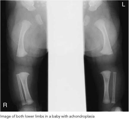

Skeletal survey for syndrome
assessment
A similar technique can be used for syndrome assessment.
The radiographs performed will depend on the suspected syndrome or clinically visible abnormalities. However, a syndrome skeletal survey will normally include:
• antero-posterior skull;
• lateral skull;
• postero-anterior/antero-posterior chest;
• antero-posterior whole spine;
• lateral whole spine;
• pelvis;
• antero-posterior both whole legs, separately or together on one image depending on ease of handling;
• postero-anterior of non-dominant hand for bone age.
Notes
• Additional radiographs of the upper limbs, hand and feet can be performed if there is clinical deformity.
• Lateral projections may be required for bowed limbs.


Acknowledgements
We would like to thank Mrs Wendy Appleby and Mrs Jane Radford for their much-valued support in the typing and layout of the text. We would also like to thank Mr M Fitzgerald, Mr J Kyriou and Mrs A Pettet (Radiological Protection Centre, St George's Hospital, London) and Dr S M Pablot and Dr Mary Warren (Queen Mary's Hospital for Children, Epsom and St Helier University NHS Trust, Carshalton, Surrey) for their respected and extremely useful comments, encouragement and honest opinion. Also Mr Robert Wade and the Medical Illustration Department at Queen Mary's Hospital for Children for their much appreciated attention given to providing most of the illustrations.
We are also very grateful to the Medical Engineering Research Unit (MERU) at QMHC for their assistance and skills in producing the immobilization device with Perspex top and wooden cassette holder, the chest stand with seat and the various shaped coning devices and filters described in the text. They have all been designed by Kaye Shah and the staff of QMHC.
Further acknowledgements
We would also like to express our sincere thanks to Stewart Whitley and all the members of staff of Blackpool Victoria Hospital and Alder Hey Hospital, Liverpool, for the contributions on the Denton skull radiography technique and alternative techniques for the leg lengthening.
References
Almen A, Loof M, Mattsson S (1996). Examination technique, image quality, and patient dose in paediatric radiology. A survey including 19 Swedish hospitals. Acta Radiol 37(3 Part 1): 337-42.
Andersen PE Jr, Andersen PE, van der Kooy P (1982). Dose reduction in radiography of the spine in scoliosis. Acta Radiol 23:251-3.
Arena L, Baker SR (1990). Use of a metal detector to identify ingested metallic foreign bodies. Am J Roentgenol 155:803-4.
Boulis ZF, Dick R, Barnes NR (1978). Head injuries in children - aetiology, symptoms, physical findings and x ray wastage. Br J Radiol 51:851-4.
Carty H (1997). Non-accidental injury: a review of the radiology. Eur Radiol 7:1365-76.
Cook JV, Shah K, Pablot S, Kyriou J, Pettet A, Fitzgerald M. (1998). Guidelines on Best Practice in the X Ray Imaging of Children. London: Queen Mary's Hospital for Children, Epsom and St Helier University NHS Trust and Radiological Protection Centre, St George's Hospital.
Denton BK (1998). Improving plain radiography of the skull: the half-axial projection re-described. Synergy August, pp. 9-11.
Dhar S, Dangerfield PH, Dorgan JC, Klenerman L (1993). Correlation between bone age and Risser's sign in adolescent idiopathic scoliosis. Spine 18:14-19.
European Commission (1996). European Guidelines on Quality Criteria for Diagnostic Radiographic Images in Paediatrics. Luxembourg: Office for Official Publications of the European Communities. (Available from HMSO Books, London.)
Garniak A, Feivel M, Hertz M, Tadmor R (1986). Skull X-rays in head trauma: are they still necessary? A review of 1000 cases. Eur J Radiol 6:89-91.
Greulich WW, Pyle SI (1959). Radiographic Atlas of Skeletal Development of the Hand and Wrist. Stanford, CA: Stanford University Press.
Hansson B, Finnbogason T, Schuwert P, Persliden J (1997). Added copper filtration in digital paediatric double-contrast colon examinations: effects on radiation dose and image quality. Eur Radiol 7:1117-22.
Hart D, Wall BF, Shrimpton PC, Bungay DR, Dance DR (2000). Reference Doses and Patient Size in Paediatric Radiology. Chilton: National Radiological Protection Board.
Hilton SvW, Edwards DK (1994). Practical Paediatric Radiology. Philadelphia: W.B. Saunders.
Hochschild TJ, Cremin BJ (1975). Technique in infant chest radiography. Radiography Jan 41(481):21-5.
Hufton AP, Doyle SM, Carty HM (1998). Digital radiography in paediatrics: radiation dose considerations and magnitude of possible dose reduction. Br J Radiol 71:186-99.
Ilizarov GA (1988) The principles of the Ilizarov method. Bull Hospital Joint Dis Orthop Inst Spring 48(1):1-11.
Institute of Physics and Engineering in Medicine (2004). IPEM Report 88 Guidance on the Establishment of Diagnostic Reference Levels for Medical X ray Examination. York: IPEM.
Jonsson A, Jonsson K, Eklund K, Holje G, Pettersson H (1995). Computed radiography in scoliosis. Diagnostic information and radiation dose. Acta Radiol 26:429-33.
Keats TE, Anderson MW (2001). Atlas of Normal Roentgen Variants that May Simulate Disease 7th edn. St Louis, MO: Mosby.
Keats TE, Sistrom C (2001). Atlas of Radiologic Measurement 7th edn. St Louis, MO: Mosby.
Kleinman PK, Marks SC (1992). Vertebral body fractures in child abuse. Radiologic-histopathological correlates. Invest Radiol 27:715-22.
Kleinman PK, Schlesinger AE (1997). Mechanical factors associated with posterior rib fractures: laboratory and case studies. Pediatr Radiol 27:87-91.
Kleinman PK, Blackbourne BD, Marks SC, Karellas A, Belanger PL (1989). Radiologic contributions to the investigation and prosecution of cases of fatal infant abuse. N Engl J Med 320:507-11.
Kleinman PK, Nimkin K, Spevak MR, Rayder SM, Madansky DL, Shelton YA, Patterson MM (1996). Follow-up skeletal surveys in suspected child abuse. Am J Roentgenol 167:893-6.
Kottamasu SR, Kuhns LR (1997). Musculoskeletal computed radiography in children: scatter reduction and improvement in bony trabecular sharpness using air gap placement of the imaging plate. Pediatr Radiol 27:119-23.
Kyriou JC, Fitzgerald M, Pettet A, Cook JV, Pablot SM (1996). A comparison of doses and techniques between specialist and non-specialist centres in the diagnostic X-ray imaging of children. Br J Radiol 69:437-50.
Lloyd DA, Carty H, Patterson M, Butcher CK, Roe D (1997). Predictive value of skull radiography for intracranial injury in children with blunt head injury. Lancet 349:821-4.
Lowe A, Finch A, Boniface D, Chaudhuri R, Shekhdar J (1999). Diagnostic image quality of mobile neonatal chest x-rays and the radiation exposure incurred. Br J Radiol 72:55-61.
Marshall NW, Faulkner K, Busch HP, March DM, Pfenning H (1994). A comparison of radiation dose in examination of the abdomen using different radiological imaging techniques. Br J Radiol 67:478-84.
Masters SJ, McClean PM, Arcarese JS et al. (1987). Skull X-ray examinations after head trauma. Recommendations by a multi disciplinary panel and validation study. N Engl J Med 316:84-91.
McDaniel DL, Cohen G, Wagner LK, Robinson LH (1984). Relative dose efficiencies of antiscatter grids and air gaps in paediatric radiography. Med Phys 11:508-12.
McDonald S, Martin CJ, Darragh CL, Graham DT (1996). Dose-area product measurements in paediatric radiography. Br J Radiol 69:318-25.
McParland BJ, Gorka W, Lee R, Lewall DB, Omojola MF (1996). Radiology in the neonatal intensive care unit: dose reduction and image quality. Br J Radiol 69:929-37.
Mooney R, Thomas PS (1998). Dose reduction in a paediatric x-ray department following optimization of radiographic technique. Br J Radiol 71:852-60.
Nimkin K, Kleinman PK (1997). Imaging of child abuse. Pediatr Clin North Am 44:615-35.
Nimkin K, Spevak MR, Kleinman PK (1997). Fractures of the hands and feet in child abuse: imaging and pathologic features. Radiology 203:233-6.
Rosenbaum AE, Arnold BA (1978). Postero-anterior radiography: a method for reduction of eye dose. Radiology 129:812.
Royal College of Radiologists (2003). Making the Best Use of a Department of Clinical Radiology, 5th edn. London: Royal College of Radiologists.
Ryan J, Tidey B (1994). Metal detectors to detect aluminium. Br Med J 309:131.
Ruiz MJ, Gonzalez L, Vano E, Martinez A (1991). Measurement of radiation doses in the most frequent simple examinations in paediatric radiology and its dependence on patient age. Br J Radiol 64:929-33.
Thomsen TK, Elle B, Thomsen JL (1997). Post mortem examination in infants: evidence of child abuse? Forensic Sci Int 90:223-30.
Tanner JM, Whitehouse RH, Cameron N, Marshall WA, Healy MJR, Goldstein H (1983). Assessment of Skeletal Maturity and Prediction of Height 2nd edn. London: Academic Press.
United Nations Scientific Committee on the Effects of Atomic Radiation (2000). Unscear Report: Sources and Effects of Ionizing Radiation Vol. II. Vienna: United Nations Scientific Committee on the Effects of Atomic Radiation.
Vano E, Oliete S, Gonzalez L, Guibelalde E, Velasco A, Fernandez JM (1995). Image quality and dose in lumbar spine examinations: results of a 5 year quality control programme following the European quality criteria trial. Br J Radiol 68:1332-5.
Warren-Forward HM, Millar JS (1995). Optimization of radiographic technique for chest radiography. Br J Radiol 68:1221-9.
Wraith CM, Martin CJ, Stockdale EJ, McDonald S, Farquhar B (1995). An investigation into techniques for reducing doses from neo-natal radiographic examinations. Br J Radiol 68:1074-82.