Introduction
Radiographic examinations of the shoulder joint and shoulder girdle can be carried out with the patient supine on the X-ray table or trolley, but in most cases it will be more comfortable for the patient to sit or stand with the back of the shoulder in contact with the cassette. The erect position affords ease of positioning, allows the head of humerus to be assessed more accurately for potential impingement syndrome, and can sometimes demonstrate a lipohaemarthrosis where there is a subtle intra-articular fracture.
For radiation protection, particularly of the eyes, the patient's head should be rotated away from the side being examined.
The central ray can be directed caudally after centring to the coracoid process so that the primary beam can be collimated to the area under examination.
For a general survey of the shoulder, e.g. for injury, the field size must be large enough to cover the whole of the shoulder girdle on the injured side. When localized areas are being examined, however, e.g. tendon calcifications or joint spaces, the X-ray beam should be well collimated.
To improve radiographic contrast, a secondary radiation grid can be used for large patients; however, the increased contrast resolution of a computed radiography (CR) imaging system reduces the need for this.
When examining the shoulder joint, it is important to check on the position of the head of the humerus by palpating and positioning the epicondyles at the distal end of the humerus. When the line joining the epicondyles is parallel to the tabletop (or vertical cassette), the humerus is in position for an antero-posterior projection of the head of the humerus. To judge the degree of rotation of the humerus by the position of the hand can be very misleading.
The image appearance is affected significantly by the posture of the patient. If the patient leans back into the cassette, adopting a lordotic stance, then the head of humerus will overlie the acromion process. Conversely, if the patient leans forward, the head of humerus becomes projected inferiorly, appearing to be subluxated.
As in all other skeletal examinations, radiographs showing good bone detail are required to demonstrate minor fractures and bone changes associated with pathology, including injuries to tendon insertions.
Radiological considerations
The rounded humeral head articulates with a rather flat glenoid to maximize the possible range of movement at the joint. The stability of the joint is maintained by the cartilage of the glenoid labrum, ligaments, and the tendons of the rotator cuff. The rotator cuff is four broad tendons encircling the glenohumeral joint. The most superior of these is the supraspinatus, which traverses the subacromial tunnel between the undersurface of the acromion and the upper surface of the humerus to reach its insertion.
Impingement is a common orthopaedic problem occurring when the subacromial space is compromised by degenerative disease, often exacerbated by congenital anomalies of the acromion. The tendon of supraspinatus then becomes compressed between the humerus and the acromion, causing mechanical pain, tendinitis and tendon tears. Radiological signs are non-specific, but radiographs help to assess the width of the subacromial space and the shape of the acromion. It is important that projections of the shoulder in patients with suspected impingement show the subacromial space adequately. Rotation of the patient or incorrect angulation of the beam can obscure the signs.
Tendinitis (inflammation) may cause visible calcification and is seen most frequently in the supraspinatus tendon on a good antero-posterior (AP) projection, although an outlet projection may be a useful addition. The calcification can be obscured by poor technique.
In the various forms of arthritis, the glenohumeral articulation is primarily affected. The width of this joint space is a marker of the severity and progression of disease, and obtaining a projection along the joint line is therefore crucial.
Posterior dislocation is uncommon. Signs on the AP image may be no more than subtle loss of the normal congruity between the glenoid and humeral articular surfaces; therefore, if this is suspected, an axial projection is particularly important.
Detailed examination of the entire shoulder mechanism would require multiple projections. The practitioner must therefore be familiar with the reasons for examination to ensure selection of the appropriate projections to address the clinical problem.
Ultrasound in experienced hands is a valuable tool for assessment of the shoulder, especially for rotator cuff tears. It may be more sensitive than plain radiography for some calcifications. It is often easier to obtain than magnetic resonance imaging (MRI), although it cannot image the glenohumeral joint.
MRI can show all the joint structures, including the rotator cuff, and will be required if there is concern regarding areas not seen well on ultrasound, if ultrasound is equivocal, or if ultrasound expertise is not available.
Unenhanced computed tomography (CT) has a role in assessing the severity of complex fractures around the shoulder.
For recurrent dislocations, accurate imaging of the bony glenoid and labrum, the capsule and glenohumeral ligaments, as well as the rotator cuff is needed. Cross-sectional imaging (MRI or CT) with arthrography is often required.
Recommended projections
Basic projections
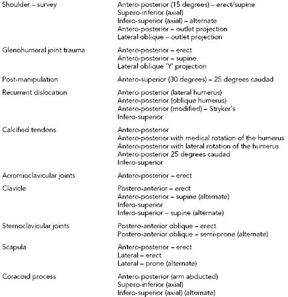
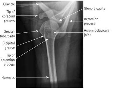
It is common practice to obtain two views of the shoulder joint, particularly in cases of suspected dislocation: an antero-posterior (supine) view using a 24 X 30-cm cassette and a supero-inferior (axial) view using an 18 X 24-cm cassette. An avulsion fracture of the greater tuberosity is often seen only on the axial projection.
Modified projections may be undertaken to demonstrate the anterior portion of the acromion process in cases of suspected shoulder impingement syndrome.
These projections may be undertaken with the patient seated or standing, provided that adequate immobilization is used.
If the patient is obese, then the use of a grid cassette or Bucky may improve the contrast of the image but will result in an increased radiation dose.

Position of patient and cassette
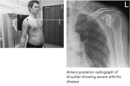
• The patient stands with the affected shoulder against the cassette and is rotated 15 degrees to bring the shoulder closer to the cassette and the plane of the acromioclavicular joint parallel to the central beam.
Basic projections 3
Antero-posterior (15 degrees) erect - survey image
• The arm is supinated and slightly abducted away from the body. The medial and lateral epicondyles of the distal humerus should be parallel to the cassette.
• The cassette is positioned so that its upper border is at least 5 cm above the shoulder to ensure that the oblique rays do not project the shoulder off the cassette.
Direction and centring of the X-ray beam
• The horizontal central ray is directed to the palpable coracoid process of the scapula. The beam can then be directed caudally and collimated.
• The central ray passes through the upper glenoid space to separate the articular surface of the humerus from the acromion process.
Essential image characteristics
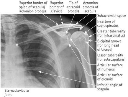
• The image should demonstrate the head and proximal end of the humerus, the inferior angle of the scapula and the whole of the clavicle.
• The head of the humerus should be seen slightly overlapping the glenoid cavity but separate from the acromion process.
• Arrested respiration aids good rib detail in acute trauma.
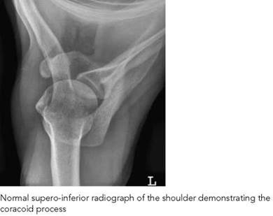
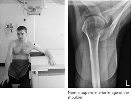
Supero-inferior (axial)
Position of patient and cassette
• The patient is seated at the side of the table, which is lowered to waist level.
• The cassette is placed on the tabletop, and the arm under examination is abducted over the cassette.
• The patient leans towards the table to reduce the object-to- film distance (OFD) and to ensure that the glenoid cavity is included in the image. A curved cassette, if available, can be used to reduce the OFD.
• The elbow can remain flexed, but the arm should be abducted to a minimum of 45 degrees, injury permitting. If only limited abduction is possible, the cassette may be supported on pads to reduce the OFD.
Direction and centring of the X-ray beam
• The vertical central ray is directed through the proximal aspect head of the humeral head. Some tube angulation, towards the palm of the hand, may be necessary to coincide with the plane of the glenoid cavity.
• If there is a large OFD, it may be necessary to increase the overall focus-to-film distance (FFD) to reduce magnification.
Infero-superior (alternate)
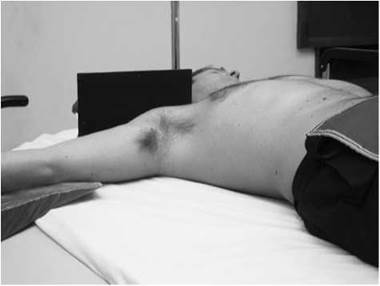
This projection may be used as an alternative to the supero- inferior projection in cases of dislocation or when the patient is supine, since it can be taken even when the patient is able to abduct the arm only slightly. No attempt should be made to increase the amount of abduction that the patient is able and willing to make. An 18 X 24-cm cassette is used.
Position of patient and cassette
• The patient lies supine, with the arm of the affected side slightly abducted and supinated without causing discomfort to the patient.
• The affected shoulder and arm are raised on non-opaque pads.
• A cassette is supported vertically against the shoulder and is pressed against the neck to include as much as possible of the scapula on the film.
Direction and centring of the X-ray beam
• The horizontal central ray is directed towards the axilla with minimum angulation towards the trunk.
• The FFD will probably need to be increased, since the tube head will have to be positioned below the end of the trolley.
Essential image characteristics
• The image should demonstrate the head of the humerus, the acromion process, the coracoid process and the glenoid cavity of the scapula.
• The lesser tuberosity will be in profile, and the acromion process and the superior aspect of the glenoid will be seen superimposed on the head of humerus.
Note
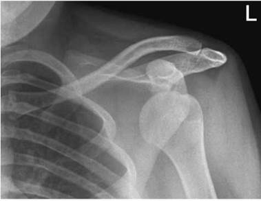
The most common type of dislocation of the shoulder is an anterior dislocation, where the head of the humerus displaces below the coracoid process, anterior to the glenoid cavity. Much rarer is a posterior dislocation. In some instances, although the antero-posterior projection shows little or no evidence of a posterior dislocation, it can always be demonstrated in an infero- superior or supero-inferior projection of the shoulder.
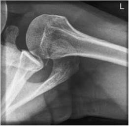
Normal infero-superior radiograph of the shoulder
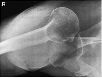
Axial radiograph of the shoulder showing posterior dislocation
Outlet projections
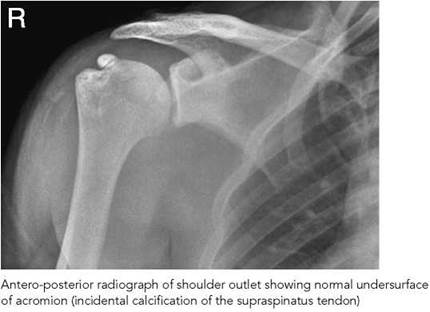
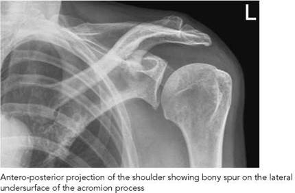
In cases of suspected shoulder impingement syndrome, it is important to visualize the anterior portion of the acromion process. Routine projections described above are frequently unsatisfactory because the anterior portion of the acromion is superimposed on the body of the acromion. If the antero-posterior projection is undertaken with the X-ray beam angled 30 degrees caudally, the anterior part of the acromion is projected inferiorly to the body of the acromion and is visualized more clearly.
A modified lateral projection (outlet view) with 10-degree caudal angulation may also be undertaken.
Antero-posterior (outlet projection)
Position of patient and cassette (as for the antero-posterior survey image)
• The patient stands with the affected shoulder against a cassette and is rotated 15 degrees to bring the plane of the scapula parallel with the cassette.
• The arm is supinated and slightly abducted away from the body. The medial and lateral epicondyles of the distal humerus should be parallel to the cassette.
• The cassette is positioned so that its upper border is at least 5 cm above the shoulder to ensure that the oblique rays do not project the shoulder off the cassette.
Direction and centring of the X-ray beam
• The horizontal central ray is directed 30 degrees caudally and centred to the palpable coracoid process of the scapula.
• An 18 X 24-cm cassette is used with the beam collimated to the glenohumeral joint.
Essential image characteristics
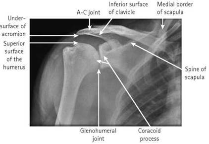
• The image should demonstrate the anterior part of the acromion projected inferiorly to the body to visualize the presence of bony spurs or abnormally long acromion process.
• The subacromial joint space should be shown above the humeral head.
Lateral (outlet projection)
Position of patient and cassette
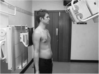
• The patient stands or sits facing the cassette, with the lateral aspect of the affected arm in contact.
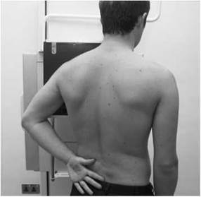
• The affected arm is extended backwards, with the dorsum of the hand resting on the patient’s waist.
• The patient is adjusted so that the head of the humerus (coracoid process) is in the centre of the cassette.
• The patient is now rotated forward until a line joining the medial and lateral borders of the affected scapula is at right-angles to the cassette. The body of the scapula is now at right-angles to the cassette, and the scapula and the proximal end of the humerus are clear of the rib cage.
Direction and centring of the X-ray beam
• The horizontal central ray is angled 10 degrees caudally and centred to the head of the humerus.
• The beam is collimated to an 18 X 24-cm cassette.
Essential image characteristics
• The image should demonstrate the extent of the anterior projection of the acromion and the subacromial space.
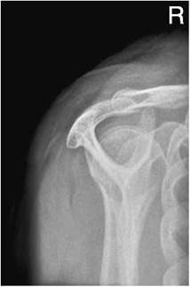
Normal radiograph of lateral shoulder outlet
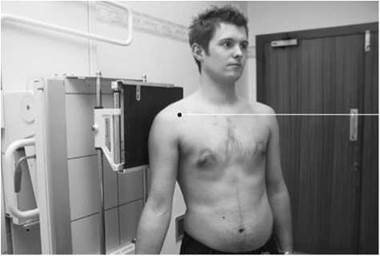
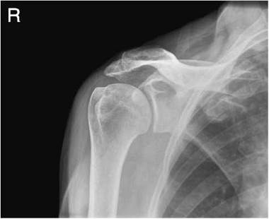
Normal antero-posterior radiograph of the shoulder to show glenohumeral joint
Glenohumeral joint
Antero-posterior - erect
To demonstrate the glenoid cavity and glenohumeral joint space, the body of the scapula should be parallel to the cassette so that the glenoid cavity is at right-angles to the cassette. The horizontal central ray can now pass through the joint space parallel to the glenoid cavity of the scapula.
Position of patient and cassette
• The patient stands with the affected shoulder against the cassette and is rotated approximately 30 degrees to bring the plane of the glenoid fossa perpendicular to the cassette.
• The arm is supinated and slightly abducted away from the body.
• The cassette is positioned so that its upper border is at least 5 cm above the shoulder to ensure that the oblique rays do not project the shoulder off the cassette.
Direction and centring of the X-ray beam
• The horizontal central ray is centred to the palpable coracoid process of the scapula.
• The primary beam is collimated to an 18 X 24-cm cassette.
Essential image characteristics
• The image should demonstrate clearly the joint space between the head of the humerus and the glenoid cavity.
• The image should demonstrate the head, the greater and lesser tuberosities of the humerus, together with the lateral aspect of the scapula and the distal end of the clavicle.
Antero-posterior - supine (trauma)
There are occasions when the patient cannot be examined in the erect position, e.g. due to multiple trauma or immobility. Often, such patients present on a trolley in the emergency situation.
Position of patient and cassette
• The patient lies supine on the trolley, and the unaffected shoulder is raised slightly to bring the scapula on the affected side parallel to the cassette.
• The arm is partially abducted and supinated clear of the trunk.
• The cassette is positioned under the patient so that its upper border is at least 5 cm above the shoulder to ensure that the oblique rays do not project the shoulder off the film. If the patient cannot be moved, then the cassette tray under the trolley can be used.
Direction and centring of the X-ray beam
• The vertical central ray is centred to the palpable coracoid process of the scapula.
• It may be necessary to direct the primary beam caudally in order to project the head of the humerus below the acromion process.
Essential image characteristics
• The subacromial space should be visible.
• The proximal end of the humerus, the lateral aspect of the scapula and the whole of the clavicle need to be included.
• The greater tuberosity will be in profile when the arm is supinated.
• If the arm cannot be supinated, then the head of humerus has the appearance of a ‘lightbulb’ shape.
Lateral oblique 'Y' projection (alternate) dislocation/fracture proximal humerus
If the arm is immobilized and no abduction of the arm is possible, then a lateral oblique ‘Y’ projection is taken using a 24 X 30-cm cassette in an erect cassette holder or vertical Bucky if the patient is particularly large.
Position of patient and cassette
• The patient stands or sits with the lateral aspect of the injured arm against an erect cassette and is adjusted so that the axilla is in the centre of the film.
• The unaffected shoulder is raised to make the angle between the trunk and cassette approximately 60 degrees. A line joining the medial and lateral borders of the scapula is now at right-angles to the cassette.
• The cassette is positioned to include the superior border of the scapula.
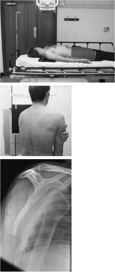
Lateral oblique radiograph of the shoulder showing anterior dislocation
Direction and centring of the X-ray beam
• The horizontal central ray is directed towards the medial border of the scapula and centred to the head of the humerus.
Essential image characteristics
• The body of the scapula should be at right-angles to the cassette, and the scapula and the proximal end of the humerus are clear of the rib cage.
• The exposure should demonstrate the position of the head of the humerus in relation to the glenoid cavity between the coracoid and acromion processes.
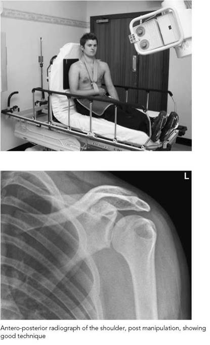
Modifications in technique (post-manipulation)
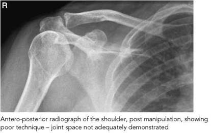
A revised shoulder technique may be necessary immediately following manipulation to check that a shoulder dislocation has been reduced successfully. The affected arm will be immobilized, usually in a collar and cuff support. An image of the joint space is taken in the antero-posterior position on an 18 X 24-cm cassette; this is achieved by raising the unaffected side approximately 30 degrees.
It is important that accurate assessment of the glenohumeral joint is possible from the resultant image in order that an avulsion fracture from around the glenoid rim is demonstrated clearly.
Poor positioning technique may be the result of the following:
• The patient not being X-rayed erect and not enough compensatory caudal angulation being applied.
• The immobilized arm will be nursed with the humerus internally rotated. This has the effect that the coronal plane is often tilted towards the unaffected side.
Such a poor technique results in no joint space being seen, the humeral head overlying the acromion process, and the humeral head appearing as a ‘lightbulb’ with the greater tuberosity not being demonstrated.
Antero-posterior - 25 degrees caudad
Position of patient and cassette
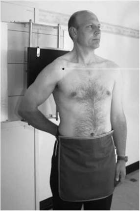
• The patient sits fully erect, if possible, on the accident and emergency (A&E) trolley, with the head section of the trolley raised to a vertical position to support the patient.
• With the arm immobilized in a collar and cuff, the patient is turned 30 degrees towards the affected side.
• The unaffected shoulder is supported on pads to bring the posterior aspect of the affected shoulder into closer contact with the cassette, which is positioned under the affected arm and held in position with the patient’s body weight.
• The cassette is positioned so that its upper border is at least 5 cm above the shoulder to ensure that the oblique rays do not project the shoulder off the film.
Direction and centring of the X-ray beam
• The horizontal central ray is angled 25 degrees caudally and directed to the palpable coracoid process of the scapula.
• The beam is collimated to the 18 X 24-cm cassette.
Essential image characteristics
• The glenoid rim should be clear of the humeral head and the articular surface of the head of the humerus should be clear of the acromion process.
• Any avulsion fragments should be seen clearly in the joint space.
Recurrent dislocation
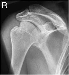
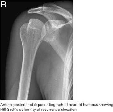
Compression defects, sometimes referred to as hatchet-shaped defects, on the head of the humerus are associated with recurrent dislocation of the shoulder. In the case of recurrent anterior dislocation, the defect will occur on the postero-lateral aspect of the head of the humerus (Hill-Sach's lesion). In the case of recurrent posterior dislocation, the defect will be on the anterior part of the head. In each case, this is where the dislocated head of the humerus impacts on the glenoid rim.
The radiographic examination for recurrent dislocation of the shoulder requires a projection of the glenoid cavity for signs of fracture affecting the inferior rim (Bankart lesion) as well as different projections of the head of the humerus to demonstrate the defect. It is important to remember that the angle formed between the epicondyles of the humerus and the cassette indicates the degree of rotation of the humerus. To judge the rotation of the humerus by the position of the hand can be very misleading. Projections may be selected from the following:
• antero-posterior with the humerus lateral;
• antero-posterior with the humerus oblique;
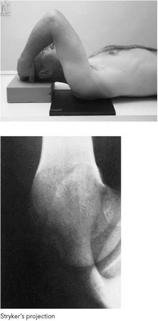
• antero-posterior (modified) - Stryker's;
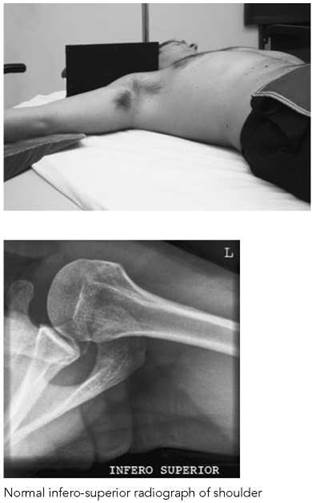
• infero-superior.
Antero-posterior (lateral humerus)
If the patient is able to cooperate fully, these projections may be taken erect. If not, the patient is positioned supine to reduce the risk of movement. An 18 X 24-cm cassette is selected.
Position of patient and cassette
• The patient is positioned erect, with the unaffected shoulder raised approximately 30 degrees to bring the glenoid cavity at right-angles to the centre of the cassette.
• The arm is partially abducted, the elbow flexed and the arm medially rotated. The palm of the hand rests on the patient's waist.
• The cassette is placed with its upper border 5 cm above the shoulder and centred to the joint.
Direction and centring of the X-ray beam
• The horizontal central ray is directed to the head of the humerus and the centre of the cassette.
• Exposure is made on arrested respiration.
Essential image characteristics
• The image should demonstrate the head and neck of the humerus and the glenoid cavity with the glenohumeral joint shown well.
Note
To improve image quality and reduce radiation dose, careful collimation of the beam is employed.
Antero-posterior shoulder (lateral humerus projection) showing Hill-Sachs deformity due to recurrent dislocation
Antero-posterior shoulder showing anterior dislocation
Recurrent dislocation
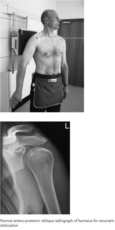
Antero-posterior (oblique humerus)
Position of patient and cassette
• The patient is positioned erect, with the unaffected shoulder raised approximately 30 degrees to bring the glenoid cavity at right-angles to the centre of the cassette.
• The elbow is extended, allowing the arm to rest in partial abduction by the patient's side.
• The humerus is now in an oblique position midway between that for the antero-posterior projection and that for a lateral projection.
• The cassette is placed with its upper border 5 cm above the shoulder and centred to the joint.
Direction and centring of the X-ray beam
• The horizontal central ray is directed to the head of the humerus and the centre of the cassette.
• Exposure is made on arrested respiration.
Essential image characteristics
• The image should demonstrate the head and neck of the humerus and the glenoid cavity, with the glenohumeral joint shown clearly.
Note
To improve image quality and reduce radiation dose, careful collimation of the beam is employed.
Antero-posterior (modified) - Stryker’s
This position will demonstrate a Hills-Sachs deformity of the humeral head.
Position of patient and cassette
• The patient lies supine on the X-ray table.
• The arm of the affected side is extended fully and the elbow then flexed to allow the hand to rest on the patient’s head.
• The line joining the epicondyles of the humerus remains parallel to the tabletop.
• The centre of the cassette is positioned 2.5 cm superior to the head of the humerus.
Direction and centring of the X-ray beam
• The central ray is angled 10 degrees cranially and directed through the centre of the axilla to the head of the humerus and the centre of the cassette.
Infero-superior
This will give a second projection of the glenoid cavity as well as a further projection of the head of the humerus.
Position of patient and cassette
• The patient lies supine on the X-ray table, with the arm of the affected side abducted without causing discomfort to the patient.
• The palm of the hand is turned to face upwards, with the medical and lateral epicondyles of the humerus equidistant from the tabletop.
• A cassette is supported vertically against the shoulder and is pressed against the neck to include as much as possible of the scapula on the film.
• The shoulder and arm are raised slightly on non-opaque pads.
Direction and centring of the X-ray beam
• The horizontal central ray is directed towards the axilla with minimum angulation towards the trunk.
Essential image characteristics
• The image should demonstrate the head of the humerus, the acromion process, the coracoid process and the glenoid cavity of the scapula.
• The lesser tuberosity will be in profile, and the acromion process and the superior aspect of the glenoid will be seen superimposed on the head of the humerus.
Calcified tendons
Most tendon pathology is best demonstrated by MRI or ultrasound. Calcification does not show well on MRI and calcific tendonitis is thus best depicted by plain radiographs or ultrasound. The radiographic technique is described below.
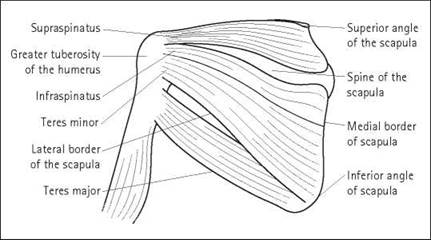
To demonstrate calcifications in the tendons around the shoulder joint by radiography, the course of each tendon, unobstructed by overlaying bone, should be demonstrated, including a profile of each region of the proximal end of the humerus into which a tendon is inserted. The tendons affected are those of the supraspinatus, subscapularis, infraspinatus, and rarely teres minor muscles. The illustration shows the origins, courses and insertions of most of these muscles.
The supraspinatus muscle has its origin in the supraspinatus fossa on the posterior aspect of the scapula superior to the spine of the scapula. Its tendon passes beneath the acromion process then over the upper posterior part of the shoulder joint, to be inserted into the highest of the three impressions of the greater tuberosity.
The infraspinatus muscle has its origin in the infraspinatus fossa on the posterior surface of the scapula inferior to the spine of the scapula. Its tendon glides over the posterior border of the acromion and then passes behind the capsule of the shoulder joint, to be inserted into the middle impression of the greater tuberosity of the humerus.
The teres minor muscle has its origin on the lateral border of the scapula and its tendon passes behind the lower part of the capsule of the shoulder joint, to be inserted into the lowest of the three impressions of the greater tuberosity of the humerus and to the shaft just distal to this lowest impression.
The subscapularis muscle has its origin in the subscapularis fossa on the deep (anterior) surface of the scapula and its tendon crosses the shoulder joint anteriorly, to be inserted into the lesser tuberosity of the humerus.
The recommended projections for each of the tendons are given in the table below (remember ultrasound is very effective in localizing calcification and may also give information about the soft tissue of the tendon).
|
Tendon |
Projection |
Variation |
|
Supraspinatus |
Antero-posterior Lateral outlet view |
No rotation of humerus |
|
Subscapularis |
Infero-superior Antero-posterior |
Lateral rotation of humerus |
|
Infraspinatus |
Antero-posterior Infero-superior |
25° caudad angulation |
|
Teres minor |
Antero-superior |
Medial rotation of humerus |
Calcified tendons
Antero-posterior
An 18 X 24-cm cassette is used in a vertical cassette holder.
Position of patient and cassette
• The patient stands with the affected shoulder against the vertical cassette holder and rotated 15 degrees to bring the plane of the scapula parallel with the cassette.
• The cassette is positioned so that its upper border is at least 5 cm above the shoulder to ensure that the oblique rays do not project the shoulder off the film.
Position of the arm
• The arm is supinated at the patient’s side, palm facing forwards, with the line joining the medial and lateral epicondyles of the humerus parallel to the vertical cassette holder.
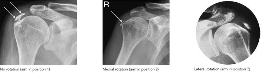
• With the elbow flexed, the arm is partially abducted and medially rotated, with the dorsum of the hand resting on the rear waistline. The line joining the medial and lateral epicondyles of the humerus is now perpendicular to the vertical cassette holder.
• With the elbow flexed, the arm is abducted and laterally rotated, with the hand raised above the shoulder. The palm of the hand faces forward, with the lateral epicondyle facing backwards. The line joining the medial and lateral epicondyles of the humerus should be perpendicular to the vertical cassette holder.
Direction and centring of the X-ray beam
• In each case, the horizontal central ray is directed to the head of the humerus and to the centre of the film.
Essential image characteristics
• In each case, the image should demonstrate the proximal end of the humerus in profile to the tendon under examination.
• Different degrees of rotation will demonstrate whether the calcification moves in relation to the humerus.
• The exposure should be adjusted to show the soft-tissue details - usually 5 kVp less than for general images.


Calcified tendons
Antero-posterior - 25 degrees caudad
Position of patient and cassette
• The patient stands with the affected shoulder against a vertical cassette holder and rotated 15 degrees to bring the plane of the scapula parallel with the cassette.
• The arm is supinated at the patient's side, palm facing forwards, with the line joining the medial and lateral epicondyles of the humerus parallel to the vertical cassette holder.
• To allow for caudal angulation of the X-ray beam, the cassette is adjusted vertically, so that the centre of the cassette is approximately 5 cm distal to the head of the humerus.
Direction and centring of the X-ray beam
• The collimated central ray is angled 25 degrees caudally and centred to the head of the humerus and to the centre of the film.
Demonstrates: insertion of infraspinatus and the subacromial part of the supraspinatus tendon.
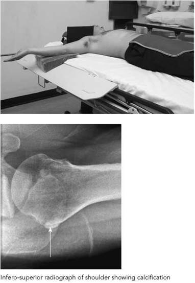
Infero-superior
Position of patient and cassette
• The patient lies supine on the table, with the arm of the side being examined abducted to a right-angle.
• The palm of the hand faces upwards and the line joining the medial and lateral epicondyles is in a plane parallel to the tabletop.
• The cassette is supported vertically against the upper border of the shoulder and pressed into the neck.
Direction and centring of the X-ray beam
• The horizontal central ray is directed to the centre of the axilla, with the minimum angulation towards the trunk.
Demonstrates: the insertion of the subscapularis and teres minor and the course of tendons anterior and posterior to the capsule of the shoulder joint.
Essential image characteristics
• In each case, the image should demonstrate the proximal end of the humerus in profile to the tendon under examination.
Acromioclavicular joints
Antero-posterior
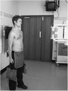
An antero-posterior projection of the joint in question is all that is normally required. In certain circumstances, subluxation of the joint may be confirmed with the patient holding a heavy weight. An 18 X 24-cm cassette is placed in a vertical cassette holder.
Position of patient and cassette
• The patient stands facing the X-ray tube, with the arms relaxed to the side. The posterior aspect of the shoulder being examined is placed in contact with the cassette, and the patient is then rotated approximately 15 degrees towards the side being examined to bring the acromioclavicular joint space at right- angles to the film.
• The cassette is positioned so that the acromion process is in the centre of the film.
Direction and centring of the X-ray beam
• The horizontal central ray is centred to the palpable lateral end of the clavicle at the acromioclavicular joint.
• To avoid superimposition of the joint on the spine of the scapula, the central ray can be angled 25 degrees cranially before centring to the joint.
Essential image characteristics
• The image should demonstrate the acromioclavicular joint and the clavicle projected above the acromion process.
• The exposure should demonstrate soft tissue around the articulation.
Notes
• The normal joint is variable (3-8 mm) in width. The normal difference between the sides should be less than 2-3 mm (Manaster 1997).
• The inferior surfaces of the acromion and clavicle should normally be in a straight line.
Weight-bearing antero-posterior projection
• The acromioclavicular joint has a weak joint capsule and is vulnerable to trauma. Subluxation may be difficult to diagnose in the standard antero-posterior image, because the width of the joint can be variable and may look widened in a normal joint.
• To prove subluxation, it may be necessary to do weight-bearing comparison projections of both acromioclavicular joints (separate joint images).
• The positions of the patient and cassette are as described above.
• It is advisable to 'strap' the weights used for the procedure around the lower arms rather than getting the patient to hold on to them, as the biomechanics involved may lead to a false negative appearance.

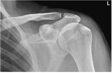
Normal antero-posterior radiograph of acromioclavicular joint
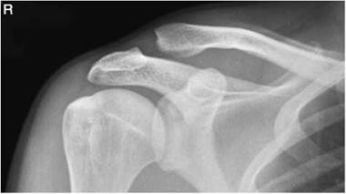
Antero-posterior radiograph of acromioclavicular joint showing subluxation
Clavicle
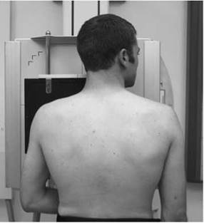
Postero-anterior - erect (basic)
Although the clavicle is demonstrated on the antero-posterior ‘survey’ image, it is desirable to have the clavicle as close to the cassette as possible to give optimum bony detail. The postero- anterior position also reduces the radiation dose to the thyroid and eyes, an important consideration in follow-up fracture images. Alternatively, the patient may be supine on the table or trolley for the antero-posterior projection in which immobility and movement are considerations.
A 24 X 30-cm cassette is placed transversely in an erect cassette holder (or a vertical Bucky if the patient is particularly large).
Position of patient and cassette
• The patient sits or stands facing an erect cassette holder.
• The patient’s position is adjusted so that the middle of the clavicle is in the centre of the cassette.
• The patient’s head is turned away from the side being examined and the affected shoulder rotated slightly forward to allow the affected clavicle to be brought into close contact with the Bucky.
Direction and centring of the X-ray beam
• The horizontal central ray is directed to the centre of the clavicle and the centre of the image, with the beam collimated to the clavicle.
Essential image characteristics
• The entire length of the clavicle should be included on the image.
• The lateral end of the clavicle will be demonstrated clear of the thoracic cage.
• There should be no foreshortening of the clavicle.
• The exposure should demonstrate both the medial and the lateral ends of the clavicle.
Note
Exposure is made on arrested respiration to reduce patient movement.
Normal postero-anterior radiograph of clavicle
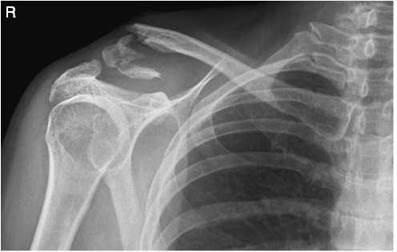
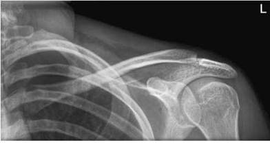
Postero-anterior radiograph of clavicle showing comminuted fracture
Clavicle
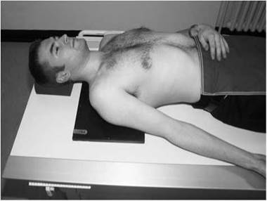
Antero-posterior - supine (alternate)
Position of patient and cassette
• The patient is supine on the X-ray table.
• A small sandbag is placed under the opposite shoulder to rotate the patient slightly towards the affected side to make sure that the medial end of the clavicle is not superimposed on the vertebral column.
• The arm of the side being examined is in a relaxed position by the side of the trunk.
• A 24 X 30-cm cassette is placed transversely behind the patient’s shoulder and adjusted so that the clavicle is in the middle.
Direction and centring of the X-ray beam
• The vertical central ray is directed to the middle of the clavicle.
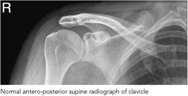
Essential image characteristics
• The entire length of the clavicle should be included on the image.
• The lateral end of the clavicle will be demonstrated clear of the thoracic cage.
• There should be no foreshortening of the clavicle.
• The exposure should demonstrate both the medial and the lateral ends of the clavicle.
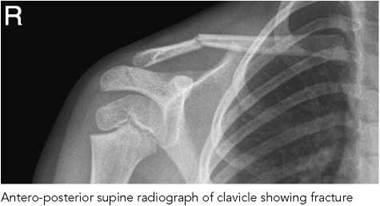
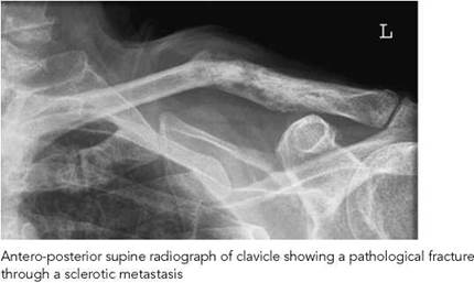
Clavicle
Infero-superior
This projection can be very useful to confirm a possible fracture seen on the postero-anterior/antero-posterior projection, to assess the degree of any fracture displacement and to show the medial end of clavicle clear of underlying ribs.
In cases of acute injury, it is more comfortable for the patient to be examined in the erect position.
Position of patient and cassette
• The patient sits facing the X-ray tube with a 24 X 30-cm cassette placed in the cassette holder. Some holders allow forward-angulation of the cassette of 15 degrees towards the shoulder. This reduces the distortion caused by the cranially projected central beam.
• The unaffected shoulder is raised slightly to bring the scapula in contact with the cassette.
• The patient's head is turned away from the affected side.
• The cassette is displaced above the shoulder to allow the clavicle to be projected into the middle of the image.
Direction and centring of the X-ray beam
• The central ray is angled 30 degrees cranially and centred to the centre of the clavicle.
• The 30 degrees needed to separate the clavicle from the underlying ribs can be achieved by a combination of patient positioning and central ray angulation.
• The medial end of the clavicle can be shown in greater detail by adding a 15-degree lateral angulation to the beam.
Essential image characteristics
• The image should demonstrate the entire length of the clavicle, including the sternoclavicular and acromioclavicular joints.
• The entire length of the clavicle, with the exception of the medial end, should be projected clear of the thoracic cage.
• The clavicle should be horizontal.
Radiological considerations
• If a fracture occurs together with fracture of the upper ribs, then this implies a severe injury and may be associated with subclavian vessel damage or pneumothorax.
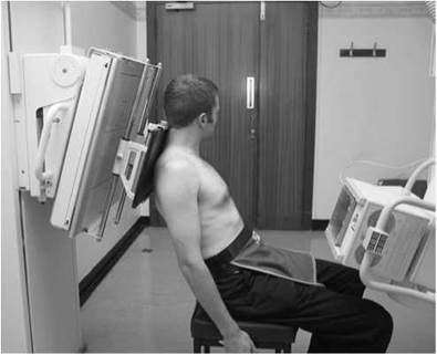
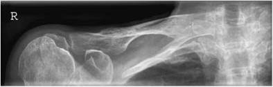
Erect infero-superior radiograph of clavicle

Infero-superior radiograph of clavicle showing fracture
Clavicle
Infero-superior - supine
Position of patient and cassette
• The patient lies supine on the table, with the shoulder of the side being examined raised on a non-opaque pad and with the arm relaxed by the side.
• The patient's head is turned away from the affected side.
• The cassette is tilted back about 20 degrees from the vertical and is supported by sandbags against the upper border of the shoulder and pressed into the side of the neck.
Direction and centring of the X-ray beam
• The central ray is angled 45 degrees cranially and centred to the centre of the clavicle.
Essential image characteristics
• The image should demonstrate the entire length of the clavicle, including the sternoclavicular and acromioclavicular joints.
• The entire length of the clavicle, with the exception of the proximal end, should be projected clear of the thoracic cage.
• The clavicle should be horizontal.
Note
If the cassette cannot be pressed well into the side of the neck, then the medial end of the clavicle might not be included on the cassette. In this case, with the central ray again angled 45 degrees cranially, the central ray is first centred to the sternoclavicular joint of the affected side and then the tube is rotated until the central ray is directed to the centre of the clavicle.
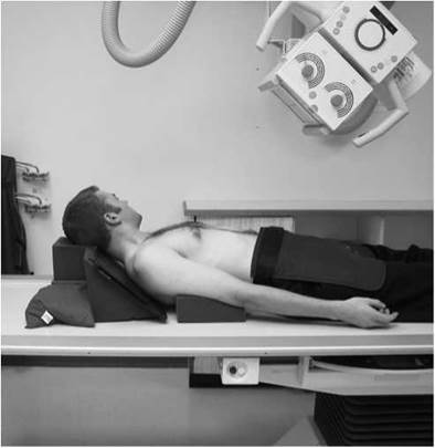
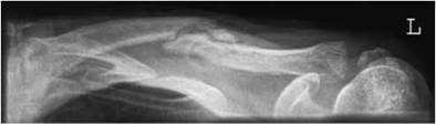
Supine infero-superior radiograph of clavicle showing early healing of a fracture
Sternoclavicular joints
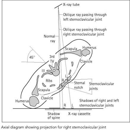
In an antero-posterior or postero-anterior projection, the vertebral column will be superimposed on, and obscure, the sternoclavicular joints, hence an oblique projection is required to show the joint space clear of the vertebral column. An oblique projection is chosen that will bring the joint space as near as possible at right-angles to the film. Both sides may be imaged for comparison.
Postero-anterior oblique (basic)
Position of patient and cassette
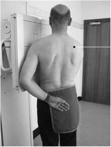
• The patient stands facing the Bucky.
• The patient is then rotated through 45 degrees so that the median sagittal plane of the body is at 45 degrees to the cassette with the sternoclavicular joint being examined nearer the cassette and centred to it.
• The patient holds the vertical stand to help immobilization and continues to breathe during the exposure.
Direction and centring of the X-ray beam
• The horizontal central ray is centred at the level of the fourth thoracic vertebra to a point 10 cm away from the midline on the side away from the cassette.
Essential image characteristics
• The sternoclavicular joint should be demonstrated clearly in profile away from the vertebral column.
Note
Superimposed lung detail may be reduced by asking the patient to breathe gently during the exposure.
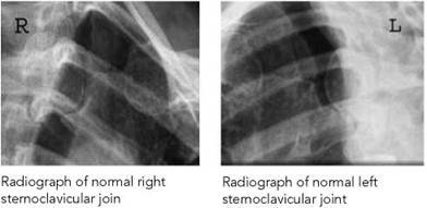
Semi-prone (alternate)
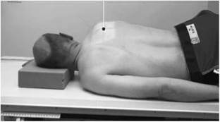
Alternatively, the patient may be examined in the semi-prone position. Starting with the patient prone, the side not being examined is raised from the table until the median sagittal plane is at 45 degrees to the table, with the joint being examined in the midline of the table. The centring point is to the raised side, 10 cm from the midline at the level of the fourth thoracic vertebra.
Radiological considerations
• These joints are difficult to demonstrate, even with good technique. Alternatives include ultrasound, CT (especially with three-dimensional or multiplanar reconstructions) and MRI.
Sternoclavicular joints
Postero-anterior
Using a single-exposure technique, both joints are imaged for comparison in a case of suspected subluxation.
A 24 X 30-cm cassette is used, placed transversely in an erect cassette holder.
Position of patient and cassette
• The patient sits or stands facing an erect cassette holder with their chin resting on the top of the cassette holder.
• The patient’s position is adjusted so that the median sagittal plane is at right angles to the vertical central line of the cassette.
• The cassette is adjusted vertically to the level of the middle of the manubrium.
• The arms are extended by the sides of the body or alternatively the patient can hold onto the cassette holder.
Direction and centring of the X-ray beam
• The horizontal central ray is centred in the midline of the thorax at the level of the head of the humerus.
Notes
• The radiographic exposure is similar to that given for an antero-posterior shoulder projection on the patient.
• The beam is collimated to the sternoclavicular joints.
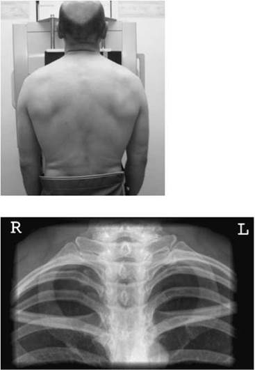
Radiograph of normal sternoclavicular joints in postero-anterior projection
Lateral
An 18 X 24-cm cassette is used, placed vertically in an erect cassette holder.
Position of patient and cassette
• The patient sits or stands sideways with the affected side adjacent to the cassette.
• The median sagittal plane is adjusted parallel to the cassette with the upper arm in contact with it.
• the patient clasps the hands behind and pulls the shoulders well back to avoid any obscuring of the joints.
• The centre of the cassette is adjusted to coincide with the level of the sternoclavicular joints.
Direction and centring of the X-ray beam
• The horizontal central ray is centred to the palpable sternoclavicular joints just below the sternal notch.
Note
• Ideally anterior subluxation is diagnosed clinically. Posterior subluxation compromises the airway.
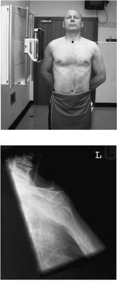
Radiograph of normal sternoclavicular joints in lateral projection
Scapula
The position of the scapula relative to the thorax changes as the arm moves through abduction, adduction, flexion, extension and rotation. When the shoulders are pressed back, the medial borders for the scapulae are parallel to and near the vertebral column, so that most of the scapula would be superimposed on the thoracic cage in the antero-posterior projection of the scapula. With the arm in full medial rotation, the scapula glides laterally over the ribs, allowing more of the body of the scapula to be shown clearly against the rib cage.
A 24 X 30-cm cassette is used, placed vertically in an erect cassette holder or a Bucky if the patient is large.
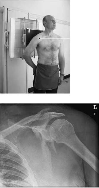
Antero-posterior radiograph of scapula showing a fracture through the neck of the glenoid
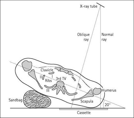
Axial diagram showing the relationship of cassette and X-ray beam to the scapula
Antero-posterior (basic) - erect
The scapula can be shown on the antero-posterior basic survey projection of the shoulder but with the arm in medial rotation. It is preferable for the patient to be examined in the erect position when there is suspected injury as it is more comfortable. There may also be underlying rib fractures.
Position of patient and cassette
• The patient stands with the affected shoulder against a cassette and rotated slightly to bring the plane of the scapula parallel with the cassette.
• The arm is slightly abducted away from the body and medially rotated.
• The cassette is positioned so that its upper border is at least 5 cm above the shoulder to ensure that the oblique rays do not project the shoulder off the cassette.
Direction and centring of the X-ray beam
• The horizontal ray is directed to the head of the humerus.
Note
A long exposure time may be chosen and the patient allowed to continue quiet breathing during the exposure, so that images of overlying lung and rib are blurred in cases of non-trauma.
Essential image characteristics
• The entire scapula should be demonstrated on the image.
• The medial border of the scapula should be projected clear of the mediastinum.
• The medial border of the scapula should be projected clear of the ribs.
Scapula
Lateral (basic)
Position of patient and cassette
• The patient stands with the side being examined against a vertical Bucky.
• The patient's position is adjusted so that the centre of the scapula is at the level of the centre of the cassette.
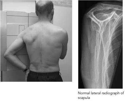
• The arm is either adducted across the body or abducted with the elbow flexed to allow the back of the hand to rest on the hip.
• Keeping the affected shoulder in contact with the Bucky, the patient's trunk is rotated forward until the body of the scapula is at right-angles to the cassette. This can be checked by palpating the medial and lateral borders of the scapula near the inferior angle.
Direction and centring of the X-ray beam
• The horizontal central ray is directed to the midpoint of the medial border of the scapula and to the middle of the cassette.
Essential image characteristics
• The scapula should be demonstrated clear of the ribs.
• The medial and lateral borders should be superimposed.
• The humerus should be projected clear of the area under examination.
• The exposure should demonstrate adequately the whole of the scapula.
Lateral (alternate)
Position of patient and cassette
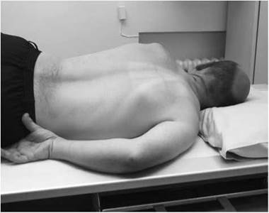
• The patient lies prone on the X-ray table.
• The arm on the side being examined is slightly abducted and the elbow flexed.
• The unaffected side is raised until the palpable body of the scapula is at right-angles to the table and in the midline of the table.
Direction and centring of the X-ray beam
• The vertical central ray is directed just medial to the midpoint of the palpable medial border of the scapula and to the middle of the Bucky table.
Radiological considerations
• This is a very thin sheet of bone with several dense appendages overlying the upper ribs, making fractures, and their full extent, hard to assess. CT may be very useful for complete evaluation, in particular the multiplanar reconstruction facility, once a fracture has been detected.

Coracoid process
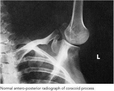
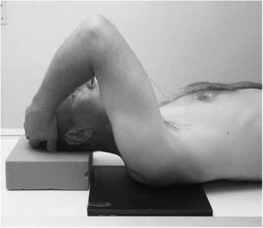
The coracoid process is demonstrated more clearly in an anteroposterior projection, with the arm abducted to above-shoulder level. Additionally, the process is demonstrated in the axial (supero-inferior and infero-inferior) projections of the shoulder (see pp. 81 and 82).
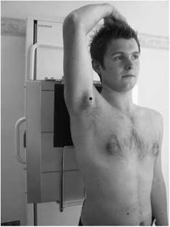
Antero-posterior (arm abducted)
A 24 X 30-cm cassette is placed in an erect cassette holder or a vertical Bucky if the patient is large.
Position of patient and cassette
• The patient is supine or erect, with the posterior aspect of the affected shoulder against the cassette.
• The arm of the affected side is abducted to above-shoulder level and the elbow flexed, allowing the hand to rest on the patient's head.
• The patient is now rotated slightly to bring the affected side away from the cassette.
• The position of the cassette is adjusted so that it is centred to the axilla.
Direction and centring of the X-ray beam
• The central ray is directed at right-angles to the cassette and centred to the axilla of the affected side.
Note
This projection will also demonstrate the acromioclavicular joint of the same side free from overlaying structures.