
Recommended projections

Positioning terminology
Rotation of the lower limb occurs at the hip joint. The position of the foot relates to the direction of rotation.
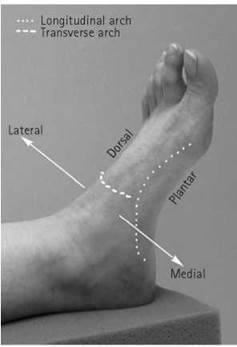
• Dorsal surface: the superior surface of the foot is known as the dorsal surface and slopes downwards, at a variable angle, from the ankle to the toes and from medial to lateral.
• Plantar aspect: the inferior surface of the foot is known as the plantar aspect.
• Medial aspect: the surface nearer the midline of the body is the medial aspect.
• Lateral aspect: the surface further from the midline of the body is the lateral aspect.
• Medial rotation: the lower limb is rotated inwards, so that the anterior surface faces medially. This will produce internal rotation of the hip joint.
• Lateral rotation: the lower limb is rotated outwards, so that the anterior surface faces laterally. This will produce external rotation of the hip joint.
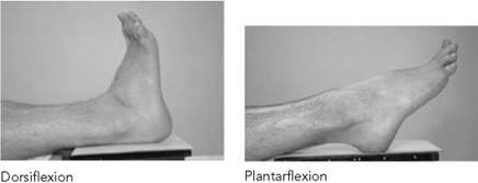
• Dorsiflexion: dorsiflexion of the ankle joint occurs when the dorsal surface of the foot is moved in a superior direction.
• Plantarflexion: plantarflexion of the ankle joint occurs when the plantar surface of the foot is moved in an inferior direction.
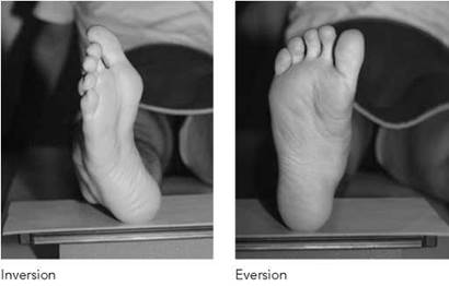
• Inversion: inversion of the foot occurs when the plantar surface of the foot is turned to face medially, with the limb extended.
• Eversion: eversion of the foot occurs when the plantar surface of the foot is turned to face laterally, with the limb extended.
• Flexion of the knee joint: the degree of flexion of the knee joint relates to the angle between the axis of the tibia when the knee is extended and the angle of the axis of the tibia when the knee is flexed.

Foot
Basic projections
It is common practice to obtain two projections, a dorsi-plantar and a dorsi-plantar oblique, using a 24 X 30-cm high-resolution cassette. A lead-rubber mask is used to mask off each half of the cassette not in use.
Dorsi-plantar (basic)
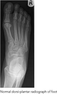
To ensure the tarsal and tarso-metatarsal joints are demonstrated, the foot is X-rayed with the foot flat on the cassette and with the X-ray tube angled 15 degrees cranially. Alternatively, the foot is raised on a 15-degree non-opaque pad using a vertical central beam. The angulation compensates for the inclination of the longitudinal arch and reduces overshadowing of the tarsal bones.
Position of patient and cassette
• The patient is seated on the X-ray table, supported if necessary, with the affected hip and knee flexed.
• The plantar aspect of the affected foot is placed on the cassette and the lower leg is supported in the vertical position by the other knee.
• Alternatively, the cassette can be raised on a 15-degrees foam pad for ease of positioning.
Direction and centring of the X-ray beam
• The central ray is directed over the cuboid-navicular joint, midway between the palpable navicular tuberosity and the tuberosity of the fifth metatarsal.
• The X-ray tube is angled 15 degrees cranially when the cassette is flat on the table.
• The X-ray tube is vertical when the cassette is raised on a 15-degree pad.

Essential image characteristics
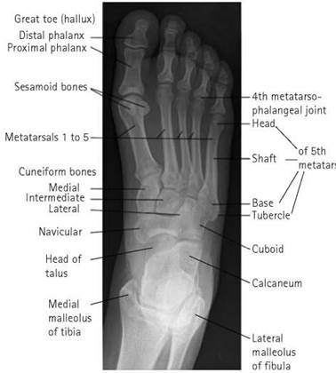
• The tarsal and tarso-metatarsal joints should be demonstrated when the whole foot is examined.
• The kVp selected should reduce the difference in subject contrast between the thickness of the toes and the tarsus to give a uniform radiographic contrast over the range of foot densities.
Note
A wedge filter can be used to compensate for the difference in tissue thickness.
Foot 4
Dorsi-plantar oblique
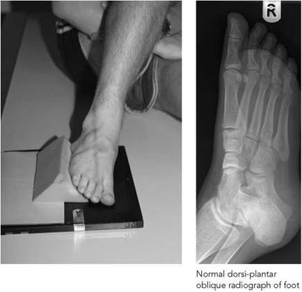
This projection allows the alignment of the metatarsals with the distal row of the tarsus to be assessed.
Position of patient and cassette
• From the basic dorsi-plantar position, the affected limb is allowed to lean medially to bring the plantar surface of the foot approximately 30-45 degrees to the cassette.
• A non-opaque angled pad is placed under the foot to maintain the position, with the opposite limb acting as a support.
Direction and centring of the X-ray beam
• The vertical central ray is directed over the cuboid-navicular joint.
Essential image characteristics
• The kVp selected should reduce the difference in subject contrast between the thickness of the toes and the tarsus to give a uniform radiographic contrast over the range of foot densities.
• A wedge filter may also be used to give a uniform range of densities.
• The dorsi-plantar oblique should demonstrate the inter-tarsal and tarso-metatarsal joints.
Note
For non-ambulant/wheelchair-bound patients, the cassette may be placed on a pad or stool directly in contact with the plantar aspect of the foot.
Radiological considerations
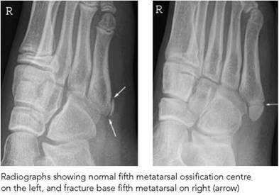
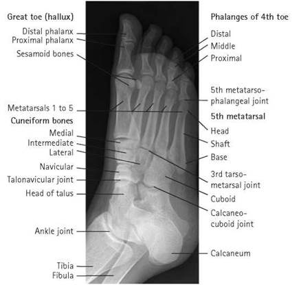
• There are numerous possible accessory ossicles in the foot and around the ankle, as at the wrist. These may give rise to confusion with small avulsion injuries.
• The base of the fifth metatarsal ossifies from the accessory ossification centre, which is oriented parallel to the long axis of the bone. This should not be confused with a fracture, which usually runs transversely.
• If the accessory ossification centre is not parallel to the metatarsal, then this may be due to an avulsion injury.
• Lisfranc fracture dislocations at the bases of the metatarsals are difficult to see, except on oblique projections, and will be masked by underexposure.
Foot
Lateral
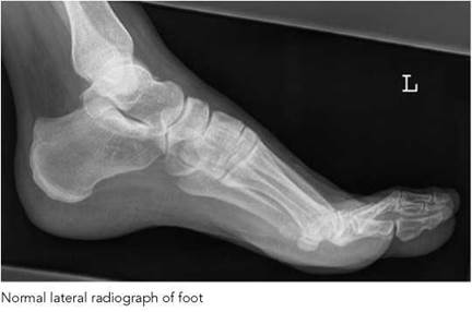
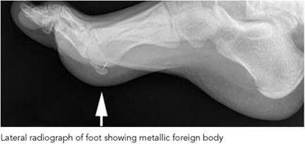
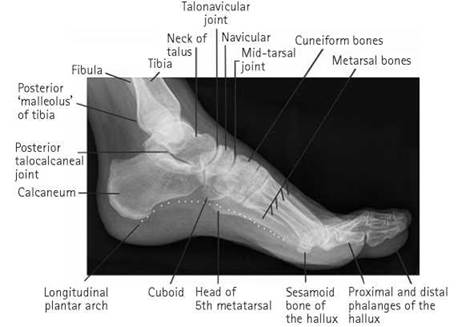
This is used in addition to the routine dorsi-planter projection to locate a foreign body. It may also be used to demonstrate a fracture or dislocation of the tarsal bones, or base of metatarsal fractures or dislocation.
Position of patient and cassette
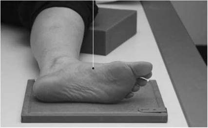
• From the dorsi-plantar position, the leg is rotated outwards to bring the lateral aspect of the foot in contact with the cassette.
• A pad is placed under the knee for support.
• The position of the foot is adjusted slightly to bring the plantar aspect perpendicular to the cassette.
Direction and centring of the X-ray beam
• The vertical central ray is centred over the navicular cuneiform joint.
Essential image characteristics
• If examining for a suspected foreign body, the kVp selected should be adequate to show the foreign body against the soft- tissue structures.
Note
A metal marker placed over the puncture site is commonly used to aid localization of the foreign body.
Foot
Lateral - erect
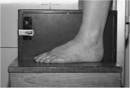
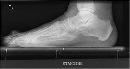
Normal erect lateral projection of foot
This projection is used to demonstrate the condition of the longitudinal arches of the foot, usually in pes planus (flat feet). Both feet are examined for comparison.
Position of patient and cassette
• The patient stands on a low platform with a cassette placed vertically between the feet.
• The feet are brought close together The weight of the patient’s body is distributed equally.
• To help maintain the position, the patient should rest their forearms on a convenient vertical support, e.g. the vertical Bucky.
Direction and centring of the X-ray beam
• The horizontal central ray is directed towards the tubercle of the fifth metatarsal.
Dorsi-plantar - erect
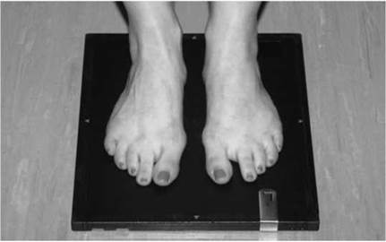
This projection can be used to show the alignment of the metatarsals and phalanges in cases of hallux valgus. Both forefeet are taken for comparison.
Position of patient and cassette
• The patient stands with both feet on the cassette.
• The cassette is positioned to include all the metatarsals and phalanges.
• The weight of the patient’s body is distributed equally.
• To help maintain the position, the patient should rest the forearms on a convenient vertical support, e.g. the vertical Bucky.
Direction and centring of the X-ray beam
• The vertical ray is centred midway between the feet at the level of the first metatarso-phalangeal joint.
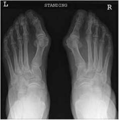
Dorsi-plantar erect projection of both feet showing hallux valgus
Toes
Basic projections
It is common practice to obtain two projections, a dorsi-plantar and a dorsi-plantar oblique, using a 18 X 24-cm high-resolution cassette. A lateral projection is taken for fractures of the hallux phalanx. A lead-rubber mask can be used to mask off each half of the cassette not in use.
Dorsi-plantar - basic
Position of patient and cassette
• The patient is seated on the X-ray table, supported if necessary, with hips and knees flexed.
• The plantar aspect of the affected foot is placed on the cassette. This cassette may be supported on a 15-degree pad.
• The leg may be supported in the vertical position by the other knee.
Direction and centring of the X-ray beam
• The vertical central ray is directed over the third metatarsophalangeal joint, perpendicular to the cassette if all the toes are to be imaged.
• For single toes, the vertical ray is centred over the metatarsophalangeal joint of the individual toe and collimated to include the toe either side.
Dorsi-plantar oblique - basic
Position of patient and cassette
• From the basic dorsi-plantar position, the affected limb is allowed to lean medially to bring the plantar surface of the foot approximately 45 degrees to the cassette.
• A 45-degree non-opaque pad is placed under the side of the foot for support, with the opposite leg acting as a support.
Direction and centring of the X-ray beam
• The vertical ray is centred over the first metatarso-phalangeal joint if all the toes are to be imaged and angled sufficiently to allow the central ray to pass through the third metatarsophalangeal joint.
• For single toes, the vertical ray is centred over the metatarsophalangeal joint of the individual toe, perpendicular to the cassette.
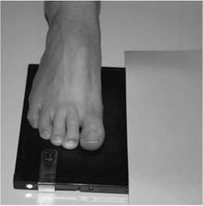
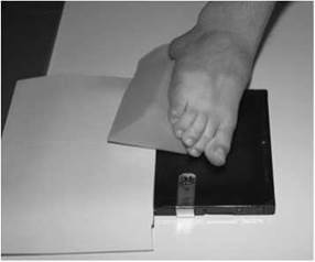
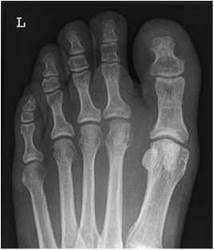
Normal dorsi-plantar projection of all toes
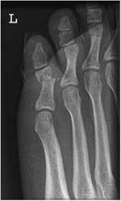
Collimated dorsi-plantar oblique projection of fifth toe, showing fracture of the proximal phalanx
Position of patient and cassette
• From the dorsi-plantar position, the foot is rotated medially until the medial aspect of the hallux is in contact with the cassette. A bandage is placed around the remaining toes (provided that no injury is suspected) and they are gently pulled forwards by the patient to clear the hallux. Alternatively, they may be pulled backwards; this shows the metatarsophalangeal joint more clearly.

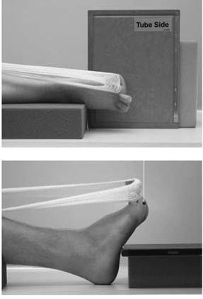

Lateral (basic) - hallux
Direction and centring of the X-ray beam
• The vertical ray is centred over the first metatarso-phalangeal joint.
First metatarsal-phalangeal sesamoid bones
The sesamoid bones are demonstrated on the lateral foot projection. However, when requested specifically, a modified lateral and an axial projection may be necessary for further demonstration.
Lateral
Position of patient and cassette
• The patient lies on the unaffected side, and the medial aspect of the affected leg and foot is placed in contact with the table.
• The cassette is placed under the foot to include the phalanges of the hallux and the distal part of the first metatarsal.
• The hallux is then dorsiflexed with the aid of a bandage and held by the patient.
Direction and centring of the X-ray beam
• Centre with the vertical ray perpendicular to the cassette, over the first metatarso-phalangeal joint.
Axial
Position of patient and cassette
There is a choice of two positions for this projection:
1 The patient is positioned as for the lateral projection of the foot. The foot is raised on a support and the cassette is supported vertically and well into the instep. A horizontal beam is used in this case.
2 The patient sits on the X-ray table, with legs extended. The hallux is then dorsiflexed with the aid of a bandage and held by the patient. The cassette is raised on a support and positioned firmly against the instep.
Direction and centring of the X-ray beam
• Centre to the sesamoid bones with the central ray projected tangentially to the first metatarso-phalangeal joint.
Ankle joint
Basic projections
Two projections are routinely taken, an antero-posterior and a lateral, using an 18 X 24-cm high-resolution cassette. A lead-rubber mask can be used to mask off the half of the film not in use.
Antero-posterior - basic (Mortice projection)
Position of patient and cassette
• The patient is either supine or seated on the X-ray table with both legs extended.
• A pad may be placed under the knee for comfort.
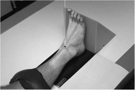
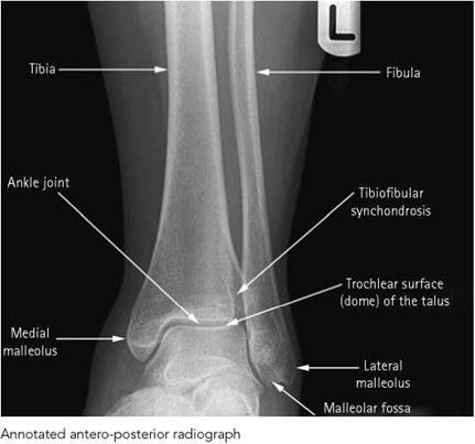
• The affected ankle is supported in dorsiflexion by a firm 90-degree pad placed against the plantar aspect of the foot. The limb is rotated medially (approximately 20 degrees) until the medial and lateral malleoli are equidistant from the cassette.
• The lower edge of the cassette is positioned just below the plantar aspect of the heel.
Direction and centring of the X-ray beam
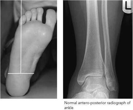
• Centre midway between the malleoli with the vertical central ray at 90 degrees to an imaginary line joining the malleoli.
Essential image characteristics
• The lower third of the tibia and fibula should be included.
• A clear joint space between the tibia, fibula and talus should be demonstrated (commonly called the Mortice view).
Common faults and remedies
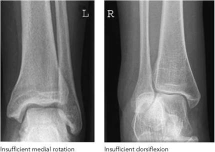
• Insufficient dorsiflexion results in the calcaneum being superimposed on the lateral malleolus.
• Insufficient medial rotation causes overshadowing of the tibiofibular joint with the result that the joint space between the fibula and talus is not demonstrated clearly.
• If internal rotation of the limb is difficult, then the central ray is angled to compensate, making sure that it is still at 90 degrees to the imaginary line joining the malleoli.
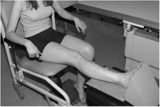
Position of patient and cassette
• With the ankle dorsiflexed, the patient turns on to the affected side until the malleoli are superimposed vertically and the tibia is parallel to the cassette.

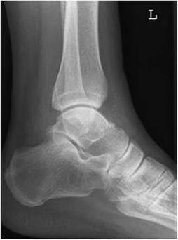
Normal lateral radiograph of ankle
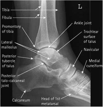
Annotated radiograph of lateral ankle
Lateral (basic) - medio-lateral
• A 15-degree pad is placed under the lateral border of the forefoot and a pad is placed under the knee for support. The lower edge of the cassette is positioned just below the plantar aspect of the heel.
Direction and centring of the X-ray beam
• Centre over the medial malleolus, with the central ray at right-angles to the axis of the tibia.
Essential image characteristics
• The lower third of the tibia and fibula should be included.
• The medial and lateral borders of the trochlear articular surface of the talus should be superimposed on the image.
Common faults and remedies
• Over-rotation causes the fibula to be projected posterior to the tibia and the medial and lateral borders of the trochlear articulations are not superimposed.
• Under-rotation causes the shaft of the fibula to be superimposed on the tibia and the medial and lateral borders of the trochlear articulations are not superimposed.
• The base of the fifth metatarsal and the navicular bone should be included on the image to exclude fracture.
Radiological considerations
• Inversion injury of the ankle is common and may result in fracture of the lateral malleolus or the base of the fifth metatarsal. Investigation of the injury should therefore cover both areas.
• Tear of the collateral ligaments without bone fracture may make the ankle unstable, despite a normal radiograph. Stress projections may clarify this problem and ultrasound or MRI may be useful. Complex injuries may occur with fracture of both malleoli, rendering the ankle mortise very unstable, especially if associated with fracture of the posterior tibia - the so- called trimalleolar fracture - and/or disruption of the distal tibio-fibular synchondrosis. These injuries frequently require surgical fixation.

Ankle joint
Alternative projection methods
In cases of trauma, the techniques may be modified to obtain the basic radiographs without moving the patient from a wheelchair or turning the leg of a patient lying on a trolley. This also applies to those patients from the fracture clinic with below-knee plaster casts. In the latter case, for conventional film processing, radiography cassettes with standard-speed screens are used because of the increase in radiation dose necessary to penetrate the cast.
The horizontal techniques described can be undertaken only in X-ray rooms that have the capability of lowering the ceiling tube suspension sufficiently to centre the X-ray beam on the ankle joint.
Antero-posterior
Position of patient and cassette
• From the sitting position, whilst the patient is in a wheelchair, the whole limb is raised and supported on a stool and a pad is placed under the raised knee for support.
• The lower limb is rotated medially, approximately 20 degrees, until the medial and lateral malleoli are equidistant from the cassette. A non-opaque angled pad is placed against the medial border of the foot and sandbags are placed at each side of the leg for support.
• The lower edge of the cassette is placed just below the plantar aspect of the heel.
Direction and centring of the X-ray beam
• Centre midway between the malleoli, with the vertical central ray at 90 degrees to the imaginary line joining the malleoli or compensatory angulation of the beam if the foot is straight.
Note
If the foot remains straight, there will be overshadowing of the tibio-fibular joint combined with a vertical central ray.
Lateral (alternate) - latero-medial (horizontal beam)
Position of patient and cassette
• With the patient maintaining the sitting position or lying on the trauma trolley, the limb is raised and supported on a firm non-opaque pad.
• A cassette is placed against the medial aspect of the limb. The lower edge of the cassette is placed just below the plantar aspect of the heel.
Direction and centring of the X-ray beam
• The horizontal central ray is directed to the lateral malleolus.
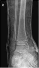
Antero-posterior radiograph through plaster showing fracture of the distal fibula


Horizontal beam lateral radiograph of ankle through plaster
Note
If there is no internal rotation of the foot, then the distal fibula will be projected behind the distal tibia and a ‘true lateral’ image is not produced. If the foot cannot be rotated to superimpose the malleoli, then compensatory superior angulation (approximately 20 degrees) can be applied to the beam.
Stress projections of the ankle joint are taken to demonstrate subluxation due to rupture of the lateral ligaments. Although these projections may be done in the department, they are now commonly done in theatre using a mobile image intensifier.
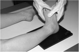
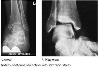
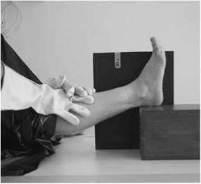
Lateral projection with stress showing subluxation
Stress projections for subluxation
Stress is applied to the joint by medical personnel, usually an orthopaedic surgeon.
Antero-posterior - stress
Position of patient and cassette
• The patient and cassette are positioned for the routine antero-posterior projection.
• The doctor in charge forcibly inverts the foot without internally rotating the leg.
Direction and centring of the X-ray beam
• Centre midway between the malleolus, with the central ray at right-angles to the imaginary line joining the malleoli.
Lateral - stress
Position of patient and cassette
• The patient lies supine on the table, with the limb extended.
• The foot is elevated and supported on a firm pad.
• The ankle is dorsiflexed and the limb rotated medially until the malleoli are equidistant from the tabletop.
• The film is supported vertically against the medial aspect of the foot.
• The doctor applies firm downward pressure on the lower leg.
Direction and centring of the X-ray beam
• Centre to the lateral malleoli with a horizontal beam.
Notes
• The antero-posterior stress projection demonstrates widening of the joint space if the calcaneo-fibular joint space is torn.
• The lateral stress views demonstrate anterior subluxation if the anterior talo-fibular ligament is torn.
• Similar techniques are used in theatre, with the image intensifier positioned above the ankle. The degree of stress applied is viewed and recorded.
Radiation protection
• The doctor applying the stress must wear a suitable lead protective apron and gloves.
• If the technique is done using a mobile image intensifier, then local rules must be implemented and all staff must be provided with protective clothing.
Calcanéum
Basic projections
It is common practice to take two projections, a lateral and an axial, using an 18 X 24-cm cassette fitted with high-resolution intensifying screens. A lead-rubber mask may be used to mask off each half of the film not in use.
Lateral - basic
Position of patient and cassette
• From the supine position, the patient rotates on to the affected side.
• The leg is rotated until the medial and lateral malleoli are superimposed vertically.
• A 15-degree pad is placed under the anterior aspect of the knee and the lateral border of the forefoot for support.
• The cassette is placed with the lower edge just below the plantar aspect of the heel.
Direction and centring of the X-ray beam
• Centre 2.5 cm distal to the medial malleolus, with the vertical central ray perpendicular to the cassette.
Essential image characteristics
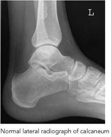
• The adjacent tarsal bones should be included in the lateral projection, together with the ankle joint.
Note
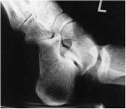
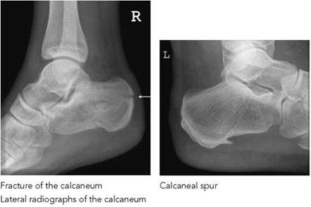
This projection is used to demonstrate calcaneal spurs. For comparison, a radiograph of both heels in the lateral position may be necessary.
Radiological considerations
• The normal juvenile calcaneal apophysis is dense and often appears fragmented. The appearance rarely obscures a fracture and should rarely, if ever, require projections of the contralateral side for assessment.
• The primary trabeculae of bones follow lines of maximum load. In the calcaneum, this results in an apparent lucency in the central area. This should not be mistaken for pathology.
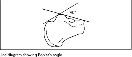
• Fracture of the calcaneum due to heavy landing on the heel causes a compression injury with depression of the central area by the talus. This is seen as flattening of the Bohler’s angle to less than 40 degrees, as shown in the diagram.
• Small spurs or ‘tug’ lesions at attachments of the Achilles tendon and plantar ligament are common. If significant, they are usually ill-defined and clinically tender. Ultrasound may help in their assessment. Computed tomography (CT) is very useful for the complete evaluation of complex calcaneal fractures, especially utilizing the direct coronal plane, multipla- nar and three-dimensional reconstructions.

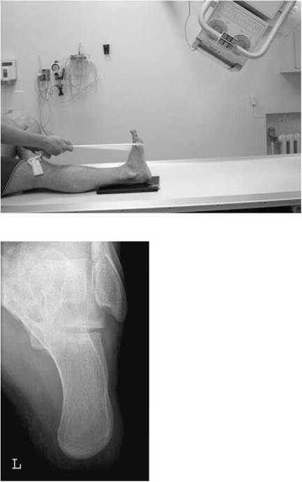
Normal axial projection of calcaneum
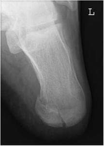
Axial projection of calcaneum showing fracture
Axial - basic
Position of patient and cassette
• The patient sits or lies supine on the X-ray, table with both limbs extended.
• The affected leg is rotated medially until both malleoli are equidistant from the film.
• The ankle is dorsiflexed The position is maintained by using a bandage strapped around the forefoot and held in position by the patient.
• The cassette is positioned with its lower edge just distal to the plantar aspect of the heel.
Direction and centring of the X-ray beam
• Centre to the plantar aspect of the heel at the level of the tubercle of the fifth metatarsal.
• The central ray is directed cranially at an angle of 40 degrees to the plantar aspect of the heel.
Essential image characteristics
• The subtalar joint should be visible on the axial projection.
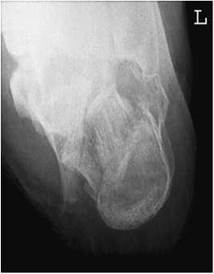
Axial projection of calcaneum showing comminuted fracture
Recommended projections
There are three articular surfaces of the subtalar joint: anterior, middle and posterior. The projections undertaken with the articulations demonstrated are shown in the table below, with matching images also given.
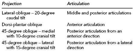
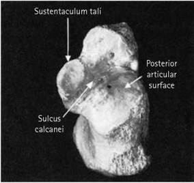
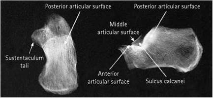

Dorsi-plantar oblique
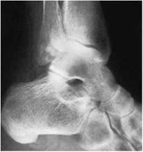
Lateral oblique 20-degree caudal tilt
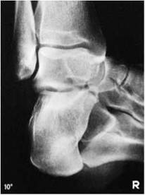
45-degree oblique lateral with 10-degree cranial tilt

45-degree oblique lateral with 15-degree cranial tilt
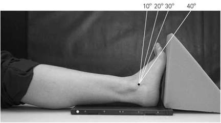
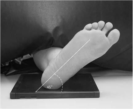
Oblique medial
Position of patient and cassette
• The patient lies supine on the X-ray table, with the affected limb extended.
• The ankle joint is dorsiflexed and the malleoli are equidistant from the film.
• The leg is internally rotated through 45 degrees.
• A pad is placed under the knee for support.
• A non-opaque square pad and sandbag may be placed against the plantar aspect of the foot to keep the ankle joint in dorsiflexion.
• The lower edge of the cassette is placed at the level of the plantar aspect of the heel.
Direction and centring of the X-ray beam
• Centre 2.5 cm distal to the lateral malleolus with the following cranial angulations:

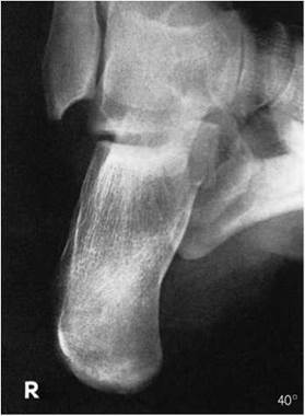
Radiograph showing effect of 40-degree angulation
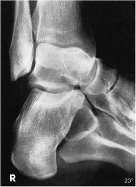
Radiograph showing effect of 20-degree angulation
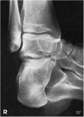
Radiograph showing effect of 10-degree angulation
Oblique lateral
Position of patient and cassette
• The patient lies supine on the X-ray table, with the affected limb extended.
• The ankle joint is dorsiflexed and the malleoli are equidistant from the cassette.
• The leg is externally rotated through 45 degrees.
• A pad is placed under the knee for support.
• A non-opaque square pad and sandbag may be placed against the plantar aspect of the foot to keep the ankle joint in dorsiflexion.
• The lower edge of the cassette is placed at the level of the plantar aspect of the heel.
Direction and centring of the X-ray beam
• Centre 2.5 cm distal to the medial malleolus, with the central ray angled 15 degrees cranially.
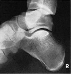
Oblique lateral with 15 degrees cranial tube angulation
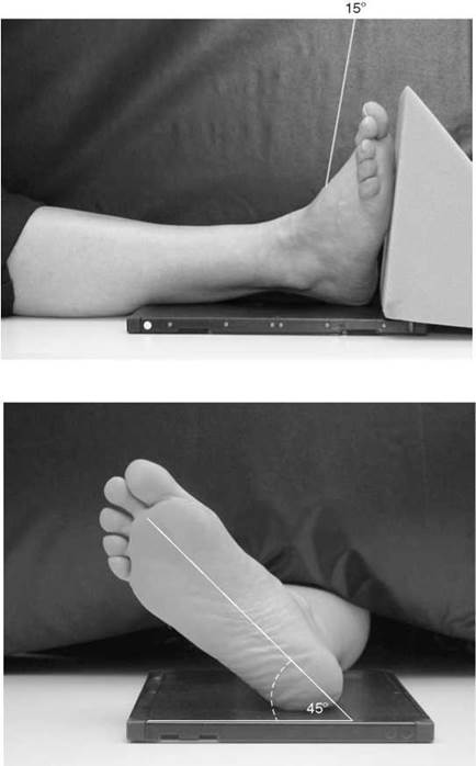
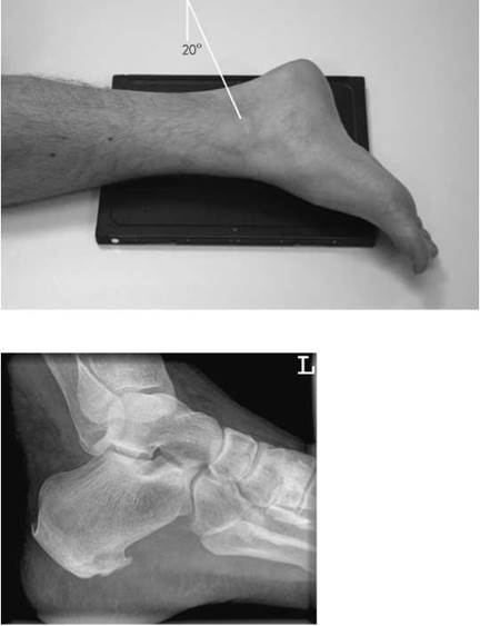
Radiograph of subtalar joints - lateral oblique projection
Lateral oblique
Position of patient and cassette
• The patient lies on the affected side.
• The opposite limb is flexed and brought in front of the affected limb.
• The affected foot and leg are now further rotated laterally until the plantar aspect of the foot is approximately 45 degrees to the cassette.
• The lower edge of the cassette is positioned just below the plantar aspect of the heel.
Direction and centring of the X-ray beam
• Centre to the medial malleolus, with the central ray angled 20 degrees caudally.
Tibia and fibula
Basic projections
Two projections are taken of the full length of the lower leg. A cassette fitted with standard intensifying screens is chosen that is large enough to accommodate the entire length of the tibia and fibula.
Antero-posterior - basic
Position of patient and cassette
• The patient is either supine or seated on the X-ray table, with both legs extended.
• The ankle is supported in dorsiflexion by a firm 90-degree pad placed against the plantar aspect of the foot. The limb is rotated medially until the medial and lateral malleoli are equidistant from the cassette.
• The lower edge of the cassette is positioned just below the plantar aspect of the heel.
Direction and centring of the X-ray beam
• Centre to the middle of the cassette, with the central ray at right-angles to both the long axis of the tibia and an imaginary line joining the malleoli.
Lateral - basic
Position of patient and cassette
• From the supine/seated position, the patient rotates on to the affected side.
• The leg is rotated further until the malleoli are superimposed vertically.
• The tibia should be parallel to the cassette.
• A pad is placed under the knee for support.
• The lower edge of the cassette is positioned just below the plantar aspect of the heel.
Direction and centring of the X-ray beam
• Centre to the middle of the cassette, with the central ray at right-angles to the long axis of the tibia and parallel to an imaginary line joining the malleoli.
Essential image characteristics
• The knee and ankle joints must be included, since the proximal end of the fibula may also be fractured when there is a fracture of the distal fibula.
Notes
• If it is impossible to include both joints on one image, then two films should be exposed separately, one to include the ankle and the other to include the knee. Both images should include the middle third of the lower leg, so the general alignment of the bones may be seen.


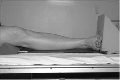
• If it is impossible for the patient to rotate on to the affected side, then the cassette should be supported vertically against the medial side of the leg and the beam directed horizontally to the middle of the cassette.
Proximal tibio-fibular joint
Basic projections
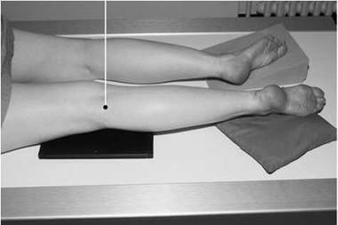

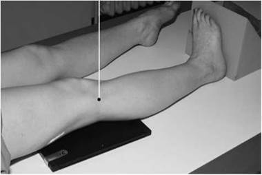

Either a lateral oblique or an anterior oblique projection is taken to demonstrate the tibio-fibular articulation.
Lateral oblique - basic
Position of patient and cassette
• The patient lies on the affected side, with the knee slightly flexed.
• The other limb is brought forward in front of the one being examined and supported on a sandbag.
• The head of the fibula and the lateral tibial condyle of the affected side are palpated and the limb rotated laterally to project the joint clear of the tibial condyle.
• The centre of the cassette is positioned at the level of the head of the fibula.
Direction and centring of the X-ray beam
• The vertical central ray is directed to the head of the fibula.
Antero-posterior oblique
Position of patient and cassette
• The patient is either supine or seated on the X-ray table, with both legs extended.
• Palpate the head of fibula and the lateral tibial condyle.
• Rotate the limb medially to project the tibial condyle clear of the joint.
• The limb is supported by pads and sandbags.
• The centre of the cassette is positioned at the level of the head of the fibula.
Direction and centring of the X-ray beam
• The vertical central ray is directed to the head of the fibula.
Radiological considerations
This pair of bones constitutes a ring. As for other bony rings, a fracture at one site may be associated with a fracture elsewhere. An example is the Maissonneuve’s fracture, which is a fracture of the distal tibia and proximal fibula. If a fracture of one of the pair is seen, with overlap or shortening, then the entire length of both bones must be demonstrated.
Basic projections
Two projections are taken routinely: an antero-posterior and a lateral. Each image is normally acquired using a 18 X 24-cm cassette with standard-speed intensifying screens.
Antero-posterior
Position of patient and cassette
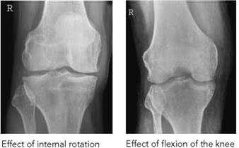
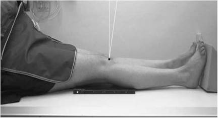
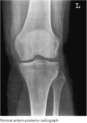
• The patient is either supine or seated on the X-ray table, with both legs extended. The affected limb is rotated to centralize the patella between the femoral condyles, and sandbags are placed against the ankle to help maintain this position.
• The cassette should be in close contact with the posterior aspect of the knee joint, with its centre level with the upper borders of the tibial condyles.
Direction and centring of the X-ray beam
• Centre 2.5 cm below the apex of the patella through the joint space, with the central ray at 90 degrees to the long axis of the tibia.
Essential image characteristics
• The patella must be centralized over the femur.
Notes
• To enable correct assessment of the joint space, the central ray must be at 90 degrees to the long axis of the tibia and, if necessary, angled slightly cranially. If the central ray is not perpendicular to the long axis of the tibia, then the anterior and posterior margins of the tibial plateau will be separated widely and assessment of the true width of the joint space will be difficult.
• If the central ray is too high, then the patella is thrown down over the joint space and the joint space appears narrower.
• If the knee joint is flexed and the patient is unable to extend the limb, then the cassette may be raised on pads to bring it as close as possible to the posterior aspect of the knee.
• In the antero-posterior projection, the patella is remote from the cassette. Although the relationship of the patella to the surrounding structures can be assessed the trabecular pattern of the femur is superimposed. Therefore, this projection is not ideal for demonstrating discrete patella bony abnormalities.

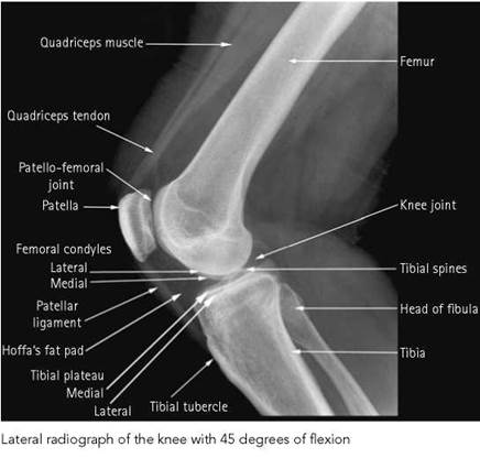
Lateral - basic
Position of patient and cassette
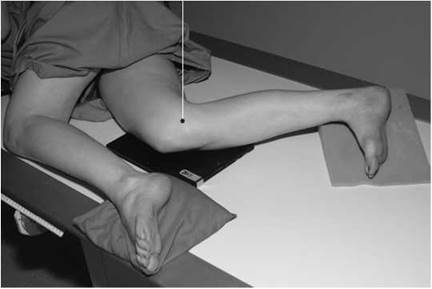
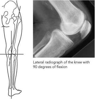
• The patient lies on the side to be examined, with the knee flexed at 45 or 90 degrees (see below).
• The other limb is brought forward in front of the one being examined and supported on a sandbag.
• A sandbag is placed under the ankle of the affected side to bring the long axis of the tibia parallel to the cassette.
• The position of the limb is now adjusted to ensure that the femoral condyles are superimposed vertically.
• The centre of the cassette is placed level with the medial tibial condyle.
Direction and centring of the X-ray beam
• Centre to the middle of the superior border of the medial tibial condyle, with the central ray at 90 degrees to the long axis of the tibia.
Essential image characteristics
• The patella should be projected clear of the femur.
• The femoral condyles should be superimposed.
• The proximal tibio-fibular joint is not clearly visible.
Notes
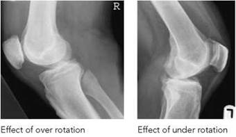
• If over-rotated, the medial femoral condyle is projected in front of the lateral condyle and the proximal tibio-fibular joint will be well demonstrated.
• If under-rotated, the medial femoral condyle is projected behind the lateral condyle and the head of the fibula is superimposed on the tibia.
• If the central ray is not at 90 degrees to the long axis of the tibia, the femoral condyles will not be superimposed.
• Flexion of the knee at 90 degrees is the most easily reproducible angle and allows assessment of any degree of patella alta or patella baja (patella riding too high or too low). With the knee flexed at 90 degrees, a patella in normal position will lie between two parallel lines drawn along the anterior and posterior surfaces of the femur.
• In patients who are unable to flex to 90 degrees, the examination should be performed at 45-degree flexion. This may permit a clearer view of the patello-femoral articulation.
Knee joint
Additional projections
Further projections are used to demonstrate fracture of the patella and the intercondylar notch. Stress views may also be taken in suspected ligamental tears.
A lateral projection of the knee and tibial tubercle may be useful in Osgood Schlatter’s disease, although this is primarily a clinical diagnosis and radiography is reserved for exclusion of other pathology in cases of doubt. Ultrasound may also be useful in this clinical situation.
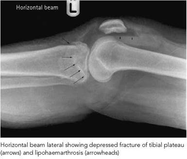
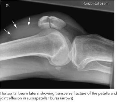
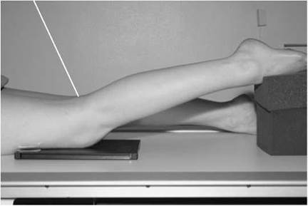
Lateral - horizontal beam
This projection replaces the conventional lateral in all cases of gross injury and suspected fracture of the patella.
Position of patient and cassette
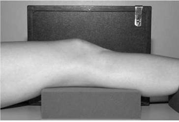
• The patient remains on the trolley/bed, with the limb gently raised and supported on pads.
• If possible, the leg may be rotated slightly to centralize the patella between the femoral condyles.
• The film is supported vertically against the medial aspect of the knee.
• The centre of the cassette is level with the upper border of the tibial condyle.
Direction and centring of the X-ray beam
• The horizontal central ray is directed to the upper border of the lateral tibial condyle, at 90 degrees to the long axis of the tibia.
Notes
• No attempt must be made to either flex or extend the knee joint.
• Additional flexion may result in fragments of a transverse patellar fracture being separated by the opposing muscle pull.
• Any rotation of the limb must be from the hip, with support given to the whole leg.
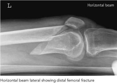
• By using a horizontal beam, fluid levels may be demonstrated, indicating lipohaemarthrosis.
Knee joint
Antero-posterior - standing projections
This projection is useful to demonstrate alignment of the femur and tibia in the investigation of valgus (bow leg) or varus (knock knee) deformity. Any such deformity will be accentuated when weight bearing, which more closely resembles the real-life situation. It is commonly requested to assess alignment prior to joint replacement, as narrowing of one side to the joint space more than the other will produce varus or valgus tilt. Both knees may be included for comparison.
Position of patient and cassette
• The cassette is supported in the chest stand.
• The patient stands with their back against the vertical Bucky, using it for support if necessary.
• The patient’s weight is distributed equally.
• The knee is rotated so that the patella lies equally between the femoral condyles.
• The limb is rotated slightly medially to compensate for the obliquity of the beam when the central ray is centred midway between the knees.
• The centre of the cassette is level with the palpable upper borders of the tibial condyles.
Direction and centring of the X-ray beam
• The horizontal beam is centred midway between the palpable upper borders of the tibial condyles.

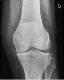
Standing antero-posterior knee radiograph showing loss of height of the medial compartment due to osteoarthritis
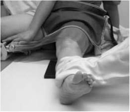
Stress projections for subluxation
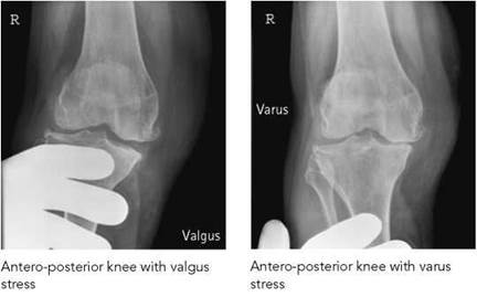
Stress projections of the knee joint are taken to show subluxation due to rupture of the collateral ligaments. Although these projections may be done in the department, they are now commonly done in theatre using a mobile image intensifier. Stress is applied to the joint by medical personnel, usually an orthopaedic surgeon.
Antero-posterior - stress
Position of patient and cassette
• The patient and cassette are positioned for the routine anteroposterior projection.
• The doctor forcibly abducts or adducts the knee, without rotating the leg.
Direction and centring of the X-ray beam
• Centre midway between the upper borders of the tibial condyles, with the central ray at 90 degrees to the long axis of the tibia.
Patella
Additional projections may be necessary to demonstrate the patella adequately.
Postero-anterior
Position of patient and cassette
• The patient lies prone on the table, with the knee slightly flexed.
• Foam pads are placed under the ankle and thigh for support.
• The limb is rotated to centralize the patella.
• The centre of the cassette is level with the crease of the knee.
Direction and centring of the X-ray beam
• Centre midway between the upper borders of the tibial condyles at the level of the crease of the knee, with the central ray at 90 degrees to the long axis of the tibia.
Notes
• The beam may have to be angled caudally to be at rightangles to the long axis of the tibia.
• The patella may be demonstrated more clearly as it is now adjacent to the image receptor and not distant from it, as in the conventional antero-posterior projection.
• Subtle abnormalities may not be detected, as the trabecular pattern of the femur will still predominate.
• This projection depends on the fitness of the patient and must not be attempted if it results in undue discomfort or if it may exacerbate the patient’s condition.
Radiological considerations
• A joint effusion is well demonstrated on the lateral projection as an ovoid density rising above the postero-superior aspect of the patella. Its significance varies according to the clinical setting. Causes include infection, haemorrhage and arthritis, but it may also be a marker of occult fracture, e.g. tibial spine or tibial plateau fracture. Lipohaemarthrosis occurs when a fracture passes into the marrow-containing medullary space. Fat (bone marrow) leaks into the joint, producing a fluid level between fat and fluid (blood) that can be seen when a horizontal beam is used.
• Fracture of the anterior tibial spine may be subtle, with demonstration requiring attention to exposure and rotation. It is important as the attachment of the anterior cruciate ligament, avulsion of which may cause debilitating instability of the knee.
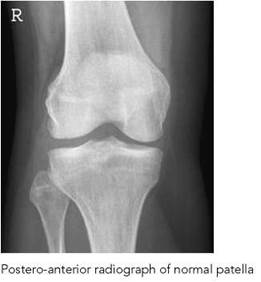
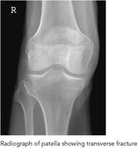
• Vertical fracture of the patella is not visible on the lateral projection and will be seen on the antero-posterior projection only if exposed properly (i.e. not underexposed). If clinically suspected, then a skyline view maybe requested.
• Tibial plateau fractures can be subtle and hard to detect, but again they are functionally very important. Good technique is the key. Full evaluation may be aided by three-dimensional CT in some cases.
• The fabella is a sesamoid bone in the tendon of medial head of gastrocnemius, behind the medial femoral condyle, and should not be confused with loose body.
• Osgood-Schlatters disease is a clinical diagnosis and does not usually require radiography for diagnosis. Ultrasound may be useful if confirmation is required. Projections of the contralateral knee should not normally be needed.
Skyline projections
The skyline projection can be used to:
• assess the retro-patellar joint space for degenerative disease;
• determine the degree of any lateral subluxation of the patella with ligament laxity;
• diagnose chondromalacia patellae;
• confirm the presence of a vertical patella fracture in acute trauma.
The optimum retro-patellar joint spacing occurs when the knee is flexed approximately 30-45 degrees. Further flexion pulls the patella into the intercondylar notch, reducing the joint spacing; as flexion increases, the patella tracks over the lateral femoral condyle. The patella moves a distance of 2 cm from full extension to full flexion.
There are three methods of achieving the skyline projection:
• conventional infero-superior;
• supero-inferior - beam directed downwards;
• infero-superior - patient prone.
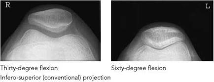
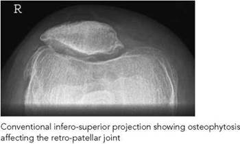
Conventional infero-superior projection
The procedure is undertaken using an 18 X 24-cm cassette.
Position of patient and cassette
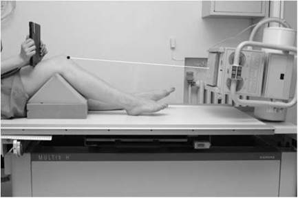
• The patient sits on the X-ray table, with the knee flexed 30-45 degrees and supported on a pad placed below the knee.
• A cassette is held by the patient against the anterior distal femur and supported using a non-opaque pad, which rests on the anterior aspect of the thigh.
Direction and centring of the X-ray beam
• The tube is lowered. Avoiding the feet, the central ray is directed cranially to pass through the apex of the patella parallel to the long axis.
• The beam should be closely collimated to the patella and femoral condyles to limit scattered radiation to the trunk and head.
Radiation protection
• Examination of the individual single knee is recommended, rather than including both knees in one exposure when both knees are requested.
• The total radiation field can be reduced, thus limiting the scattered radiation.
• A lead-rubber apron is worn for protection, with additional lead-rubber protection placed over the gonads.
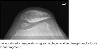
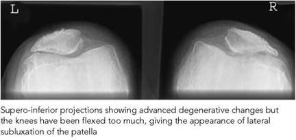
Supero-inferior
This projection has the advantage that the radiation beam is not directed towards the gonads.
Position of patient and cassette
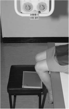
• The patient sits on the X-ray table, with the affected knee flexed over the side.
• Ideally, the leg should be flexed to 45 degrees to reflect a similar knee position to the conventional skyline projection. Too much flexion reduces the retro-patellar spacing. Sitting the patient on a cushion helps to achieve the optimum position.
• The cassette is supported horizontally on a stool at the level of the inferior tibial tuberosity border.
Direction and centring of the X-ray beam
• The vertical beam is directed to the posterior aspect of the proximal border of the patella. The central ray should be parallel to the long axis of the patella.
• The beam is collimated to the patella and femoral condyles.
Notes
• Not enough flexion will cause the tibial tuberosity to overshadow the retro-patellar joint.
• Too much flexion will cause the patella to track over the lateral femoral condyle.
Radiation protection
Radiation protection should be provided to the gonads, and the patient should lean backwards, away from the primary beam.
Knee joint
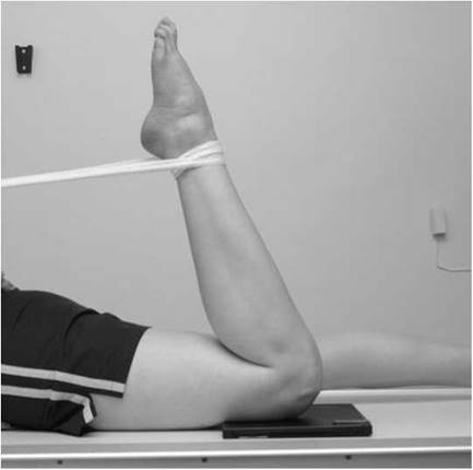
Infero-superior - patient prone
This projection has the advantage in that the primary beam is not directed towards the gonads, as is the case with the conventional infero-superior projection. However, the patient has to be able to adopt the prone position, which may not be suitable for all patients.
Position of patient and cassette
• The patient lies prone on the X-ray table, with the cassette placed under the knee joint and the knee flexed through 90 degrees.
• A bandage placed around the ankle and either tethered to a vertical support or held by the patient may prevent unnecessary movement.
Direction and centring of the X-ray beam
• Centre behind the patella, with the vertical central ray angled approximately 15 degrees towards the knee, avoiding the toes.
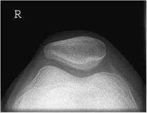
Normal infero-superior radiograph of patella, patient prone
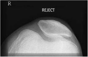
Infero-superior radiograph with insufficient flexion causing the tibia to be projected over the patella
Postero-anterior oblique
Position of patient and cassette
• The patient lies prone on the X-ray table.
• The trunk is then rotated on to each side in turn to bring either the medial or the lateral aspect of the knee at an angle of approximately 45 degrees to the cassette.
• The knee is then flexed slightly.
• A sandbag is placed under the ankle for support.
• The centre of the cassette is level with the uppermost tibial condyle.
Direction and centring of the X-ray beam
• The vertical central ray is directed to the uppermost tibial condyle.
Antero-posterior oblique
Position of patient and cassette
• The patient lies supine on the X-ray table.
• The trunk is then rotated to allow rotation of the affected limb either medially or laterally through 45 degrees.
• The knee is flexed slightly.
• A sandbag is placed under the ankle for support.
• The centre of the cassette is level with the upper border of the uppermost tibial condyle.
Direction and centring of the X-ray beam
• The vertical central ray is directed to the middle of the uppermost tibial condyle.
Notes
• These projections may be taken in addition to the basic images to show each half of the patella clear of the femur.
• The choice of either postero-anterior oblique or anteroposterior oblique is dependent upon the condition of the patient. The postero-anterior projection will give a better quality image by placing the patella in closer proximity to the cassette.
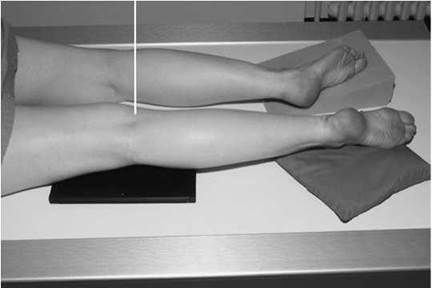
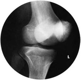
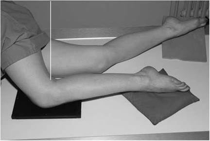
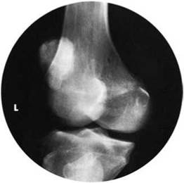
Knee joint
Intercondylar notch (tunnel)
This projection is taken to demonstrate loose bodies within the knee joint. A curved cassette with standard-speed intensifying screens, if available, is used to acquire the image. Curved cassettes are not available with digital imaging systems, in which case an 18 X 24 cm cassette will be used.
Position of patient and cassette
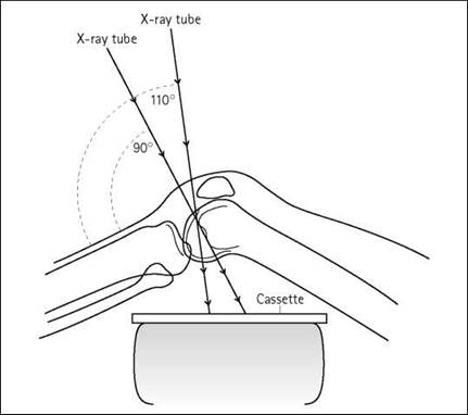
• The patient is either supine or seated on the X-ray table, with the affected knee flexed to approximately 60 degrees.
• A suitable pad is placed under the knee to help maintain the position.
• The limb is rotated to centralize the patella over the femur.
• The cassette is placed on top of the pad as close as possible to the posterior aspect of the knee and displaced towards the femur.
Direction and centring of the X-ray beam
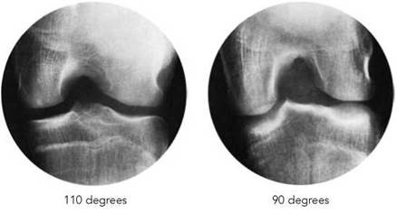
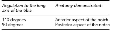
• Centre immediately below the apex of the patella, with the following angulations to demonstrate either the anterior or posterior aspects of the notch:

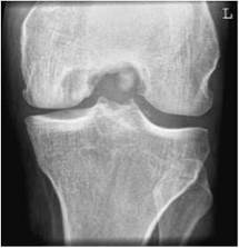
Radiograph of intercondylar notch showing loose body
Notes
• Commonly only the 90 degree angulation is used.
• This projection may be requested occasionally to demonstrate a fracture of the tibial spines, where cruciate ligaments are attached. Care must be taken when flexing the knee.
Basic projections
Two projections are taken routinely, preferably with both the knee and hip joints included on the image. If this is impossible to achieve, then the joint nearest the site of injury should be included.
A large cassette is placed in the table Bucky so that the effects of scatter are reduced. However, should only an image of the distal aspect of the femur be required, then the use of the Bucky can be eliminated in order to reduce patient dose.
Antero-posterior
Position of patient and cassette
• The patient lies supine on the X-ray table, with both legs extended.
• The affected limb is rotated to centralize the patella over the femur.
• Sandbags are placed below the knee to help maintain the position.
• The cassette is positioned in the Bucky tray immediately under the limb, adjacent to the posterior aspect of the thigh to include both the hip and the knee joints.
• Alternatively, the cassette is positioned directly under the limb, against the posterior aspect of the thigh to include the knee joint.
Direction and centring of the X-ray beam
• Centre to the middle of the cassette, with the vertical central ray at 90 degrees to an imaginary line joining both femoral condyles.
Notes
• In cases of suspected fracture, the limb must not be rotated.
• If both joints are not included on one film, then a single anteroposterior projection of the joint distal to the fracture site must be taken. This ensures that no fracture is missed and allows assessment of any rotation at the fracture site.
• Remember that the divergent beam will project the hip cranially and the knee caudally, and therefore care must be taken when positioning the cassette to ensure that the joint will be on the top/bottom of the film.
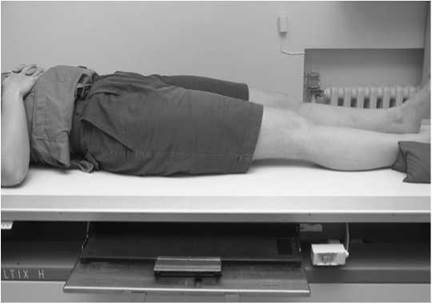
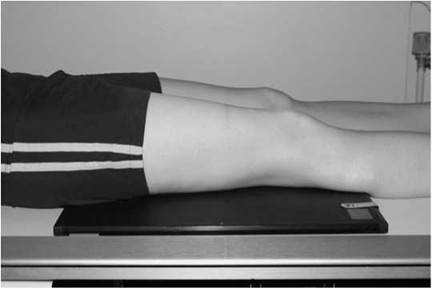
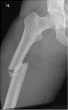
Antero-posterior radiograph of femur, hip down, showing fracture of upper femoral shaft
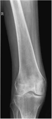
Antero-posterior radiograph of normal femur, knee up
Lateral - basic
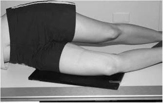
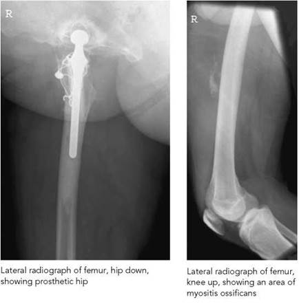
Position of patient and cassette
• From the antero-posterior position, the patient rotates on to the affected side, and the knee is slightly flexed.
• The pelvis is rotated backwards to separate the thighs.
• The position of the limb is then adjusted to vertically superimpose the femoral condyles.
• Pads are used to support the opposite limb behind the one being examined.
• The cassette is positioned in the Bucky tray under the lateral aspect of the thigh to include the knee joint and as much of the femur as possible.
• Alternatively, the cassette is positioned directly under the limb, against the lateral aspect of the thigh, to include the knee joint.
Direction and centring of the X-ray beam
• Centre to the middle of the cassette, with the vertical central ray parallel to the imaginary line joining the femoral condyles.
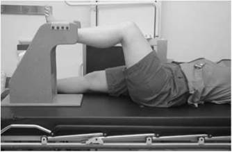
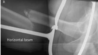
Additional projection - lateral horizontal beam
This projection replaces the conventional lateral in all cases of gross injury and suspected fracture.
Position of patient and cassette
• The patient remains on the trolley/bed. If possible, the leg may be slightly rotated to centralize the patella between the femoral condyles.
• The cassette is supported vertically against the lateral aspect of the thigh, with the lower border of the cassette level with the upper border of the tibial condyle.
• The unaffected limb is raised above the injured limb, with the knee flexed and the lower leg supported on a stool or specialized support.
Direction and centring of the X-ray beam
• Centre to the middle of the cassette, with the beam horizontal.
Note
If the injury involves only the lower two-thirds of femur, then place the cassette vertically against the medial aspect of the thigh, directing the beam from the lateral aspect of the limb to the middle of the cassette.
Radiation protection
• In all cases, the beam must be well collimated.
• Gonad protection must be applied in all non-trauma cases, as extra-focal radiation and scattered radiation will irradiate the gonads if not protected.
• In trauma cases, gonad protection is not used in the first instance as it may obscure injury. In subsequent follow-up radiographs, gonad protection must be used.
Images of both lower limbs are required to demonstrate leg alignment. This is undertaken for a variety of reasons, but predominately in adults before and after artificial joint replacement and in children for bow legs and knocked knees. The technique for children is similar to that described for leg-length measurement in the paediatric chapter (see p. 417).
In adults, this technique is undertaken with the patient erect and therefore weight bearing, and is described below for both conventional film/screen and digital computed radiography (CR).
Conventional film/screen method
Assessment by conventional film/screen radiography is undertaken using a single-exposure technique using a long cassette (35 X 105 cm) fitted with graduated screens and preferably loaded with a single film (triple-fold film) and a large FFD (typically 180-200 cm). The fastest end of the screens is placed behind the hips and the slowest at the ankle joints. The cassette is mounted vertically in a special holder to facilitate radiography in the erect position. With this technique, the divergent beam will magnify the limbs; however, the degree of inaccuracy is considered surgically insignificant and is not a factor when assessing the limbs for alignment (see Section 14, pp. 417-418, for further information).
Position of patient and cassette
• The patient stands on a low step, with the posterior aspect of the legs against the long cassette. The arms are folded across the chest. The anterior superior iliac spines should be equidistant from the cassette. The medial sagittal plane should be vertical and coincident with the central longitudinal axis of the cassette.
• The legs should be, as far as possible, in a similar relationship to the pelvis, with the feet separated so that the distance between the ankle joints is similar to the distance between the hip joints and with the patella of each knee facing forward.
• Ideally, the knees and ankle joints should be in the anteroposterior position. However, if this impossible to achieve, it is more important that the knees rather than the ankle joints are placed in the antero-posterior position.
• Foam pads and sandbags are used to stabilize the legs and maintain the position. If necessary, a block may be positioned below a shortened leg to ensure that there is no pelvic tilt and that the limbs are aligned adequately.
Direction and centring of the X-ray beam
• The horizontal central ray is directed towards a point midway between the knee joints.
• The X-ray beam is collimated to include both lower limbs from hip joints to ankle joints.
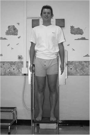

Preoperative CR image to show limb alignment
Digital computed radiography method
A special three-cassette-holding device is secured in a vertical position to allow horizontal beam radiography using a large FFD, as described for the conventional film/screen method. Using this method, three individual images of the lower limbs are acquired using one exposure. These are then 'stitched together' electronically using a special imaging software package.
Positioning of the patient and the direction and centring of the X-ray beam are similar to that described for the conventional film/screen method.
Image acquisition
Three 35 X 43-cm cassettes are inserted lengthways into the vertical cassette-holding device. This is designed to accommodate the cassettes in three separate slots, allowing for a slight overlap in the images. The holding device itself can be adjusted vertically to accommodate patients of different heights. If a patient is small in stature, then only two cassettes may be necessary.
It is important that anatomical markers are secured on to the front of the vertical cassette-holding device and placed in such a way that they are visible on each individual image. A minimum of three is recommended to distinguish between right and left limbs.
The X-ray beam is collimated to the whole area of interest from hips to ankles. The central ray is angled two to three degrees caudally to assist the stitching software.
Image analysis
Following the exposure, the cassettes are carefully identified and presented for image reading, after which post-processing of the images is undertaken to correct for differences in anatomical thicknesses. The three images are then 'stitched' together following the manufacturer's protocol to produce one full-length image. This final image is correctly windowed and annotated.
An assessment of leg alignment can then be undertaken using various post-processing tools. One technique involves drawing a line along the femur from mid-femoral head to mid-femoral condyles and a line along the length of the tibia from mid-ankle joint to mid-knee joint, which is then extended. The angle intersecting the femoral line to a continuation of the tibial line is then measured. This angle should normally be less than three degrees. Alternatively, a line (the mechanical axis) can be drawn from the mid-femoral head to midpoint of the ankle; this should pass through the centre of the knee. Deflexion of the mechanical axis can be measured and the angle derived from (m/3 + 1) degrees, where m is the deflection measured in millimetres.
Radiological considerations
The image must demonstrate the endpoints of the mechanical axis clearly, i.e. all three joints (hip, knee and ankle) must be exposed correctly and both legs must be in correct neutral anatomical position, with the patella facing forward and symmetrical.
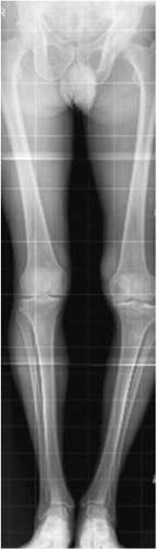
Limb alignment on CR showing genu varus secondary to osteoarthritis of the knee. This can cause difficulty fitting the whole of the limbs onto one image

Limb alignment on CR image following total knee replacement (same patient as radiograph on p. 138)