Recommended projections
|
Hip joint |
Fractured proximal end of femur |
Antero-posterior - both hips (basic) Lateral neck of femur (basic) Lateral - single hip (alternative 1 projection) Lateral - modified (alternative 2 projection) |
|
Dislocation |
Antero-posterior - both hips (basic) Antero-posterior - single hip (post-reduction) Lateral neck of femur (basic) |
|
|
Fractured acetabulum |
Antero-posterior - both hips (basic) Lateral neck of femur (basic) Posterior oblique Anterior oblique (Judet’s projection) |
|
|
Other pathology |
Antero-posterior - both hips (basic) Other projections on request |
|
|
Paediatric disorders: - Development dysplasia (DDH/CDH) - Irritable hips - Postoperative for slipped epiphysis - Trauma |
See Section 14 |
|
|
Pelvis |
Fractures and pathology |
Antero-posterior - both hips (basic) Posterior oblique (basic) Posterior oblique (alternate) Lateral |
|
Subluxation of the symphysis pubis |
Antero-posterior - erect |
|
|
Sacro-iliac joints |
Pathology |
Postero-anterior (basic) Antero-posterior Posterior obliques on request |
Anatomy and image appearances

Antero-posterior projection of pelvis

Lateral projection of pelvis

Antero-posterior projection of hip


True lateral projection of hip (neck of femur)
Introduction
The hip joint is a ball-and-socket joint in which the smooth, almost spherical head of the femur articulates with the acetabulum, which is formed by the three parts of the innominate bone.
The proximal aspect of the femur consists of the head, neck and greater and lesser trochanters. The neck lies at an angle of approximately 130 degrees with the shaft and is angulated anteriorly approximately 130 degrees when articulated normally with the acetabulum (Rogers, 2002).
The annotated images on p. 144 illustrate the anatomical references used in the text.
Two principal groups of trabeculae exist within the femoral head and neck. The trabecular pattern is more obvious in the elderly, and subtle fractures can cause these pattern lines to become distorted.
The pelvis is formed by the two innominate bones and the sacrum (the innominate bones are themselves formed from the ilium, ischium and pubis). It provides a protective girdle for the pelvic organs and supports the lower limbs. The innominate bones articulate anteriorly at the symphysis pubis and posteriorly with the sacrum at the sacro-iliac joints. As the pelvis is a ring of bone with only slightly moveable joints, bony trauma to one side can result in a corresponding injury to the opposite side.
There are several bony prominences in the pelvic region, which serve as important surface landmarks in radiography. These are:
• the symphysis pubis, upper border: anterior to the bladder, and aligned to the coccyx;
• the anterior superior iliac spine (ASIS): second sacral segment;
• the iliac crests: L4/5; bifurcation of the aorta;
• the posterior superior iliac spines: L5/S1; sacro-iliac joints.
There are also several anatomical radiographic lines that can be used to assess the integrity of the pelvis and hips in trauma:
• ‘Shenton’s line’: a line following the curve of the lower border of the superior pubic ramus and the inferior border of the femoral neck. The shape of the curves on both sides of the pelvis should be the same in the absence of an acute bony injury.
• ‘Teardrop’ sign: medial wall of the acetabulum.
• Ilio-pubic line: anterior column of the acetabulum.
• Ilio-ischial line: posterior column of the acetabulum.


Introduction (contd)
Posture
When the patient is supine, the pelvic brim is tilted according to the degree of angulation at the L5/S1 junction. This results in considerable variation in image appearance. A pronounced lordosis in the lower back can cause the obturator foramen to appear very elliptical and the symphysis pubis to be foreshortened. A small pad placed under the knees can reduce this lordosis and improve the image appearance.
This increased L5/S1 angulation in females when compared with the male pelvis contributes to the differing image appearance.
Subject type
There is a variable difference in the breadth and depth of the pelvis, according to subject type and sex, as seen in the images. The male pelvis is narrower but has greater depth. Careful positioning is often required to include the full width of a female pelvis in the image.
Radiation protection
Protection of the gonads from unnecessary X-radiation is an important factor when examining the hip joints, upper femora, pelvis and lower lumbar vertebrae. Exposure of the patient to X-radiation should be made in accordance with the as low as reasonably practicable (ALARP) principle and, in the UK, Ionising Radiations (Medical Exposure) Regulations (IRMER) 2000.
Primary lead protection should be applied to the gonads of patients from infancy to middle-age, as appropriate. It is not recommended for initial examinations, however, when its use may obscure anatomical information.


Position of limb Anatomical appearance
Neutral - long axis of foot vertical Femoral neck oblique
Lesser trochanter just visible
Internal rotation Femoral neck elongated and lying parallel to the cassette Lesser trochanter obscured by shaft of femur
External rotation Femoral neck foreshortened
Lesser trochanter clearly visible


Different positions of the lower limb result in different anatomical projections of the hip joint. The head of the femur lies anterior to the trochanteric bone of the femur when articulating normally with the acetabulum. There is an approximate angulation anteriorly of 125-130 degrees, which is best appreciated on the true lateral projection of the hip (Rogers, 2002).
Internal rotation of the hip joint by approximately 50 degrees will bring the neck of the femur parallel to the cassette and the head and trochanteric bone on the same level.
In abnormal conditions of the hip joint, the position of the foot is a significant clue to the type of injury sustained. Displaced fractures involving the neck and trochanteric region will cause external rotation and usually foreshortening of the affected leg.


Hip joint, upper third of femur and pelvis
Antero-posterior - pelvis (basic projection) and both hips (basic projection)
The antero-posterior projection is a general image used as a first assessment of the pelvic bones and hip joints. The position of the patient is identical for imaging both the hips and the pelvis, but the centring of the beam may differ. For the hip joints and upper femora, the centring may be more inferior, e.g. in trauma cases.
The antero-posterior image allows a comparison of both hips to be made; in trauma cases, it ensures that a fracture to the distal pelvis is not missed, e.g. a fractured pubic ramus.
In cases of suspected fracture of the hip, the injured limb is commonly externally rotated and must not be moved. If possible, the opposite limb should be externally rotated to the same degree of rotation so that a more accurate comparison can be made.
Position of patient and cassette
• The patient lies supine and symmetrical on the X-ray table, with the median sagittal plane perpendicular to the tabletop.
• The midline of the patient must coincide with the centred primary beam and table Bucky mechanism.
• If the patient remains on a trolley, ideally they should be positioned down the midline and adjusted to achieve an optimum projection dependent on their degree of mobility.
• To avoid pelvic rotation, the anterior superior iliac spines must be equidistant from the tabletop. A non-opaque pad placed under a buttock can be used to make the pelvis level. The coronal plane should now be parallel to the tabletop.
• The limbs are slightly abducted and internally rotated to bring the femoral necks parallel to the cassette.
• Sandbags and pads are placed against the ankle region to help maintain this position.
Direction and centring of the X-ray beam
• Centre in the midline, with a vertical central beam.
• The centre of the cassette is placed midway between the upper border of the symphysis pubis and anterior superior iliac spine for the whole of the pelvis and proximal femora. The upper edge of the cassette should be 5 cm above the upper border of the iliac crest to compensate for the divergent beam and to ensure that the whole of the bony pelvis is included.
• The centre of the cassette is placed level with the upper border of the symphysis pubis for the hips and upper femora.


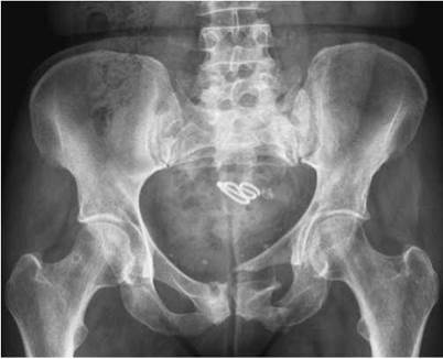
Antero-posterior pelvis showing fracture of ischium and pubis with disruption of Shenton's line. Associated fracture of the left side of the sacrum

Antero-posterior radiograph showing a subcapital fracture of the neck of the left femur

Antero-posterior radiograph of pelvis showing posterior dislocation of the left hip
Antero-posterior - pelvis (basic projection) and both hips (basic projection)
Essential image characteristics
• For the basic projection of both hips, both trochanters and the upper third of the femora must be visible on the image.
• For the basic pelvis projection, both iliac crests and proximal femora, including the lesser trochanters, should be visible on the image.
• No rotation. The iliac bones should be of equal size and the obturator foramina the same size and shape.
• It should be possible to identify Shenton's line, which forms a continuous curve between the lesser trochanter, femoral neck and lower border of the symphysis pubis.
• The optical density, ideally, should be similar throughout the bones of the pelvis and the proximal femora. If the kVp is too low and the mAs is too high, then the supero-lateral part of the ilia and the greater trochanters may not be visualized, particularly in slender patients.
• The image contrast must also allow visualization of the trabecular patterns in the femoral necks. Using compression on appropriate patients, who have excess soft tissue overlying their pelvic bones, can improve image contrast.
• No artefacts from clothing should be visible.
Notes
• Internal rotation of the limb compensates for the X-ray beam divergence when centring in the midline. The resultant image will show both greater and lesser trochanters.
• Patient breathing to blur out overlying structures can be used to diminish obvious bowel shadows over the sacrum and iliac bones.
Radiation protection
• At the first clinic visit and in trauma cases, it is normal practice to not apply gonad protection, which may obscure the pelvic bones and result in missed information. In follow-up visits, gonad protection must be used and must be positioned carefully to avoid obscuring the region of interest resulting in an unnecessary repeat radiograph.
• The primary beam should be optimally collimated to the size of the cassette. Ideally, evidence of collimation should be visible on the image.
• The correct use of automatic exposure control (AEC) reduces the number of repeats due to poor choice of exposure factors.
• Exposure factors or dose-area product (DAP) readings should be recorded.
Hip joint and upper third of femur
Antero-posterior - single hip (basic)
Position of patient and cassette
The patient is positioned as described for the basic pelvis and basic bilateral hip projections.
• The patient lies supine and symmetrical on the X-ray table, with the median sagittal plane perpendicular to the tabletop.
• To avoid pelvic rotation, the anterior superior iliac spines must be equidistant from the tabletop.
• The affected limb is internally rotated to bring the neck of the femur parallel to the tabletop, and is then supported by sandbags.
Direction and centring of the X-ray beam
• The vertical central ray is directed 2.5 cm distally along the perpendicular bisector of a line joining the anterior superior iliac spine and the symphysis pubis over the femoral pulse.
• The primary beam should be collimated to the area under examination and gonad protection applied where appropriate.

Notes
• The image must include the upper third of the femur. When taken to show the positioning and integrity of an arthroplasty, the whole length of the prosthesis, including the cement, must be visualized.
• Together with the oblique lateral projection, this is used for checking internal fixations following a fracture.
• If too high an mAs is used, the optical density around the greater trochanter may be too great for adequate visualization, particularly in very slender patients.


• Over-rotating the limb internally will bring the greater trochanter into profile. This may be a useful supplementary projection for a suspected avulsion fracture to this bone.
This projection demonstrates the upper third of the femur in the lateral position and the relationship between the head of the femur and the acetabulum. The posterior rim of the acetabulum is shown.

Normal posterior oblique projection of hip

Posterior oblique projection showing position of Garden screws
Posterior oblique (commonly known as Lauenstein's projection)
Position of patient and cassette
• The patient lies supine on the X-ray table, with the legs extended. The median sagittal plane coincides with the long axis of the table Bucky.
• The patient rotates through 45 degrees on to the affected side, with the hip abducted 45 degrees and flexed 45 degrees, and is supported in this position by non-opaque pads.
• The knee is flexed to bring the lateral aspect of the thigh into contact with the tabletop. The knee falls into a lateral position.
• The opposite limb is raised and supported behind the limb being examined.
• A 24 X 30-cm cassette is used and placed longitudinally and possibly obliquely in the Bucky tray.
• The cassette is centred at the level of the femoral pulse in the groin and should include the upper third of the femur. The upper border of the cassette should be level with the anterior superior iliac spine.
Direction and centring of the X-ray beam
• Centre to the femoral pulse in the groin of the affected side, with the central ray perpendicular to the cassette.
• The long axis of the primary beam is adjusted by turning the light beam diaphragm (LBD) to coincide with the long axis of the femur.
• The primary beam needs to be collimated to the area under examination.
Notes
• If the unaffected side is raised greater than 45 degrees, then the superior pubic ramus may be superimposed on the acetabulum.
• The shaft of the femur will be positioned at 45 degrees to the long axis of the body.
Radiological considerations
• This projection should not be used for the primary investigation of suspected fracture. A full antero-posterior projection of the pelvis is required for that purpose to assess other bony pelvic injuries.
• The patient requires a degree of mobility to be positioned satisfactorily and should not experience any great discomfort in maintaining the position.
• Used with the antero-posterior projection, it shows the satisfactory position of internal fixation pins and plates.
• The whole of the acetabular rim can be assessed when this image is used in conjunction with the anterior oblique projection (Judet's projection).
True lateral - neck of femur (basic)
This projection is used routinely in all cases of suspected fracture of the neck of femur. It is commonly carried out with the patient remaining on a stretcher, as it is not advisable to move patients with a clinical suspicion of a fracture (affected foot in external rotation, foreshortening of the limb and pain when moving). Patients who sustain a fracture of the hip are often elderly and can be quite frail. It is common practice for these patients to be ‘fast-tracked’ through Casualty and for them to have received some pain relief. Care and consideration for their dignity is necessary during the examination.
Either a 24 X 30-cm grid cassette, a cassette and stationary grid, or an erect Bucky and AEC can be used. An air-gap technique, with or without a filter, can also be used.
Position of patient and cassette
• The patient lies supine on the stretcher or X-ray table.
• The legs are extended and the pelvis adjusted to make the median sagittal plane perpendicular to the tabletop. This may not always be possible if the patient is in great pain.
• If the patient is very slender, it may be necessary to place a non-opaque pad under the buttocks so that the whole of the affected hip can be included in the image.
• The grid cassette is positioned vertically, with the shorter edge pressed firmly against the waist, just above the iliac crest.
• The longitudinal axis of the cassette should be parallel to the neck of femur. This can be approximated by placing a 45-degree foam pad between the front of the cassette and the lateral aspect of the pelvis.
• The cassette is supported in this position by sandbags or a special cassette holder attached to the table.
• The unaffected limb is then raised until the thigh is vertical, with the knee flexed. This position is maintained by supporting the lower leg on a stool or specialized equipment.


Lateral projection of hip showing subcapital fracture of neck and femur

Example of filter in place on light beam diaphragm
Direction and centring of the X-ray beam
• Centre through the affected groin, midway between the femoral pulse and the palpable prominence of the greater trochanter, with the central ray directed horizontally and at right-angles to the cassette. The central beam should be adjusted vertically to pass in line with the femoral neck and should be collimated closely to the area to improve the image contrast.
Notes
• If the erect Bucky is used, then the stretcher is turned so that its long axis makes an angle of 45 degrees with the Bucky. The neck of the femur is now parallel with the cassette placed in the Bucky. The middle AEC chamber is positioned in line with the femoral neck, which will mean an air gap exists between the patient and the erect Bucky. The resultant magnification can be compensated for by increasing the
focus-to-film distance (FFD). The air gap improves the image contrast.
• In trauma cases, when a fracture is suspected, the limb is often externally rotated. On no account should the limb be rotated from this position. The antero-posterior and lateral projections are taken with the limb in that position.
• A relatively high kVp (e.g. 100 kVp) is necessary to penetrate the thigh without blackening the trochanteric region. Using a filter improves the overall optical density.
• Loss of bony resolution can occur when using a grid cassette or stationary grid and cassette due to the X-ray beam not being aligned correctly to the grid lines.
Radiological considerations
This projection is routinely used for suspected neck of femur fracture. It is similarly invaluable for assessment of suspected slipped upper femoral epiphysis, and fracture of the acetabulum.
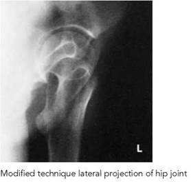
Lateral - single hip (alternative projections) modification of technique
These projections may be used when it is impossible either to rotate the patient on to the affected side or to elevate the unaffected limb.


Lateral oblique modified - alternative 1
Position of patient and cassette
• From the supine position, the patient is rotated through approximately 45 degrees on to the unaffected side, depending on the degree of mobility and pain.
• The trunk and limb are supported on non-opaque pads.
• If the patient is being examined on a trolley, the trolley is positioned against the vertical Bucky. If not, a grid cassette is supported vertically against the side being examined.
The cross-sectional diagram shows the position of the two hips when the pelvis is tilted, the cassette in position and the direction of the X-ray beam.
Direction and centring of the X-ray beam
• Centre to the femoral pulse on the side being examined, with the central ray directed horizontally and at right-angles to the cassette or vertical Bucky.
• It may be necessary to use a combination of patient rotation and inferior angulation of the central beam to achieve a diagnostic image.
• Collimate the beam to the area under examination.
Lateral modified - alternative 2
This projection is used if both limbs are injured or abducted and in a plaster cast, and the patient cannot be moved from the supine position.
Position of patient and cassette
• The patient remains supine.
• The cassette is positioned vertically against the lateral aspect of the affected hip and centred at the level of the femoral pulse.
• The cassette is tilted backwards through 25 degrees and placed a little under the affected buttock. It is supported using pads and sandbags.
The cross-sectional diagram shows the relationship between the tube and cassette about the affected hip, enabling the two sides to be separated.
Direction and centring of the X-ray beam
• Centre to the femoral pulse, with the central ray tilted 25 degrees vertically downwards from the horizontal and at right-angles to the cassette.
• Collimate the beam to the area under examination.
Lateral - both hips ('frog's legs position')
Radiography of the hip in children is discussed in detail in Chapter 14.
When there is freedom of movement, both hips can be exposed simultaneously for a general lateral projection of the femoral necks and heads. The resultant lateral hip image is similar to that obtained through the oblique lateral projection (Lauenstein's) described previously (p. 151).
This projection may be used in addition to the basic anteroposterior of both hips when comparison of both hips is required. This may apply in children, e.g. when diagnosing osteochondritis of the capital epiphysis (Perthes' disease). The position of the patient is often referred to as the 'frog' position.
Gonad-protection devices must be positioned correctly and secured firmly.
Depending on the age and size of the patient, either a 43 X 35-cm or a 30 X 40-cm cassette is placed horizontally in the Bucky tray.
Position of patient and cassette
• The patient lies supine on the X-ray table, with the anterior superior iliac spines equidistant from the tabletop to avoid rotation of the pelvis.
• The median sagittal plane is perpendicular to the table and coincident with the centre of the table Bucky mechanism.
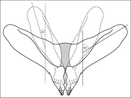
• The hips and knees are flexed and the limbs rotated laterally through approximately 60 degrees. This movement separates the knees and brings the plantar aspect of the feet in contact with each other.
• The limbs are supported in this position by pads and sandbags.
• The cassette is centred at the level of the femoral pulse to include both hip joints.
Direction and centring of the X-ray beam
• Centre in the midline at the level of the femoral pulse, with the central ray perpendicular to the cassette. Collimate to the area under examination.
Notes
• A lateral rotation of 60 degrees demonstrates the hip joints.
• A modified technique with the limbs rotated laterally through 15 degrees and the plantar aspect of the feet in contact with the tabletop demonstrates the neck of femur.
• If the patient is unable to achieve 60-degree rotation, it is important to apply the same degree of rotation to both limbs without losing symmetry.
• In very young children, a Bucky grid is not required. The child may be placed directly on to the X-ray cassette.


Normal radiograph showing both hips in lateral projection (frog legs)
Radiation protection
Gonad protection must be applied correctly and secured firmly in position.


Judet's projection of hip showing a central fracture of the acetabulum
Anterior oblique (Judet's projection)
This projection may be used to assess the acetabulum when a fracture is suspected. Although the acetabulum is seen on the anteroposterior pelvis, the anterior and posterior rims are superimposed over the head of the femur and the ischium. If the patient is immobile or in pain, then a reverse Judet's projection is taken.
Judet's projection demonstrates the anterior rim of the acetabulum, with the patient prone.
A posterior oblique projection (Lauenstein's projection) shows the posterior rim of the acetabulum, with the patient supine.
Position of patient and cassette
• The patient lies prone on the X-ray table.
• The trunk is then rotated approximately 45 degrees on to the unaffected side and the affected side is raised and supported on non-opaque pads.
• In this position, the rim of the acetabulum nearest the tabletop is approximately parallel to the cassette.
• A 24 X 30-cm cassette is placed longitudinally in the Bucky tray.
Direction and centring of the X-ray beam
• Centre just distal to the coccyx, with the central beam directed 12 degrees towards the head. Collimate to the affected area.
Posterior oblique (reverse Judet's projection)
Position of patient and cassette
• The patient lies supine on the X-ray table.
• The affected side is raised approximately 45 degrees and supported on non-opaque pads.
Direction and centring of the X-ray beam
• Centre to the femoral pulse on the raised side, with the central ray directed 12 degrees towards the feet.
• The cassette is centred at the level of the femoral pulse and collimated to the area under examination.
Notes
• It is necessary in trauma cases to adequately demonstrate fractures of the pelvis and acetabulum, as there is a high incident of damage to the surrounding anatomy (lower urinary tract, blood vessels, nerves). These fractures can be classified as stable/unstable depending on the stability of the bony fragments.
• Computed tomography (CT) scanning is used to assess the position of intra-articular bony fragments and soft-tissue injuries.
Ilium
Although the ilium is seen on the basic pelvic projection, an oblique projection may be necessary to show the entire bone. The procedure is undertaken with the patient supine for bony trauma; however, it may not be possible to turn a badly injured patient into this position.
The posterior oblique shows the iliac wing, fossa, ischium ischial spine, sciatic notches and acetabulum. It is a similar projection to that already described for the hip and upper femora (p. 151), but with less patient rotation and centred more superiorly.

Posterior oblique - basic projection
Position of patient and cassette
• The patient lies supine on the X-ray table and is positioned for a basic antero-posterior pelvic projection.
• From this position, the patient is rotated approximately 40 degrees on to the affected side; the unaffected side is raised and supported.
• Both hips and knees are flexed and the raised limb is supported on a pad.
• The iliac fossa is now parallel to the cassette.
• A 24 X 30-cm cassette is placed crossways in the Bucky tray, with the top margin 5 cm above the iliac crest.
Direction and centring of the X-ray beam
• Centre midway between the anterior superior iliac spine of the affected side and the midline of the pelvis, with the vertical central ray perpendicular to the film.

Normal posterior oblique projection of ilium
Posterior oblique (alternate)
This is an uncommon projection that can be used when additional information is required regarding the posterior aspect of the iliac bone.
Position of patient and cassette
• The patient lies supine on the X-ray table.
• From this position, the patient is rotated approximately 45 degrees on to the unaffected side, with the affected side raised and supported.
• A 24 X 30-cm cassette is placed longitudinally in the Bucky tray 5 cm above the iliac crest.
Direction and centring of the X-ray beam
• The vertical central ray is directed to the anterior superior iliac spine on the side being examined.


Normal posterior oblique (alternate) projection of ilium
Lateral

Lateral erect radiograph of pelvis at full term of pregnancy (pelvimetry)
The patient may be examined in the erect, lateral decubitus or supine position.
The projection is uncommon for general imaging, as it will deliver a high radiation dose for limited diagnostic value. It may be used as part of a specific pelvimetry series for assessing the pelvic inlet and outlet during pregnancy, but this is now rarely practiced. For assessment of major pelvic trauma, CT is usually the preferred option.
The erect projection only is described.
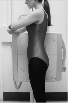
Position of patient and cassette (erect position)
• The patient stands with either side in contact with the vertical Bucky, which is adjusted vertically to the pelvic level.
• To ensure that the patient's stance is firm, the feet are separated.
• The median sagittal plane is parallel and the coronal plane is perpendicular to the image receptor.
• A careful check should be made to ensure that the vertebral column is parallel to the image receptor and that the coronal plane is at right angles to the image receptor. The latter may be assessed by palpating either the anterior or posterior superior iliac spines and rotating the patient as necessary so that an imaginary line joining the two sides is at right angles to the image receptor.
• The arms are folded across the chest and the arm nearest the Bucky can rest on top of the Bucky for support.
Direction and centring of the X-ray beam
• A cassette of suitable size is placed horizontally in the vertical Bucky.
• The central ray is directed horizontally to a depression immediately superior to the greater trochanter and collimated to include the symphysis pubis, ischium and the iliac crests.
Symphysis pubis
This projection may be done to demonstrate postpartum widening of the symphysis pubis, although this is rarely clinically relevant. Non-weight-bearing views may show subluxation of the symphisis pubis. Alternatively, two antero-posterior radiographs may be obtained in the erect position, with the patient weight-bearing on alternate feet. The dose implications of this study must be assessed against the likely benefit.
Antero-posterior - erect
Position of patient and cassette
• The patient stands with the posterior aspect of the trunk against the vertical Bucky.
• The arms are folded across the chest with the feet separated, so that the patient can comfortably adopt a standing position on one foot, and then the other.
• The anterior superior iliac spines should be equidistant from the image receptor, with the median sagittal plane perpendicular to the vertical central line of Bucky.
• The vertical Bucky is adjusted so that the horizontal central line is at the same level as the symphysis pubis.
• For the single projection a 24 X 30-cm cassette is exposed with the weight equally distributed on both feet.
• For the weight bearing projection, a 24 X 30-cm cassette is exposed, with the full weight of the body on one limb. A second cassette is then exposed with the weight on the opposite limb.
Direction and centring of the X-ray beam
• Centre to the midline at the level of the symphysis pubis, with the horizontal central ray perpendicular to the image receptor.


Antero-posterior projection of symphysis pubis showing widening of the symphysis
Postero-anterior

The sacrum is situated posteriorly between the two iliac bones, the adjacent surfaces forming the sacro-iliac joints. These joint surfaces are oblique in direction, sloping backward, inward and downward.
In the prone position, the oblique rays coincide with the direction of the joints.
The postero-anterior projection demonstrates the joints more effectively than the antero-posterior projection. It also reduces the radiation dose to the gonads in comparison with the anteroposterior projection.
Position of patient and cassette
• The patient lies prone, with the median sagittal plane perpendicular to the tabletop.
• The posterior superior iliac spines should be equidistant from the tabletop to avoid rotation.
• The midline of the patient should coincide with the centred primary beam and the table Bucky mechanism.
• The forearms are raised and placed on the pillow.
• A 24 X 30-cm cassette is placed transversely in the Bucky tray and positioned so that the central ray passes through the centre of the cassette.
Direction and centring of the X-ray beam
• Centre in the midline at the level of the posterior superior iliac spines.
• The central ray is angled 5-15 degrees caudally from the vertical, depending on the sex of the patient. The female requires greater caudal angulation of the beam.
• The primary beam is collimated to the area of interest.


Normal postero-anterior projection of sacro-iliac joints
Antero-posterior
The antero-posterior projection shows both sacro-iliac joints on one image and can be done when the patient is unable to turn prone.
The positions of the patient and the film and the direction of the beam are the same as those described for the anteroposterior projection of the sacrum.
The sacro-iliac joints are included routinely on the anteroposterior projection of the lumbar spine in some protocols, as some pathologies can give rise to lower back pain.
Position of patient and cassette
• The patient lies supine and symmetrical on the X-ray table, with the median sagittal plane perpendicular.
• The midline of the patient must coincide with the centred primary beam and the table Bucky mechanism.
• To avoid rotation, the anterior superior iliac spines must be equidistant from the tabletop.
• A 24 X 30-cm cassette, placed transversely in the Bucky tray, is centred at a level to coincide with the central ray.
• The shoulders are raised over a pillow to eliminate the lumbar arch.
• The knees should be flexed over foam pads for comfort.
Direction and centring of the X-ray beam
• Centre in the midline at a level midway between the anterior superior iliac spines and the superior border of the symphysis pubis.
• The central ray is directed between 5 and 15 degrees cranially, depending on the sex of the patient. The female requires greater caudal angulation of the beam.
• The primary beam is collimated to the area of interest.


Normal antero-posterior projection of sacro-iliac joints

Antero-posterior oblique
Both sides are examined for comparison.
Position of patient and cassette
• The patient lies supine on the table.
• From this position, the patient is rotated 15-25 degrees on to the side not being examined.
• The anterior superior iliac spine on the raised side should lie just lateral to the posterior superior iliac spine.
• The raised side is supported with non-opaque pads placed under the trunk and the raised thigh.
• Pads may be placed between the knees for comfort.
Direction and centring of the X-ray beam
• Centre 2.5 cm medial to the anterior superior iliac spine on the raised side (the side under examination), with the central ray perpendicular to the cassette.
Note
If it is necessary to demonstrate the inferior part of the joint more clearly, the central ray is angled 15 degrees cranially and centred 2.5 cm medial to and 5 cm inferior to the anterior superior iliac spine on the side under examination (raised side).

