Recommended projections
The projections recommended below are only a guide, as practice may vary according to local departmental protocols.
|
Cervical vertebrae |
Severe trauma (patient on |
Lateral supine with horizontal beam (basic) |
|
trolley with neck brace) |
Antero-posterior supine (basic) Antero-posterior C1/2, ‘open mouth’, supine (basic) Swimmers’ lateral supine or oblique supine if C7/T1 not demonstrated (additional) Flexion and extension (additional), consultant request after initial images cleared |
|
|
Minor trauma (patient walking) |
Lateral erect (basic) Antero-posterior, erect or supine (basic) Antero-posterior C1/2, ‘open mouth’, erect or supine (basic) Swimmers’ lateral or oblique if C7/T1 not demonstrated (additional) Flexion and extension (additional), consultant request after initial images cleared |
|
|
Non-traumatic pathology |
Lateral erect (basic) Antero-posterior, erect or supine (basic) Flexion and extension (additional) Oblique erect (additional) Flexion and extension (additional) Swimmers’ lateral if cervico-thoracic region is of particular interest (additional) |
|
|
Thoracic vertebrae |
Trauma (patient on trolley) |
Lateral supine with horizontal beam (basic) Antero-posterior supine (basic) |
|
Non-traumatic pathology |
Lateral (basic) Antero-posterior supine (basic) |
|
|
Lumbar vertebrae |
Trauma (patient on trolley) |
Lateral supine with horizontal beam (basic) Antero-posterior supine (basic) |
|
Non-traumatic pathology |
Lateral (basic) Antero-posterior supine or postero-anterior (basic) Oblique (additional) Flexion and extension (additional) |
|
|
Lumbo-sacral junction |
Trauma (patient on trolley) |
Lateral supine with horizontal beam (basic) Antero-posterior supine (basic) |
|
Non-traumatic pathology |
Lateral (basic) Antero-posterior supine (basic) Oblique (additional) |
|
|
Sacrum |
Trauma |
Lateral (basic), horizontal beam if patient cannot turn Antero-posterior supine (basic) |
|
Non-traumatic pathology |
Lateral (basic) Antero-posterior (basic) See Chapter 5 |
|
|
Coccyx |
Trauma/pathology |
Projections not normally performed unless patient considered for coccyxectomy Lateral (basic), antero-posterior (basic) |
|
Scoliosis and kyphosis |
See Section 14 |

Vertebral curves
At birth, the majority of the vertebral column is curved, with its concavity facing forward. As development occurs, and the child starts to lift its head and begins to walk, additional curvatures develop with the spine in response to these activities. The anterior concavity is maintained in the thoracic and sacro-coccygeal regions, hence they are given the name primary curves. The cervical and lumbar regions become convex anteriorly. These are the secondary curves.
A knowledge of vertebral curves is important in radiography as their position with respect to the direction of the X-ray beam will determine the quality of the final image in terms of ability to make an accurate diagnosis.
Important considerations in spinal radiography
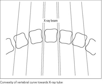
• Remember that the X-ray beam diverges from the focal spot on the anode. The X-rays are not parallel to each other.
• Ideally, the vertebral bodies will not be superimposed over one another and will be separated on the image.
• Disc spaces should be demonstrated clearly, without superimposition of vertebral bodies.
• The vertebral endplates will be parallel with the X-ray beam at a given point. This will ensure that the lateral borders are superimposed and will give the typical quadrangular appearance on the final image.
• In order to achieve the above, the concavity of the part of the spine under examination should always face the X-ray tube (see diagrams).
• The curves are variable along the area of interest, thus making it impossible to achieve separation of individual vertebra. In this instance, it may be worth considering individual exposures, with the beam angled to achieve the required degree of separation.
Vertebral levels
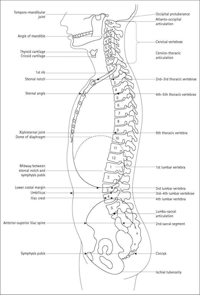
The photographs below and the diagram on the next page illustrate the surface markings of the vertebral levels, which are useful in radiographic positioning. The relative positions may vary according to the patient’s build and posture.
Useful landmarks
• The easily palpated tip of the mastoid process indicates the level of C1.
• The spinous process of C7 produces a visible protuberance on the posterior aspect of the inferior part of the neck. Below this, the spinous process of the thoracic spine can be palpated. NB: the thoracic spinous processes are directed steeply downwards, so their palpable tips will be adjacent to the vertebral body below.
• The inferior angle of the scapula indicates the level of T7 when the arms are placed by the side.
• The sternal notch lies at the junction between T2 and T3.
• T4 is indicated by the sternal angle with T9 corresponding to the xiphisternal joint, although the size of this structure is variable.
• The lower costal margin indicates L3 and is located easily. This is a very useful aid to positioning in spinal radiography.
• A line joining the most superior parts of the iliac crests indicates the level of L4, whilst the tubercle of the iliac crest discloses the location of L5.
• The anterior and posterior iliac spines lie at the level of the second sacral vertebra.
• The coccyx can be palpated between the buttocks and lies at the level of the symphysis pubis.

Cervical vertebrae
Basic projections
Many centres perform an antero-posterior and a lateral projection, with the addition of a further image to demonstrate the C1/2 region if the patient has a history of trauma.
18 X 24-cm cassettes are employed routinely, but 24 X 30-cm cassettes are often used in difficult cases.
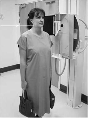
Lateral erect
Position of patient and cassette
• The patient stands or sits with either shoulder against the cassette.
• The median sagittal plane should be adjusted such that it is parallel with the cassette.
• The head should be flexed or extended such that the angle of the mandible is not superimposed over the upper anterior cervical vertebra or the occipital bone does not obscure the posterior arch of the atlas.
• To aid immobilization, the patient should stand with the feet slightly apart and with the shoulder resting against the cassette stand.
• In order to demonstrate the lower cervical vertebra, the shoulders should be depressed, as shown in the photograph. This can be achieved by asking the patient to relax their shoulders downwards. The process can be aided by asking the patient to hold a weight in each hand (if they are capable) and making the exposure on arrested expiration.
Direction and centring of the X-ray beam
• The horizontal central ray is centred to a point vertically below the mastoid process at the level of the prominence of the thyroid cartilage.
Essential image characteristics
• The whole of the cervical spine should be included, from the atlanto-occipital joints to the top of the first thoracic vertebra.
• The mandible or occipital bone does not obscure any part of the upper vertebra.
• Angles of the mandible and the lateral portions of the floor of the posterior cranial fossa should be superimposed.
• Soft tissues of the neck should be included.
• The contrast should produce densities sufficient to demonstrate soft tissue and bony detail.


Cervical vertebrae
Lateral erect
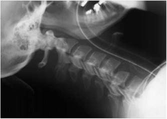
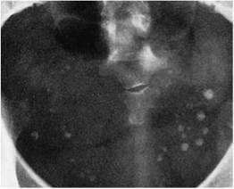
Lateral supine projection showing fracture dislocation of C5/C6
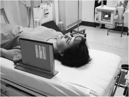
Positioning for lateral supine projection

Radiological considerations
• Atlanto-axial subluxation is seen on the lateral projection, especially in flexion (where appropriate). Care is needed in making this diagnosis in children, in whom the normal space is larger (adults <2 mm, children 3-5 mm).
• Visualization of the margins of the foramen magnum can be difficult but is necessary for diagnosis of various skull-base abnormalities, such as basilar invagination. It will be obscured by incorrect exposure or the presence of earrings.
• A secondary sign of a vertebral injury is swelling of the soft tissues anterior to the vertebral body (normal thickness is less than the depth of a normal vertebral body). This can be mimicked by flexion of the neck - always try to obtain films in the neutral position.
Common faults and remedies
• Failure to demonstrate C7/T1: if the patient cannot depress the shoulders, even when holding weights, then a swimmers’ projection should be considered.
• Care should be taken with the position of the lead name blocker. Important anatomy may easily be obscured, especially when using a small cassette.
Notes
• The large object-to-film distance (OFD) will increase geometric unsharpness. This is overcome by increasing the focus- to-film distance (FFD) to 150 cm.
• An air gap between the neck and the film eliminates the need to employ a secondary radiation grid to attenuate scatter.
Radiation protection
• Care should be taken when collimating to avoid including the eyes within the primary beam.
Lateral supine
For trauma cases, the patient’s condition usually requires the examination to be performed on a casualty trolley. The lateral cervical spine projection is taken first, without moving the patient. The resulting radiograph must be examined by a medical officer to establish whether the patient’s neck can be moved for other projections. See Section 16 for additional information.
Position of patient and cassette
• The patient will normally arrive in the supine position.
• It is vitally important for the patient to depress the shoulders (assuming no other injuries to the arms).
• The cassette can be either supported vertically or placed in the erect cassette holder, with the top of the cassette at the same level as the top of the ear.
Lateral supine (contd)
• To further depress the shoulders, one or two suitably qualified individuals can apply caudal traction to the arms. NB: refer to departmental local rules for staff working within a controlled area.
Common faults and remedies
• Failure to demonstrate C7/T1: if the patient's shoulders are depressed fully, then the application of traction will normally show half to one extra vertebra inferiorly. Should the cervical thoracic junction still remain undemonstrated, then a swimmers' lateral or oblique projections should be considered.
Radiological considerations
• This projection is part of the Advanced Trauma and Life Support (ATLS) primary screen.
• Clear demonstration of the C7/T1 junction is essential, as this is a common site of injury and is associated with major neurological morbidity. It is often not covered fully on the initial trauma screen and must always be demonstrated in the setting of trauma, by supplementary projections if necessary.

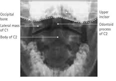
Antero-posterior - first and second cervical vertebrae (open mouth)
Position of patient and cassette
• The patient lies supine on the Bucky table or, if erect positioning is preferred, sits or stands with the posterior aspect of the head and shoulders against the vertical Bucky.
• The medial sagittal plane is adjusted to coincide with the midline of the cassette, such that it is at right-angles to the cassette.
• The neck is extended, if possible, such that a line joining the tip of the mastoid process and the inferior border of the upper incisors is at right-angles to the cassette. This will superimpose the upper incisors and the occipital bone, thus allowing clear visualization of the area of interest.
• The cassette is centred at the level of the mastoid process.
Direction and centring of the X-ray beam
• Direct the perpendicular central ray along the midline to the centre of the open mouth.
• If the patient is unable to flex the neck and attain the position described above, then the beam must be angled, typically five to ten degrees cranially or caudally, to superimpose the upper incisors on the occipital bone.
• The cassette position will have to be altered slightly to allow the image to be centred after beam angulation.

Antero-posterior - first and second cervical vertebrae (open mouth)
Essential image characteristics
• The inferior border of the upper central incisors should be superimposed over the occipital bone.
• The whole of the articulation between the atlas and the axis must be demonstrated clearly.
• Ideally, the whole of the dens, the lateral masses of the atlas and as much of the axis as possible should be included within the image.
Radiological considerations
• Fracture of the odontoid peg usually occurs across the base, below the suspensory ligament supporting the atlas. Good initial plain images are therefore essential. The base of the peg must not be obscured by any overlying bone or tooth. Failure to demonstrate the peg will lead to the need for more complex imaging. In a patient who is to have computed tomography (CT) of the head for associated trauma, scans of areas of the spine not already covered adequately are recommended in ATLS. In other patients, failure to show C1/2 either will result in the need for a CT scan for the spine alone or will lead to the patient being fully immobilized for a long period of time, with the morbidity attendant upon that.
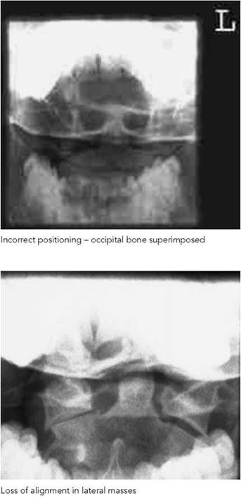
• A burst (Jefferson) fracture is seen on the antero-posterior view as a loss of alignment of the margins of the lateral masses. Rotated images make this harder to appreciate (this fracture is seen very well on CT).
Common faults and remedies
• Failure to open the mouth wide enough: the patient can be reminded to open their mouth as wide as possible just before the exposure.
• A small degree of rotation may result in superimposition of the lower molar over the lateral section of the joint space. Check for rotation during positioning.
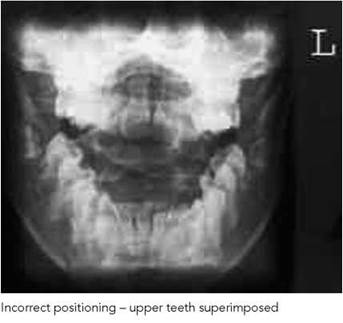
• If the front teeth are superimposed over the area of interest (top left photograph), then the image should be repeated with the chin raised or with an increased cranial angulation of the tube.
• If the occipital bone is superimposed, then the chin should be lowered or a caudal angulation should be employed.
• It is worth noting that some individuals have a very prominent maxilla. It will be very difficult to produce an image without some degree of superimposition in these cases, so an alternative projection or modality should be considered.
Antero-posterior - first and second cervical vertebrae (open mouth) (contd)
Note
A decrease in patient dose can be obtained by not using a grid. This will produce an image of lower contrast due to the increased scatter incident on the film, but it should still be of diagnostic quality. The choice of whether to use a grid will vary according to local needs and preferences.
Radiation protection
• Local protocols may state that this projection is not routinely used for degenerative disease.
Antero-posterior third to seventh vertebrae
Position of patient and cassette
• The patient lies supine on the Bucky table or, if erect positioning is preferred, sits or stands with the posterior aspect of the head and shoulders against the vertical Bucky.
• The median sagittal plane is adjusted to be at right-angles to the cassette and to coincide with the midline of the table or Bucky.
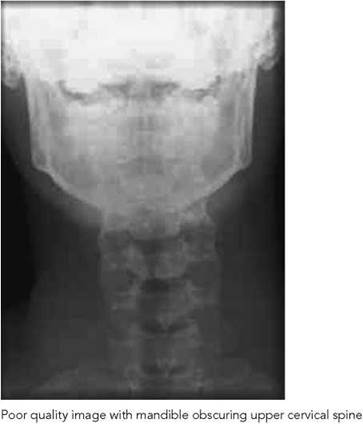
• The neck is extended (if the patient's condition will allow) so that the lower part of the jaw is cleared from the upper cervical vertebra.
• The cassette is positioned in the Bucky to coincide with the central ray. The Bucky tray will require some cranial displacement if the tube is angled.
Direction and centring of the X-ray beam
• A 5-15-degree cranial angulation is employed, such that the inferior border of the symphysis menti is superimposed over the occipital bone.
• The beam is centred in the midline towards a point just below the prominence of the thyroid cartilage through the fifth cervical vertebra.


Antero-posterior third to seventh vertebrae
Radiological considerations
• A unifacet dislocation can be diagnosed by loss of continuity of the line of spinous processes (or a line bisecting the bifid processes). This is made more difficult if the patient is rotated or the image is underexposed.
Common faults and remedies
• Failure to demonstrate the upper vertebra: an increase in the tube angle or raising the chin should provide a solution.
Notes
• Work is currently being undertaken to investigate the advantages of performing this projection postero-anteriorly. The positioning is similar to the antero-posterior projection, except that the patient faces the cassette and a 15-degree caudal angulation is applied to the tube. Indications suggest that this projection has the advantage of showing the disc spaces more clearly and substantially reducing the dose to the thyroid.
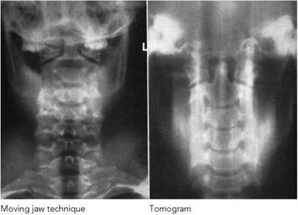
• The moving jaw technique uses auto-tomography to diffuse the image of the mandible, thus demonstrating the upper vertebra more clearly. The patient's head must be immobilized well, and an exposure time that is long enough to allow the jaw to open and close several times must be used.
• Linear tomography has also been used to demonstrate the cervical vertebra obscured by the mandible and facial bones.
Axial - upper cervical vertebra
This is a useful projection if the odontoid peg cannot be demonstrated using the open mouth projection. Remember that the
neck must not be flexed in acute injuries.
Position of patient and cassette
• The patient lies supine on the Bucky table, with the median sagittal plane coincident with the midline of the table and at right-angles to the cassette.
• The neck is extended so that that the orbito-meatal baseline is at 45 degrees to the tabletop. The head is then immobilized.
• The cassette is displaced cranially so that its centre coincides with the central ray.
Direction and centring of the X-ray beam
• The beam is angled 30 degrees cranially from the vertical and the central ray directed towards a point in the midline between the external auditory meatuses.
Essential image characteristics
• The odontoid peg will be projected over the occipital bone but clear of other confusing surrounding structures.
Notes
• Additional beam angulation may be used if the patient is wearing a rigid collar.
• Linear tomography has also been used to demonstrate this region.


Example of linear tomogram

Lateral - flexion and extension
These projections may be required, but only at the request of a medical officer, to supplement the basic projections in cases of trauma, e.g. subluxation, or pathology, e.g. rheumatoid arthritis (and often before surgery to assess movement in the neck for insertion of an endotracheal tube). The degree of movement and any change in the relationship of the cervical vertebrae can also be assessed. If an injury is suspected or is being followed up, then an experienced trauma doctor must be present to supervise flexion and extension of the neck.
Position of patient and cassette
• The patient is positioned as for the lateral basic or lateral supine projections; however, erect positioning is more convenient. The patient is asked to flex the neck and to tuck the chin in towards the chest as far as is possible.
• For the second projection, the patient is asked to extend the neck by raising the chin as far as possible.
• Immobilization can be facilitated by asking the patient to hold on to a solid object, such as the back of a chair.
• The cassette is centred to the mid-cervical region and may have to be placed transversely for the lateral in flexion, depending on the degree of movement and the cassette size used.
• If imaged supine, the neck can be flexed by placing pads under the neck. Extension of the neck can be achieved by placing pillows under the patient’s shoulders.
Direction and centring of the X-ray beam
• Direct the central ray horizontally towards the mid-cervical region (C4).
Essential image characteristics
• The final image should include all the cervical vertebra, including the atlanto-occipital joints, the spinous processes and the soft tissues of the neck.
Notes
• The large OFD will increase geometric unsharpness. This is overcome by increasing the focal film distance to 150 cm.
• An air gap between the neck and the film eliminates the need to employ a secondary radiation grid to attenuate scatter.
• Refer to local protocols for the removal of immobilization collars when undertaking these examinations.

Whiplash injury (spine in neutral position)
Cervical vertebrae
Right and left posterior oblique - erect
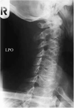
Oblique projections are requested mainly to supplement the basic projections in cases of trauma. The images demonstrate the intervertebral foramina, the relationship of the facet joints in suspected dislocation or subluxation as well as the vertebral arches. Oblique projections have also been used with certain pathologies, such as degenerative disease.
Position of patient and cassette
• The patient stands or sits with the posterior aspect of their head and shoulders against the vertical Bucky (or cassette if no grid is preferred).
• The median sagittal plane of the trunk is rotated through 45 degrees for right and left sides in turn.
• The head can be rotated so that the median sagittal plane of the head is parallel to the cassette, thus avoiding superimposition of the mandible on the vertebra.
• The cassette is centred at the prominence of the thyroid cartilage.
Direction and centring of the X-ray beam
• The beam is angled 15 degrees cranially from the horizontal and the central ray is directed to the middle of the neck on the side nearest the tube.
Essential image characteristics
• The intervertebral foramina should be demonstrated clearly.
• C1 to T1 should be included within the image.
• The mandible and the occipital bone should be clear of the vertebrae.


Radiological considerations
If this and the swimmers' projections are not successful, the patient may require more complex imaging (e.g. CT).
Notes
• Anterior oblique projections are usually undertaken on mobile patients. The position used is exactly the opposite to the posterior oblique projection, i.e. the patient faces the cassette and a 15-degree caudal angulation is used. Use of this projection will reduce the radiation dose to the thyroid.
• The foraminae demonstrated on the posterior oblique are those nearest the X-ray tube.

Right and left posterior oblique - supine
This positioning is often necessary in cases of severe injury, particularly if other basic projections have failed to demonstrate the lower cervical vertebrae.
Position of patient and cassette
• The patient remains in the supine position on the casualty trolley.
• To avoid moving the neck, the cassette should ideally be placed in the cassette tray underneath the trolley.
• If no cassette tray is available, then the cassette can be slid carefully into position without moving the patient's neck.
Direction and centring of the X-ray beam
• The beam is angled 30-45 degrees to the median sagittal plane (the degree of angulation will depend on local protocols).
• The central ray is directed towards the middle of the neck on the side nearest the tube at the level of the thyroid cartilage.
Radiological considerations
• If this and the swimmers' projections are not successful, the patient may require more complex imaging (e.g. CT).
Common faults and remedies
• Unless the equipment used allows alignment of the grid slats with the tube angle, then a grid cut-off will result.
• Grid cut-off can be prevented by not using a grid. Alternatively, the gridlines can be positioned to run transversely. This will result in suboptimal demonstration of the intervertebral foramina, but the image will be of diagnostic quality.

Cervico-thoracic vertebrae
Lateral swimmers’
In all trauma radiography, it is imperative that all of the cervical vertebrae and the cervico-thoracic junction are demonstrated. This is particularly important, as this area of the spine is particularly susceptible to injury. The superimposition of the shoulders over these vertebra and subsequent failure to produce an acceptable image is a familiar problem to all radiographers. In the majority of cases, the use of the swimmers’ lateral will produce an image that reveals the alignment of these vertebrae and provides an image suitable for diagnosis.
Position of patient and cassette
• This projection is usually carried out with the patient supine on a trauma trolley. The trolley is positioned adjacent to the vertical Bucky, with the patient’s median sagittal plane parallel with the cassette.
• The arm nearest the cassette is folded over the head, with the humerus as close to the trolley top as the patient can manage. The arm and shoulder nearest the X-ray tube are depressed as far as possible.
• The shoulders are now separated vertically.
• The Bucky should be raised or lowered, such that the line of the vertebrae should coincide with the middle of the cassette.
• This projection can also be undertaken with the patient erect, either standing or sitting or supine.
Direction and centring of the X-ray beam
• The horizontal central ray is directed to the midline of the Bucky at a level just above the shoulder remote from the cassette.
Essential image characteristics
• It is imperative to ensure that the C7/T1 junction has been included on the image. It is therefore useful to include an anatomical landmark within the image, e.g. atypical CV2. This will make it possible to count down the vertebrae and ensure that the junction has been imaged.
Radiological considerations
• See Right and left posterior oblique - supine (previous page).
Common faults and remedies
• Failure to ensure that the raised arm is as flat as possible against the stretcher may result in the head of the humerus obscuring the region of interest.
Notes
• For some patients, it may be useful to rotate the side further from the cassette sufficiently forward to separate the shoulders transversely. This positioning will produce a lateral oblique projection of the vertebrae.

• Image quality will be increased if the erect Bucky is used in preference to a stationary grid. This is due to the better scatter attenuation properties of the grid within the Bucky.


Antero-posterior - basic
Position of patient and cassette
• The patient is positioned supine on the X-ray table, with the median sagittal plane perpendicular to the tabletop and coincident with the midline of the Bucky.
• The upper edge of a cassette, which should be at least 40 cm long for an adult, should be at a level just below the prominence of the thyroid cartilage to ensure that the upper thoracic vertebrae are included.
• Make exposure on arrested inspiration. This will cause the diaphragm to move down over the upper lumbar vertebra, thus reducing the chance of a large density difference appearing on the image from superimposition of the lungs.
Direction and centring of the X-ray beam
• Direct the central ray at right-angles to the cassette and towards a point 2.5 cm below the sternal angle.
• Collimate tightly to the spine.
Essential image characteristics
• The image should include the vertebrae from C7 to L1.
• The image density should be sufficient to demonstrate bony detail for the upper as well as the thoracic lower vertebrae.
Radiological considerations
• The presence of intact pedicles is an important sign in excluding metastatic disease. Pedicles are more difficult to see on an underexposed or rotated film.
Common faults and remedies
• The cassette and beam are often centred too low, thereby excluding the upper thoracic vertebrae from the image.
• The lower vertebrae are also often not included. L1 can be identified easily by the fact that it usually will not have a rib attached to it.
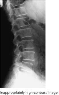
• High radiographic contrast (see below) causes high density over the upper vertebrae and low density over the lower vertebra.
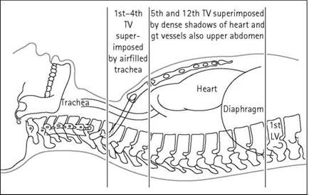
Notes
• This region has an extremely high subject contrast. This is due to the superimposition of the air-filled trachea over the upper thoracic vertebrae. This produces a relatively lucent area and a high density on the radiograph. The heart and liver superimposed over the lower thoracic vertebrae will attenuate more X-rays and yield a much lower film density.
(contd)
Antero-posterior - basic (contd)
• The radiographer can employ a number of strategies to reduce the high radiographic contrast associated with this region. The use of a relatively high kVp (80 kVp or more) will usually lower the radiographic contrast, thus demonstrating all the vertebrae within the useful density range.
• The anode heel effect can also be exploited by positioning the anode cranially and the cathode caudally.
• The use of graduated screens, wedge filters placed on the light beam diaphragm or attenuators positioned over the upper thoracic vertebrae have also proved effective in reducing the contrast.
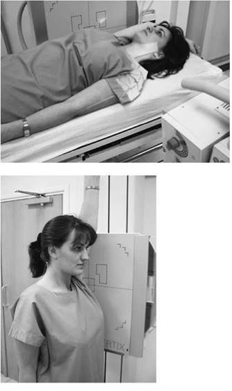
Lateral - basic
Position of patient and cassette
• Usually undertaken with the patient in the lateral decubitus position on the X-ray table, although this projection can also be performed erect.
• The median sagittal plane should be parallel to the cassette and the midline of the axilla coincident with the midline of the table or Bucky.
• The arms should be raised well above the head.
• The head can be supported with a pillow, and pads may be placed between the knees for the patient's comfort.
• The upper edge of the cassette should be at least 40 cm in length and should be positioned 3-4 cm above the spinous process of C7.
Direction and centring of the X-ray beam
• The central ray should be at right-angles to the long axis of the thoracic vertebrae. This may require a caudal angulation.
• Centre 5 cm anterior to the spinous process of T6/7. This is usually found just below the inferior angle of the scapula (assuming the arms are raised), which is easily palpable.
Essential image characteristics
• The upper two or three vertebrae may not be demonstrated due to the superimposition of the shoulders.
• Look for the absence of a rib on L1 at the lower border of the image. This will ensure that T12 has been included within the field.
• The posterior ribs should be superimposed, thus indicating that the patient was not rotated too far forwards or backwards.
• The trabeculae of the vertebrae should be clearly visible, demonstrating an absence of movement unsharpness.
• The image density should be adequate for diagnosis for both the upper and lower thoracic vertebrae. The use of a wide- latitude imaging system/technique is therefore desirable.


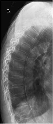

The use of autotomography (left) will prevent lung and rib shadows from obscuring the spine
Lateral - basic
Radiological considerations
• Mild endplate changes (e.g. early osteoporotic collapse or partial wedge fractures) are more difficult to see if the X-ray beam does not pass cleanly through all the disc spaces.
• 7-10 per cent of cervical spine fractures are associated with fractures of the thoracic or lumbar vertebrae, and current ATLS and Royal College of Radiologists (RCR) advice is that radiographs of the whole spine are recommended in patients with cervical spine fractures.
Common faults and remedies
• If the exposure is made on arrested inspiration, then the rib shadows will be superimposed over the vertebrae and detract from the image quality. The use of auto-tomography (see below) should resolve this problem.
Note
The vertebrae will be demonstrated optimally if auto-tomography is used to diffuse the lung and rib shadows. This involves setting a low mA (10-20 mA) and a long exposure time (3-5 s). The patient is allowed to breathe normally during the exposure.

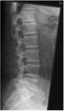
Examples of localized spine projections
Localized projections
Localized projections or tomography are requested occasionally, e.g. when following up a fracture. The centring point must be adjusted to the appropriate vertebrae. The following anterior surface markings can be used as a guide to the appropriate centring point:
• Cricoid cartilage: sixth cervical vertebra.
• Sternal notch: second to third thoracic vertebra.
• Sternal angle: lower border of fourth thoracic vertebra.
• Xiphisternal joint: ninth thoracic vertebra.
Posterior surface markings are more convenient for lateral projections. The level of the upper and middle thoracic vertebrae may be found by first palpating the prominent spinous process of the seventh cervical vertebrae and then counting the spinous processes downwards. The lower vertebrae can be identified by palpating the spinous process of the third lumbar vertebrae at the level of the lower costal margin and then counting the spinous processes upwards.
It is important to remember that the tips of the spinous processes of T5 to T10 are opposite to the bodies of the vertebrae below.
Lumbar vertebrae
Antero-posterior - basic
Position of patient and cassette
• The patient lies supine on the Bucky table, with the median sagittal plane coincident with, and at right-angles to, the midline of the table and Bucky.
• The anterior superior iliac spines should be equidistant from the tabletop.
• The hips and knees are flexed and the feet are placed with their plantar aspect on the tabletop to reduce the lumbar arch and bring the lumbar region of the vertebral column parallel with the cassette.
• The cassette should be large enough to include the lower thoracic vertebrae and the sacro-iliac joints and is centred at the level of the lower costal margin.
• The exposure should be made on arrested expiration, as the diaphragm will cause the diaphragm to move superiorly. The air within the lungs would otherwise cause a large difference in density and poor contrast between the upper and lower lumbar vertebrae.
Direction and centring of the X-ray beam
• Direct the central ray towards the midline at the level of the lower costal margin (L3).
Essential image characteristics
• The image should include from T12 down, to include all of the sacro-iliac joints.
• Rotation can be assessed by ensuring that the sacro-iliac joints are equidistant from the spine.
• The exposure used should produce a density such that bony detail can be discerned throughout the region of interest.
Radiological considerations
• The same considerations apply as to the thoracic spine.
• See p. 184.
Common faults and remedies
• The most common fault is to miss some or all of the sacroiliac joint. An additional projection of the sacro-iliac joints should be performed.
Note
For relatively fit patients, this projection can be performed with the patient in the postero-anterior position. This allows better visualization of the disc spaces and sacro-iliac joints, as the concavity of the lumbar lordosis faces the tube so the diverging beam passes directly through these structures. Although the magnification is increased, this does not seriously affect image quality.


Lateral - basic
Position of patient and cassette
• The patient lies on either side on the Bucky table. If there is any degree of scoliosis, then the most appropriate lateral position will be such that the concavity of the curve is towards the X-ray tube.
• The arms should be raised and resting on the pillow in front of the patient's head. The knees and hips are flexed for stability.
• The coronal plane running through the centre of the spine should coincide with, and be perpendicular to, the midline of the Bucky.
• Non-opaque pads may be placed under the waist and knees, as necessary, to bring the vertebral column parallel to the film.
• The cassette is centred at the level of the lower costal margin.
• The exposure should be made on arrested expiration.
• This projection can also be undertaken erect with the patient standing or sitting.
Direction and centring of the X-ray beam
• Direct the central ray at right-angles to the line of spinous processes and towards a point 7.5 cm anterior to the third lumbar spinous process at the level of the lower costal margin.
Essential image characteristics
• The image should include T12 downwards, to include the lumbar sacral junction.
• Ideally, the projection will produce a clear view through the centre of the intervertebral disc space, with individual vertebral endplates superimposed.
• The cortices at the posterior and anterior margins of the vertebral body should also be superimposed.
• The imaging factors selected must produce an image density sufficient for diagnosis from T12 to L5/S1, including the spinous processes.
Lateral - basic (contd)
Radiological considerations
• The same conditions apply as to the thoracic spine.
• Transitional vertebrae (see diagram opposite) are common at the lumbosacral junction and can make counting the level of an abnormality difficult. A sacralized L5 has a shape similar to S1, with large transverse processes, and is partially incorporated into the upper sacrum. The converse is lumbarization of S1, in which the body and appendages of S1 resemble L5 and the sacro-iliac joints are often reduced in height. These anomalies may cause errors in counting the level of an abnormality, in which case the twelfth rib and thoracic vertebra must be seen clearly to enable counting down from above. This is of particular importance when plain images are used to confirm the level of an abnormality detected on other imaging modalities, e.g. MRI.
Common faults and remedies
• High-contrast images will result in an insufficient or high image density over areas of high or low patient density, i.e. the spinous processes and L5/S1. A high kVp or the use of other wide-latitude techniques is recommended.
• The spinous processes can easily be excluded from the image as a result of overzealous collimation.
• Poor superimposition of the anterior and posterior margins of the vertebral bodies is an indication that the patient was rolled too far forward or backward during the initial positioning (i.e. mean sagittal plane not parallel to cassette).
• Failure to demonstrate a clear intervertebral disc space usually results as a consequence of the spine not being perfectly parallel with the cassette or is due to scoliosis or other patient pathology.
Note
A piece of lead rubber or other attenuator placed behind the patient will reduce scatter incident on the film. This will improve overall image quality as well as reduce the chance of automatic exposure control error.


Lateral horizontal beam
A patient with a suspected fracture to the lumbar vertebrae should not be moved from the casualty trolley without medical supervision. Similarly, the patient should not be moved into the lateral decubitus position in these circumstances. This will necessitate the use of a horizontal beam technique in order to obtain the second projection required for a complete examination. Horizontal beam techniques are discussed further in Section 16.
Position of patient and cassette
• The trauma trolley is placed adjacent to the vertical Bucky.
• Adjust the position of the trolley so that the lower costal margin of the patient coincides with the vertical central line of the Bucky and the median sagittal plane is parallel to the cassette.
• The Bucky should be raised or lowered such that the patient's mid-coronal plane is coincident with the midline of the cassette within the Bucky, along its long axis.
• If possible, the arms should be raised above the head.
Direction and centring of the X-ray beam
• Direct the horizontal central ray parallel to a line joining the anterior superior iliac spines and towards a point 7.5 cm anterior to the third lumbar spinous process at the level of the lower costal margin.
Essential image characteristics
• Refer to lateral lumbar spine (p. 183).
• Extreme care must be taken if using the automatic exposure control. The chamber selected must be directly in line with the vertebrae, otherwise an incorrect exposure will result.
• If a manual exposure is selected, them a higher exposure will be required than with a supine lateral. This is due to the effect of gravity on the internal organs, causing them to lie either side of the spine.

Lateral flexion and extension
Lateral projections in flexion and extension may be requested to demonstrate mobility and stability of the lumbar vertebrae.
Position of patient and cassette
• This projection may be performed supine, but it is most commonly performed erect with the patient seated on a stool with either side against the vertical Bucky.
• A seated position is preferred, since apparent flexion and extension of the lumbar region is less likely to be due to movement of the hip joints when using the erect position.
• The dorsal surface of the trunk should be at right-angles to the cassette and the vertebral column parallel to the cassette.
• For the first exposure the patient leans forward, flexing the lumbar region as far as possible, and grips the front of the seat to assist in maintaining the position.
• For the second exposure the patient then leans backward, extending the lumbar region as far as possible, and grips the back of the seat or another support placed behind the patient.
• The cassette is centred at the level of the lower costal margin, and the exposure is made on arrested expiration.
Direction and centring of the X-ray beam
• Direct the central ray at right-angles to the film and towards a point 7.5 cm anterior to the third lumbar spinous process at the level of the lower costal margin.
Essential image characteristics
Refer to lateral lumbar spine (p. 183). All of the area of interest must be included on both projections.
Common faults and remedies
• Extreme care must be taken if using the automatic exposure control. The chamber selected must be directly in line with the vertebrae, otherwise an incorrect exposure will result.
• If a manual exposure is selected, a higher exposure will be required than with a supine lateral. This is due to the effect of gravity on the internal organs, causing them to lie either side of the spine.
• A short exposure time is desirable, as it is difficult for the patient to remain stable.


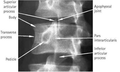
Right or left posterior oblique
These projections demonstrate the pars interarticularis and the apophyseal joints on the side nearest the cassette. Both sides are taken for comparison.
Position of patient and cassette
• The patient is positioned supine on the Bucky table and is then rotated 45 degrees to the right and left sides in turn. The patient’s arms are raised, with the hands resting on the pillow.
• The hips and knees are flexed and the patient is supported with a 45-degree foam pad placed under the trunk on the raised side.
• The cassette is centred at the lower costal margin.


Direction and centring of the X-ray beam
• Direct the vertical central ray towards the midclavicular line on the raised side at the level of the lower costal margin.
Essential image characteristics
• The degree of obliquity should be such that the posterior elements of the vertebra are aligned in such as way as to show the classic ‘Scottie dog’ appearance (see diagram).
Radiological considerations
A defect in the pars interarticularis can be congenital or due to trauma. It is a weakness in the mechanism that prevents one vertebra slipping forward on the one below (spondylolisthesis) and can be a cause of back pain. If bilateral, a spondylolisthesis is more likely. The defect appears as a ‘collar’ on the ‘Scottie dog’, hence the importance of demonstrating the ‘dog’.
Common faults and remedies
• A common error is to centre too medially, thus excluding the posterior elements of the vertebrae from the image.
Lumbo-sacral junction
Lateral
Position of patient and cassette
• The patient lies on either side on the Bucky table, with the arms raised and the hands resting on the pillow. The knees and hips are flexed slightly for stability.
• The dorsal aspect of the trunk should be at right-angles to the cassette. This can be assessed by palpating the iliac crests or the posterior superior iliac spines.
• The coronal plane running through the centre of the spine should coincide with, and be perpendicular to, the midline of the Bucky.
• The cassette is centred at the level of the fifth lumbar spinous process.
• Non-opaque pads may be placed under the waist and knees, as necessary, to bring the vertebral column parallel to the cassette.
Direction and centring of the X-ray beam
• Direct the central ray at right-angles to the lumbo-sacral region and towards a point 7.5 cm anterior to the fifth lumbar spinous process. This is found at the level of the tubercle of the iliac crest or midway between the level of the upper border of the iliac crest and the anterior superior iliac spine.
• If the patient has particularly large hips and the spine is not parallel with the tabletop, then a five-degree caudal angulation may be required to clear the joint space.
Essential image characteristics
• The area of interest should include the fifth lumbar vertebra and the first sacral segment.
• A clear joint space should be demonstrated.


Radiation protection
• This projection requires a relatively large exposure so should not be undertaken as a routine projection. The lateral lumbar spine should be evaluated and a further projection for the L5/S1 junction considered if this region is not demonstrated to a diagnostic standard.

Antero-posterior
The lumbo-sacral articulation is not always demonstrated well on the antero-posterior lumbar spine, due to the oblique direction of the articulation resulting from the lumbar lordosis. This projection may be requested to specifically demonstrate this articulation.
Position of patient and cassette
• The patient lies supine on the Bucky table, with the median sagittal plane coincident with, and perpendicular to, the midline of the Bucky.
• The anterior superior iliac spines should be equidistant from the tabletop.
• The knees can be flexed over a foam pad for comfort and to reduce the lumbar lordosis.
• The cassette is displaced cranially so that its centre coincides with the central ray.
Direction and centring of the X-ray beam
• Direct the central ray 10-20 degrees cranially from the vertical and towards the midline at the level of the anterior superior iliac spines.
• The degree of angulation of the central ray is normally greater for females than for males and will be less for a greater degree of flexion at the hips and knees.
Essential image characteristics
• The image should be collimated to include the fifth lumbar and first sacral segment.
Right or left posterior oblique
These projections demonstrate the pars interarticularis and the apophyseal joints on the side nearer the film.
Position of patient and cassette
• The patient is positioned supine on the Bucky table and is then rotated to the right and left sides in turn so that the median sagittal plane is at an angle of approximately 45 degrees to the tabletop.
• The hips and knees are flexed and the patient is supported with 45-degree foam pads placed under the trunk on the raised side.
• The cassette is displaced cranially at a level to coincide with the central ray.
Essential image characteristics
• The posterior elements of L5 should appear in the 'Scottie dog' configuration (see oblique lumbar spine, p. 187).
Common faults and remedies
• A common error is to centre too medially, thus excluding the posterior elements of the vertebrae from the image.
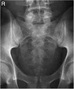
Sacrum
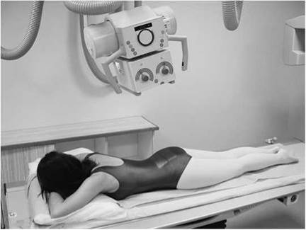
Antero-posterior/postero-anterior
The sacrum may be either imaged antero-posteriorly or postero-anteriorly. If imaged postero-anteriorly, there will be various advantages, including a lower dose to the gonads and better demonstration of the sacro-iliac joints, as the joint spaces will be more parallel with the divergent central ray. The anteroposterior position may be a more realistic option when the patient is infirm or injured and therefore would find it difficult to maintain the prone position.
Position of patient and cassette
• The patient lies supine or prone on the Bucky table, with the median sagittal plane coincident with, and at right-angles to, the midline of the Bucky.
• The anterior superior iliac spines should be equidistant from the tabletop.
• If the patient is examined supine (antero-posteriorly), the knees can be flexed over a foam pad for comfort. This will also reduce the pelvic tilt.
• The cassette is displaced cranially for antero-posterior projection, or caudally for postero-anterior projections, such that its centre coincides with the angled central ray.
Direction and centring of the X-ray beam
• Antero-posterior: direct the central ray 10-25 degrees cranially from the vertical and towards a point midway between the level of the anterior superior iliac spines and the superior border of the symphysis pubis.
• The degree of angulation of the central ray is normally greater for females than for males and will be less for a greater degree of flexion at the hips and knees.
• Postero-anterior: palpate the position of the sacrum by locating the posterior superior iliac spine and coccyx. Centre to the middle of the sacrum in the midline.
• The degree of beam angulation will depend on the pelvic tilt. Palpate the sacrum and then simply apply a caudal angulation, such that the central ray is perpendicular to the long axis of the sacrum (see photograph opposite).
Radiological considerations
• The sacrum is a thin bone. Problems with exposure can easily lead to important pathologies such as fractures and metastases being missed.


Lateral
Position of patient and cassette
• The patient lies on either side on the Bucky table, with the arms raised and the hands resting on the pillow. The knees and hips are flexed slightly for stability.
• The dorsal aspect of the trunk should be at right-angles to the cassette. This can be assessed by palpating the iliac crests or the posterior superior iliac spines. The coronal plane running through the centre of the spine should coincide with, and be perpendicular to, the midline of the Bucky.
• The cassette is centred to coincide with the central ray at the level of the midpoint of the sacrum.
Direction and centring of the X-ray beam
• Direct the central ray at right-angles to the long axis of the sacrum and towards a point in the midline of the table at a level midway between the posterior superior iliac spines and the sacro-coccygeal junction.
Radiological considerations
• Fractures are easily missed if the exposure is poor or a degree of rotation is present.
Common faults and remedies
• If using an automatic exposure control, centring too far posteriorly will result in an underexposed image.
Coccyx
Antero-posterior
Position of patient and cassette
• The patient lies supine on the Bucky table, with the median sagittal plane coincident with, and at right-angles to, the midline of the Bucky.
• The anterior superior iliac spines should be equidistant from the tabletop.
• The knees can be flexed over a foam pad for comfort and to reduce the pelvic tilt.
• The cassette is displaced caudally so that its centre coincides with the central ray.
Direction and centring of the X-ray beam
• Direct the central ray 15 degrees caudally towards a point in the midline 2.5 cm superior to the symphysis pubis.
Radiological considerations
• Anatomy of the coccyx is very variable (number of segments, angle of inclination, etc.).
• This is a high dose investigation with little yield unless the patient is to have a coccyxectomy.
Lateral
Position of patient and cassette
• The patient lies on either side on the Bucky table, with the palpable coccyx in the midline of the Bucky. The arms are raised, with the hands resting on the pillow. The knees and hips are flexed slightly for stability.
• The dorsal aspect of the trunk should be at right-angles to the cassette. This can be assessed by palpating the iliac crests or the posterior superior iliac spines. The median sagittal plane should be parallel with the Bucky.
• The cassette is centred to coincide with the central ray at the level of the coccyx.
Direction and centring of the X-ray beam
• Direct the central ray at right-angles to the long axis of the sacrum and towards the palpable coccyx.
Radiological considerations
• See above.
Common faults and remedies
Care must be taken when using an automatic exposure control, as underexposure can easily result if the chamber is positioned slightly posterior to the coccyx.