Claudia Crimi
Dean R. Hess
Luca M. Bigatello
Mechanical ventilation facilitates gas exchange by substituting, in full or in part, for the action of the respiratory muscles. Indications for the institution of mechanical ventilation include hypoxemia, acute respiratory acidosis, excessive ventilatory workload, and acute cardiac failure. Mechanical ventilation can be provided by applying positive pressure to the proximal airway (positive pressure ventilation) or by applying negative pressure to the chest wall (negative pressure ventilation). Moreover, positive pressure ventilation can be delivered through an endotracheal tube or tracheostomy tube (invasive ventilation), or by use of a face mask or other interface applied to the upper airway (noninvasive ventilation). Negative pressure ventilators (iron lung, cuirass) are virtually never used for acute respiratory failure. This chapter focuses on invasive ventilator modes, although many of the principles can be applied to noninvasive mechanical ventilation as well.
Physics of Ventilation: the Equation of Motion
During spontaneous breathing, air flows into the lungs as the result of the pressure generated by the respiratory muscles. Exhalation normally occurs passively due to the elastic recoil pressure of the respiratory system. The pressure generated by the respiratory muscles during inspiration is opposed by the elastic forces of the lungs and chest wall, and by the resistance to gas flow that occurs in the airways (1,2):
PMUS = PE + PR
where PMUS is the pressure generated by the respiratory muscles, PE is the pressure required to overcome the elastic properties of the respiratory system, and PR is the pressure required to overcome the resistive properties of the respiratory system. During positive pressure ventilation, the driving pressure for air to flow is applied by the ventilator and, depending on the mode, the respiratory muscles. Hence:
PAPPL = PMUS + PVENT = PE + PR
where PAPPL is the pressure applied across the respiratory system to inflate the lungs, and is the combination of contributions from the respiratory muscles (PMUS) and the ventilator (PVENT). PE is the result of elastance (E) and tidal volume (VT):
PE = elastance × VT
Because elastance is the reciprocal of compliance (C), a more familiar version is
PE = VT/C
PR is determined by the resistance of the airways:
PR = [V with dot above] × R
where [V with dot above] is gas flow and R is resistance. These physiologic relationships are described by the equation of motion of the respiratory system for both spontaneous breathing and mechanical ventilation:
PAPPL = PMUS + PVENT = VT/C + [V with dot above] × R
This states that a pressure applied to the respiratory system—whether it is from the respiratory muscles, the ventilator, or both—generates gas flow through the airways and volume change in the lungs that is opposed by the airways resistance and respiratory system elastance. From the equation of motion, we can derive three important principles to guide the delivery of positive pressure ventilation:
1. The result of any ventilator setting depends not only on what is set on the ventilator, but also on the physiologic characteristics of the patient, namely compliance and resistance, and any active inspiratory effort of the respiratory muscles. Hence, for the appropriate application of mechanical ventilation, we must understand the ventilator operation as well as the patient's respiratory mechanics and the interaction between the ventilator and any active breathing efforts of the patient.
2. For any independent variable set on the ventilator (e.g., PVENT), physiologic variables (compliance and resistance) in the patient, and respiratory muscle pressure generated by the patient (PMUS), there is only one possible result for the dependent variables (e.g., flow and tidal volume). The ventilator typically controls the independent variables of flow (volume-controlled ventilation [VCV]) or pressure (pressure-controlled [PCV] or pressure support ventilation [PSV]). The ventilator cannot regulate both pressure and volume (i.e., flow) during mechanical ventilation.
3. If we know the volume and flow during VCV, we can calculate resistance and compliance from the pressures required. Similarly, if we know the resistance and compliance during PCV, we can calculate the flow and tidal volume. This is relatively straightforward if the patient is being passively ventilated (PMUS = 0) but becomes more difficult if the patient is actively breathing. Hence, it is difficult to predict respiratory mechanics in the actively breathing patient receiving PCV or PSV.
Nomenclature: Description of A Ventilator Breath
As ventilators become increasingly complex, understanding how each mode of ventilation works is not always simple. As a starting point, it is helpful to describe the way that a breath is delivered. Although the technical detail of this can vary, there are three principal components of ventilator breaths: (i) how inspiration begins (trigger); (ii) what limits the size of the breath (limit); and (iii) how inspiration ends (cycle).
The Trigger
The trigger starts inspiration. Breaths are triggered either by the patient or by the ventilator (3). If the ventilator initiates the breath, the trigger is time, i.e., the operator sets a respiratory rate, and the ventilator will deliver the breath at time intervals to achieve that rate. If the breath is initiated by the patient, inspiration starts when the ventilator detects a pressure or flow change at the airway (pressure trigger and flow trigger).
With a pressure trigger (Fig. 130.1), a decrease of pressure at the airway relative to positive end-expiratory pressure (PEEP) (adjustable sensitivity, but generally set at 0.5–2 cm H2O) results in closure of the expiratory valve, opening of the inspiratory valve, and delivery of gas to the airway. With a flow trigger (Fig. 130.1), a flow increase at the airway (adjustable sensitivity, but generally set at 1–3 L/minute) results in initiation of the inspiratory phase. Often, but not always, a continuous low flow (bias flow) through the ventilator circuit is used in conjunction with flow triggering. The change in pressure or flow that triggers inspiration is usually caused by the contraction of the respiratory muscles but can result from artifact such as transmission of cardiac oscillations to the proximal airway (4), leaks in the system (e.g., around the airway cuff or through a chest tube), or movement of the circuit (e.g., water condensate in the tubing).
|
|
|
Figure 130.1. Pressure triggering and flow triggering. With pressure triggering, the ventilator responds to a decrease in airway pressure. With flow triggering, the ventilator responds to a change in flow. |
In modern ventilators, both flow triggers and pressure triggers are very sensitive (5). If the trigger sensitivity is set correctly, either flow triggering or pressure triggering is acceptable (6). With either, the sensitivity can be set to insensitive, resulting in missed trigger efforts by the patient, or it can be set too sensitive, resulting in autotriggering with no effort by the patient. Failure to trigger is usually the result of a physiologic problem such as auto-PEEP (7) or respiratory muscle weakness, rather than a problem with the trigger setting on the ventilator. Moreover, in the presence of auto-PEEP, neither flow nor pressure triggering is superior to the other.
The Limit
The limit determines the size of a breath. This is the independent or control variable, i.e., the variable set and controlled by the ventilator. Within limits set by alarms and safety mechanisms, this variable is applied independently of the patient's respiratory mechanics or inspiratory effort. When volume is the preset variable (VCV), flow and volume delivery by the ventilator are limited, but the pressure applied to the airway can vary. When pressure is the preset limit variable (PCV or PSV), the pressure applied at the airway is limited, but the flow and tidal volume are variable.
The Cycle
The cycle is what ends the breath. This can be volume, time, flow, or pressure. In first-generation ventilators, inspiration was volume cycled when the volume was delivered from a bellows (e.g., Puritan-Bennett MA-1) or piston (e.g., Emerson Post-Op). In modern ventilators, time is the cycle criteria with VCV or PCV. Note that for VCV, the ventilator actually controls the flow during inspiration, and inspiration is time cycled. With PSV, the cycle is usually flow; inspiration ends when the flow rate reaches a fraction of the peak flow (adjustable on some ventilators) or a fixed flow. During VCV or PCV, pressure cycle is an alarm condition that avoids application of unsafe high pressure to the airway.
Ventilator Modes
Modern ventilators are equipped to provide various modes. For all modes, the ventilator delivers one of two types of breath: mandatory or spontaneous (Fig. 130.2). A mandatory breath is triggered by the ventilator or the patient and cycled by the ventilator. A set volume (VCV) or pressure (PCV) is delivered regardless of the contribution from the patient and regardless of whether the breath is triggered by the patient or the ventilator. A spontaneous breath is triggered and cycled by the patient.
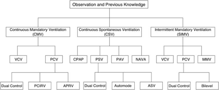
A ventilator mode describes the pattern of breath delivery from the ventilator. With continuous mandatory ventilation (CMV), also called assist/control ventilation (ACV), every breath is a mandatory breath type. With continuous spontaneous ventilation, every breath is a spontaneous breath type. With synchronized intermittent mandatory ventilation (SIMV), the ventilator delivers a mix of mandatory and spontaneous breaths. With CMV or SIMV, a minimum backup rate is set on the ventilator, but the patient can trigger at a more rapid rate. With continuous spontaneous ventilation, there is no backup rate other than the alarm parameter set on the ventilator. The taxonomy of ventilator modes is shown in Figure 130.2.
Continuous Mandatory Ventilation (CMV)
The main feature of CMV (or assist/control ventilation—ACV) is that it supplies full support of the patient's respiratory muscles, provided that the level of support is set appropriately. Disadvantages of CMV are the possibilities of hyperventilation and/or dyssynchrony. The concern of hyperventilation relates to the fact that the patient will always receive the full volume-controlled or pressure-controlled breath, even when triggering at a high frequency. However, this is uncommon because the minute ventilation is controlled by the patient's PaCO2, which will decrease with hyperventilation, thus blunting the drive to breathe. Hyperventilation during CMV may be no more prevalent than with other modes (8). Dyssynchrony can occur particularly when the level of support is insufficient (8).
|
|
|
Figure 130.2. The taxonomy of ventilator modes. APRV, airway pressure release ventilation; ASV, adaptive support ventilation; CPAP, continuous positive airway pressure; MMV, mandatory minute ventilation; NAVA, neurally adjusted ventilatory assist; PAV, proportional assist ventilation; PCIRV, pressure-controlled inverse ratio ventilation; PCV, pressure-controlled ventilation; PSV, pressure support ventilation; VCV, volume-controlled ventilation. |
Volume-controlled Ventilation (VCV)
With VCV, the ventilator controls the flow and the inspiratory time to deliver the resultant tidal volume. In some cases (e.g., Draeger ventilators), tidal volume, flow, and inspiratory time are each set. In this case, an inspiratory breath hold occurs if the inspiratory time setting is greater than that required to deliver the tidal volume at the flow selected. For example, for a tidal volume of 0.5 L, flow 60 L/minute, and inspiratory time 1 second, a 0.5-second inspiratory breath hold will result. On other ventilators (e.g., Puritan-Bennett 840), an inspiratory hold (pause) is set separately, which prolongs the inspiratory time. For VCV, tidal volume, flow, and inspiratory time are the independent variables. The dependent variable is the inflating pressure applied to the lungs, which is affected by the ventilator settings, the patient's lung mechanics, and the inspiratory effort of the patient, as explained by the equation of motion (see above) (9,10). Hence, during VCV, the pressure applied by the ventilator will increase with a higher tidal volume, higher flow, lower compliance, and higher resistance. Also, the pressure applied by the ventilator will decrease if the patient generates a vigorous inspiratory effort (i.e., a higher PMUS). This explains the deformation of the airway pressure waveform during VCV in patients who are generating vigorous inspiratory efforts and are dyssynchronous with the ventilator (9). Inspiratory flow should be set to meet the demand of patients in respiratory failure (11).
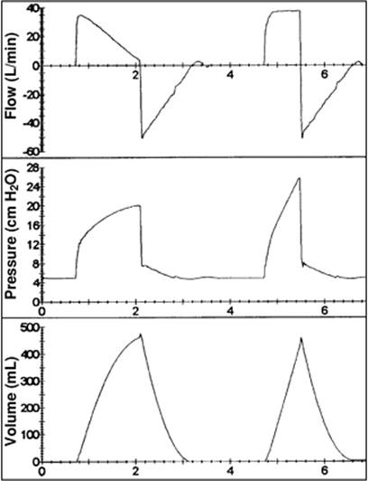
On most ventilators, volume-controlled breaths are delivered by a constant inspiratory flow. This is called a square wave or (more precisely) rectangular flow pattern. In some ventilators, the inspiratory flow can also be set to a descending ramp waveform. With such a flow pattern, the preset peak inspiratory flow is reached early during the breath, after which the flow decreases in a linear fashion, reaching a very low level or zero flow at end-inspiration. This affects the shape of the applied pressure waveform, in which the pressure increases more rapidly at the beginning of inspiration than near the end of inhalation (Fig. 130.3). Moreover, with a descending ramp waveform, the peak inspiratory pressure is lower and approaches the plateau pressure, because the end-inspiratory flow is less than with a constant flow waveform. Note that for the same flow setting on the ventilator, the inspiratory time will be longer for a descending ramp flow waveform than for a constant flow waveform. The longer inspiratory time may result in better oxygenation, but the effect is modest. The longer inspiratory time also increases the risk or air trapping (auto-PEEP) and hemodynamic compromise. For an equivalent inspiratory time, a higher flow setting is required for a descending ramp waveform than for a constant flow waveform.
|
|
|
Figure 130.3. Waveforms for decelerating and constant flow during volume-controlled ventilation. Note the differences in the shape of the pressure waveform and peak inspiratory pressure. |
The main advantage of VCV is the ability to control the tidal volume. This may be important when the PaCO2 must be closely controlled, such as in patients with head trauma or when a low tidal volume is used in patients with acute lung injury/acute respiratory distress syndrome (ALI/ARDS) as part of a lung-protective ventilation strategy (12). Limitations of VCV are related to the fixed tidal volume and flow pattern. This can result in patient–ventilator dyssynchrony in actively breathing patients if efforts are not made to set the inspiratory flow appropriately or to provide adequate sedation (13). With VCV, a high peak inspiratory pressure may occur with changes in lung mechanics. However, this only increases the risk of lung injury if the high peak inspiratory pressure is associated with an increase in plateau pressure. Accordingly, it is important to monitor plateau pressure on a regular basis when VCV is used.
Pressure-controlled Ventilation (PCV)
With PCV, airway pressure and inspiratory time are set on the ventilator. In some cases (e.g., Draeger ventilators), the inspiratory pressure setting is the peak pressure, but more commonly the pressure control setting is the pressure applied above PEEP. For PCV, pressure and inspiratory time are the independent variables. The dependent variables are flow and volume, which are affected by the ventilator settings, the patient's lung mechanics, and the inspiratory effort of the patient as described by the equation of motion (see above) (9,10). Hence, during PCV, the flow and tidal volume will increase with a higher pressure control setting, higher compliance, and lower airways resistance. Also, the flow and tidal volume will increase if the patient generates a vigorous inspiratory effort (i.e., an increase in PMUS). In other words, during PCV, the distending pressure (PVENT + PMUS) and tidal volume increase if the patient makes an active inspiratory effort. Compared to VCV, this may improve patient–ventilator synchrony (14), but with an increased risk of overdistention lung injury. An understanding of the equation of motion as it applies to PCV prevents errors when assessing lung mechanics or risk of overdistention when PCV is used.
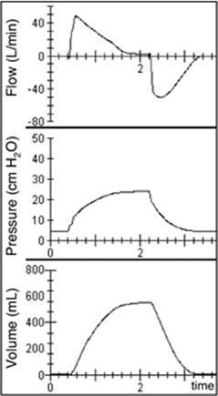
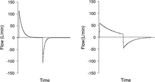
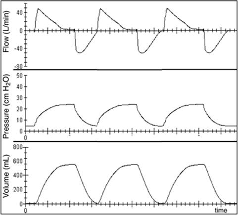
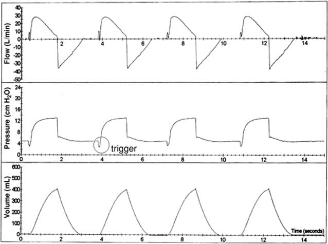
During PCV, the inspiratory flow waveform is a descending ramp (Fig. 130.4). After triggering the breath (by the patient or the ventilator), the ventilator delivers gas to the airway dependent on the capability of the ventilator, respiratory mechanics, and patient effort. The set pressure is applied to the airway until the set inspiratory time is reached. The slope of the descending portion of the inspiratory flow waveform depends on the lung mechanics (Fig. 130.5). The initial flow is high, the flow descent is rapid, and the tidal volume is small when the compliance is low (e.g., ALI/ARDS). On the other hand, the initial flow is low, and the flow descent is slow when the airways resistance is high (e.g., chronic obstructive pulmonary disease [COPD]).
|
|
|
Figure 130.4. Flow, pressure, and volume waveforms during pressure-controlled ventilation. |
|
|
|
Figure 130.5. Effect of changes in respiratory mechanics on gas flow delivery during pressure-controlled ventilation. The left panel shows the effect of a significant decrease in compliance; respiratory mechanics were resistance 10 cm H2O/L/s and compliance 20 mL/cm H2O; the inspiratory time was 1.5 s, and the resulting tidal volume (the area under the flow curve) 400 mL. The right panel shows the effect of a significant increase in airway resistance; resistance was 20 cm H2O/L/s and compliance 50 mL/cm H2O; the inspiratory time was 1.5 s, and the resulting tidal volume 775 mL. |
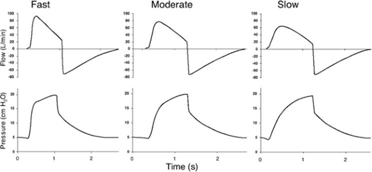
Many current-generation ventilators allow the clinician to adjust the rise time (or pressurization rate), which is the time required for the ventilator to reach the pressure control setting at the onset of inspiration. A fast rise time (one in which the ventilator reaches the target pressure quickly) is associated with a high flow at the onset of inhalation. A slow rise time (one in which the ventilator reaches the target pressure slowly) is associated with a lower flow at the onset of inhalation (Fig. 130.6). Patients with a high respiratory drive should benefit from a fast rise time whereas those with a lower respiratory drive might benefit from a slower rise time (15).
|
|
|
Figure 130.6. Flow and pressure waveforms for three rise times (pressurization rates) at a pressure support of 20 cm H2O. Note the effect of rise time on flow at the initiation of the inspiratory phase. (From Gibbons FK, Hess DR. Mechanical ventilation. In: Bigatello LM, ed. Critical Care Handbook of the Massachusetts General Hospital. 4th ed. Philadelphia, PA: Lippincott Williams & Wilkins; 2006, with permission.) |
A potential advantage of PCV is that it limits the pressure applied to the alveoli and the risk of ventilator-induced lung injury. However, it is important to note that this benefit occurs only if the patient is making no inspiratory effort, because any inspiratory efforts of the patient will increase the transpulmonary distending pressure during PCV. This theoretical advantage of PCV has not been confirmed by appropriately designed clinical trials. The only randomized controlled trial that compared VCV to PCV reported no difference in patient outcomes attributable to the choice of VCV or PCV (16). The variable inspiratory flow pattern may improve patient–ventilator synchrony during active breathing efforts (14), although this has not been tested in the setting of a low lung volume, lung-protective ventilation strategy.
The pressure waveform with PCV produces a higher mean airway (and alveolar) pressure than the pressure waveform associated with constant flow volume ventilation. Theoretically, this may produce better alveolar recruitment for the same end-inspiratory airway pressure. However, the same may be achieved using VCV and a descending ramp flow waveform (17). Compared to constant flow VCV, the low end-inspiratory flow with PCV may improve the distribution of ventilation, which may increase PaO2 and decrease PCO2, but the effect is usually modest.
|
|
|
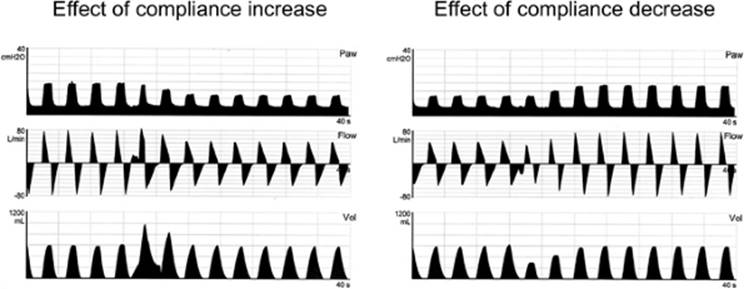
Figure 130.7. Left panel: Effects of an increase in lung compliance on airway pressure (Paw), volume, and flow during dual control with a target tidal volume of 600 mL. Right panel: Effects of a decrease in lung compliance on airway pressure and flow during dual-control ventilation with a target tidal volume of 600 mL. (From Branson RD, Johannigman JA. The role of ventilator graphics when setting dual-control modes. Respir Care. 2005;50:187, with permission.) |
PCV has been recommended in the setting of bronchopleural fistula. Although this makes sense in that alveolar pressure is controlled, on closer examination it can be shown that the leak through a bronchopleural fistula will increase with PCV because the constant alveolar pressure will maintain the pressure gradient for flow and feed the leak through the fistula.
A limitation of PCV is the inability to guarantee a tidal volume and thus the PaCO2. With PCV, changes in respiratory mechanics can result in hypoventilation (or hyperventilation). In particular, PCV can result in hypoventilation in the presence of dynamic hyperinflation and auto-PEEP. For example, if the inspiratory pressure is set at 15 cm H2O, the PEEP is zero, and the patient has an auto-PEEP of 10 cm H2O; the driving pressure will not be 15 cm H2O, but rather 5 cm H2O, resulting in a lower-than-predicted tidal volume. With VCV, this will not occur because the tidal volume will be delivered regardless of the level of auto-PEEP, albeit with a higher inspiratory pressure.
The selection of PCV or VCV is based chiefly on individual preference. If tidal volume, plateau pressure, and transpulmonary distending pressure are carefully monitored, either PCV or VCV can be used safely and effectively.
Dual-controlled Ventilation
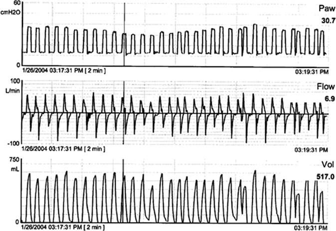
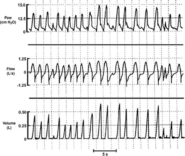
Dual-controlled modes allow the ventilator to control pressure or volume based on a feedback loop. At any given time, the ventilator controls either pressure or volume, but cannot do both at the same time. Pressure-regulated volume control (PRVC) provides PCV, and in addition ensures a minimum tidal volume (18,19,20,21,22,23,24). PRVC (Servo, Viasys), AutoFlow (Draeger), and VC+ (Puritan-Bennett) are trade names that function in a similar manner. Each mode increases or decreases the pressure breath-to-breath by no more than 3 cm H2O per breath in an attempt to deliver the desired tidal volume. The pressure limit fluctuates between PEEP and 5 cm H2O below the upper pressure alarm setting, as illustrated by the example in Figure 130.7. An alarm occurs if the tidal volume and maximum pressure settings are incompatible. The proposed advantage of dual control is the ability of the ventilator to meet patient demand (an advantage of PCV) while maintaining a minute ventilation constant (an advantage of VCV). However, the tidal volume and transpulmonary distending pressure during PRVC can potentially exceed safe limits, as illustrated by the example in Figure 130.8 (21). Moreover, if patient effort increases, the level of support decreases, which could result in dyssynchrony and discomfort (25). Additionally, as the pressure level is reduced, mean airway pressure will fall, potentially resulting in a fall in PaO2. Because this mode depends on the measured tidal volume, any errors in tidal volume measurement will result in decision errors.
Pressure-controlled Inverse Ratio Ventilation (PCIRV)
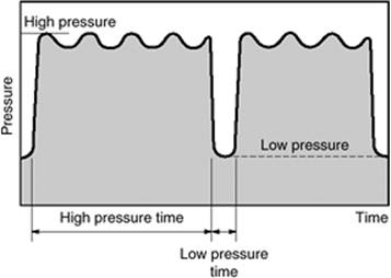
With PCIRV, the inspiratory time is set longer than the expiratory time (Fig. 130.9). The result is a higher mean airway pressure and enhanced lung recruitment, but also a higher potential for air trapping and hemodynamic compromise. Early reports of improved oxygenation with PCIRV generated considerable enthusiasm for this method (26), but subsequent controlled studies reported no, or only marginal, benefit of PCIRV over more conventional approaches (27,28). The oxygenation of some patients may benefit from the use of a longer inspiratory time to increase mean airway pressure. However, the target variable should be the inspiratory time and not an inverse ratio, per se. The likelihood of an improvement in oxygenation using PCIRV is small, and the risk of auto-PEEP and hemodynamic compromise is great. Moreover, the prolonged inspiratory time may not be well tolerated and may require high levels of sedation and, in some cases, paralysis.
|
|
|
Figure 130.8. Airway pressure (Paw), flow, and volume waveforms demonstrating the response of a dual-control algorithm over a 2-minute period with varying patient effort. The tidal volume varies above and below the target (500 mL) by as much as 150 mL. (From Branson RD, Johannigman JA. The role of ventilator graphics when setting dual-control modes. Respir Care. 2005;50:187, with permission.) |
Airway Pressure Release Ventilation (APRV)
Current-generation ventilators use an active exhalation valve; thereby the ventilator controls the inspiratory pressure by allowing the exhalation valve to open if pressure increases and by adding additional flow if the pressure decreases below the pressure control setting. Such a design can also allow spontaneous breathing during the inspiratory phase of the ventilator, which is what happens in APRV (29,30). The ventilator allows spontaneous breathing at two levels of pressure (Fig. 130.10). Because the low pressure is applied for a short period of time, generally all of the spontaneous breathing occurs at the high level. In the absence of spontaneous breathing, APRV is exactly the same as PCIRV.
|
|
|
Figure 130.9. Flow, pressure, and volume waveforms during pressure-controlled inverse ratio ventilation. |
|
|
|
Figure 130.10. Pressure waveform during airway pressure release ventilation (APRV). |
The minute ventilation during APRV results from the amount of spontaneous breathing, the difference between the two pressure levels, and the frequency at which the pressure is released to the lower level. The high pressure level is the main determinant of arterial oxygenation, but the additional spontaneous breaths may further improve gas exchange by preferentially recruiting the dependent lung regions (31,32).
The potential advantage of APRV is to provide lung recruitment at lower airway pressures than with traditional positive pressure ventilation by taking advantage of the spontaneous breathing efforts. This may increase PaO2 while minimizing barotrauma, hemodynamic instability, and the need for sedation. However, this may be an uncomfortable breathing pattern for some patients, resulting in patient–ventilator dyssynchrony, hemodynamic instability, and auto-PEEP. Another concern is the potentially high transpulmonary distending pressure that can occur during spontaneous breathing at the high pressure level. For example, if the high pressure level is set at 25 cm H2O and the patient generates -15 cm H2O during the spontaneous breaths, the inspiratory distending pressure is 40 cm H2O, a level that may increase the risk of ventilator-induced lung injury.
|
|
|
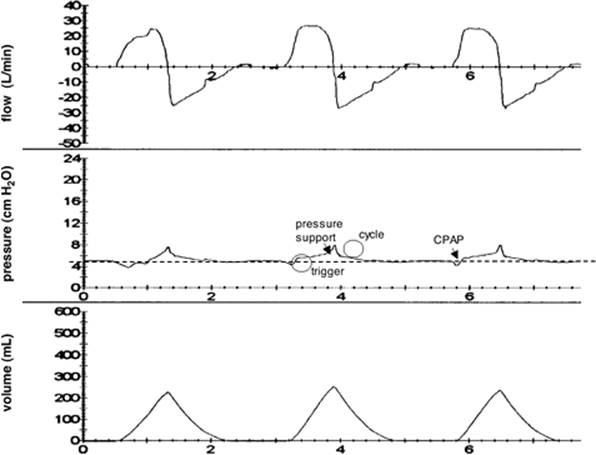
Figure 130.11. Flow, pressure, and volume waveforms during continuous positive airway pressure (CPAP). Note that the airway pressure fluctuates above and below the set CPAP level of 5 cm H2O. There is a pressure decrease below CPAP to trigger the breath, a low level of pressure support is applied during inhalation, and there is a small increase in pressure to cycle the end of inhalation. |
Continuous Spontaneous Ventilation
Continuous Positive Airway Pressure (CPAP)
For the intubated patient, CPAP is usually applied with a ventilator (Fig. 130.11). Modern ventilators provide efficient CPAP by virtue of having very-low-resistance exhalation valves and minimal time delay for triggering and cycling. CPAP is used to treat hypoxemia by maintaining alveolar recruitment to treat acute cardiogenic pulmonary edema by raising intrathoracic pressure, as well as to counterbalance auto-PEEP in patients with obstructive lung disease. Despite an apparent contradiction in terms, CPAP can be set to 0 cm H2O (although in reality the ventilator often applies a small level of inspiratory pressure support), and is commonly used as a spontaneous breathing trial to test extubation readiness.
Pressure Support Ventilation (PSV)
With PSV, the ventilator applies a set inspiratory pressure to support each patient-initiated breath (Fig. 130.12) (33). Tidal volume is determined by the level of inspiratory pressure support, respiratory mechanics, and the patient's inspiratory effort.
The initial part of the breath is delivered in a manner similar to PCV. During inspiration, the flow is delivered at a variable rate. In addition, rise time can be adjusted in a manner similar to that during PCV (34,35). When the set pressure is reached, the flow decreases at a rate determined by lung mechanics and the patient's inspiratory effort.
|
|
|
Figure 130.12. Flow, pressure, and volume waveforms during pressure support ventilation. (From Gibbons FK, Hess DR. Mechanical ventilation. In: Bigatello LM, ed. Critical Care Handbook of the Massachusetts General Hospital. 4th ed. Philadelphia, PA: Lippincott Williams & Wilkins; 2006, with permission.) |
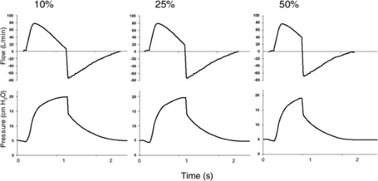
The inspiratory cycle is what distinguishes PCV from PSV. With PSV, inspiration continues until the inspiratory flow falls to a ventilator preset value—commonly 25% of the peak flow or a fixed flow such as 5 L/minute. In newer-generation ventilators, the flow cycle criteria can be adjusted (expiratory sensitivity, Fig. 130.13) (36,37,38,39,40). Setting a high flow cycle (e.g., 50% of the peak rate) will shorten the duration of the breath, whereas a low flow cycle (e.g., 5% of the peak rate) will increase its duration. A higher flow cycle may be desirable for patients with obstructive lung disease, whereas a lower flow cycle is suitable for patients with restrictive lung disease (i.e., acute lung injury). Time and pressure are secondary criteria that can also cycle the breath during PSV, allowing inspiratory termination if the patient actively exhales (pressure cycle) or if there is a leak (time cycle).
PSV is a commonly used mode of ventilation. In many patients, it effectively assists respiratory muscles during invasive mechanical ventilation (41). However, as with any mode, patient–ventilator dyssynchrony can occur if careful attention is not paid to the level of pressure support, the rise time, and the inspiratory cycle. Because there is no backup rate with PSV, it has also been shown that patients receiving this mode of ventilation are more likely to have apnea and sleep-disordered breathing (42).
SmartCare (Draeger) is a closed-loop knowledge-based weaning system for PSV (43). It adapts the level of pressure support to the patient's ventilatory needs, with the goal of keeping the patient within a comfort zone. Comfort is defined primarily as a respiratory rate that can vary in the range of 15 to 30 breaths/minute, a tidal volume above a minimum threshold, and an end-tidal CO2 below a maximum threshold. The level of support is periodically adapted by the system in increments of 2 to 4 cm H2O. The system automatically tries to reduce the pressure level to a minimum value. At this value, a spontaneous breathing trial with a minimal low pressure support level is performed. If successful, a message on the screen recommends removal from the ventilator (i.e., extubation). This mode was shown to reduce the duration of mechanical ventilation as compared with physician-controlled weaning (44).
Dual Control
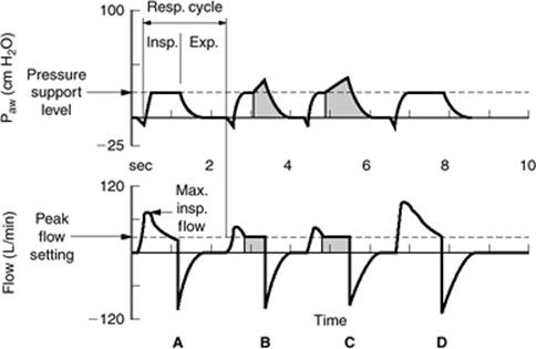
Dual-controlled ventilation can also be applied during a PSV breath. Volume-assured pressure support (VAPS) combines the high initial flow of PSV with the constant flow delivery of a volume-controlled breath (Fig. 130.14) (18,19). After inspiration is triggered, the ventilator reaches the set airway pressure as occurs with PSV. The ventilator's microprocessor determines the volume that has been delivered and compares this to the set tidal volume. If the set tidal volume is not reached, the ventilator prolongs the inspiratory phase until the set tidal volume is delivered. VAPS is designed to reduce the work of breathing (pressure support) while maintaining a minimum tidal volume (volume control). Choosing the appropriate pressure and flow settings is critical to the success of VAPS. If the pressure is set too high or the tidal volume is set too low, all breaths will be PSV breaths. If the flow is set too high, all the breaths will be VCV. If the flow is set too low, the switch from pressure support to volume control will occur late in the breath, and inspiratory time may be unnecessarily prolonged.
|
|
|
Figure 130.13. Examples of flow termination criteria of 10%, 25%, and 50% using a Puritan-Bennett 840 ventilator with pressure support of 15 cm H2O and PEEP 5 cm H2O. (From Gibbons FK, Hess DR. Mechanical ventilation. In: Bigatello LM, ed. Critical Care Handbook of the Massachusetts General Hospital. 4th ed. Philadelphia, PA: Lippincott Williams & Wilkins; 2006, with permission.) |
Volume support (VS) uses PSV in a manner analogous to how PRVC uses PCV (18,19,20,21,22,23). In other words, the ventilator adjusts the inspiratory pressure according to a set minimum tidal volume. If the patient's effort increases (increased tidal volume for the set level of PSV), the ventilator decreases the support of the next breath. If the compliance or patient effort decreases, the ventilator increases the support to maintain the set volume. This combines the attributes of PSV with the guaranteed minimum tidal volume. A concern with this mode is that the ventilator takes away support if the patient's respiratory demand increases and tidal volume exceeds the set tidal volume. This results in increased work of breathing for the patient (25).
|
|
|
Figure 130.14. The possible breath types during volume-assured pressure support ventilation. In breath A, the set tidal volume (VT) and delivered VT are equal. This is a pressure support breath (patient triggered, pressure limited, and flow cycled). Breath B represents a reduction in patient effort. As flow decreases, the ventilator determines that delivered VT will be less than the minimum set volume. At the shaded portion of the waveform, the breath changes from a pressure-limited to a volume-limited (constant flow) breath. Breath C demonstrates a worsening of compliance and the possibility of extending inspiratory time to ensure the minimum VT delivery. Breath D represents a pressure support breath in which the VT is greater than the set VT. (From Branson RD, Johannigman JA. The role of ventilator graphics when setting dual-control modes. Respir Care. 2005;50:187, with permission.) |
AutoMode
AutoMode is a dual-controlled mode available on the Servo 300 and Servo 300A ventilators (18,19). It provides automated weaning from PCV to PSV, and automated escalation of support if patient effort diminishes. The ventilator provides PRVC if the patient is making no breathing efforts. If the patient triggers two consecutive breaths, the ventilator switches to VS. If the patient becomes apneic, the ventilator switches back to PRVC. AutoMode can also switch between PCV and PSV or VCV and VS.
Adaptive Support Ventilation (ASV)
Adaptive support ventilation (ASV) is based on the minimal work-of-breathing concept, which suggests that the patient will breathe at a tidal volume and respiratory frequency that minimizes the elastic and resistive loads while maintaining oxygenation and acid-base balance (45). The ventilator attempts to deliver 100 mL/minute/kg of minute ventilation for an adult and 200 mL/minute/kg for children. This can be adjusted by setting the % minute volume control from 20% to 200%, which allows the clinician to provide full ventilatory support or encourage spontaneous breathing and facilitate weaning.
When first connected to the patient, the ventilator delivers a series of test breaths and measures compliance, resistance, and auto-PEEP. The input of body weight allows the ventilator's algorithm to choose a required minute volume. Lung mechanics are measured on a breath-to-breath basis, and ventilator settings are altered to meet the desired targets. If the patient breathes spontaneously, the ventilator will support breaths. Spontaneous and mandatory breaths can be combined to meet the minute ventilation target. The pressure limit of both the mandatory and spontaneous breaths is adjusted continuously. This means that ASV is continuously using dual-control breath-to-breath of mandatory and spontaneous breaths.
The ventilator adjusts the I:E ratio and inspiratory time of mandatory breaths by calculation of the expiratory time constant (compliance × resistance) and maintains sufficient expiratory time to prevent auto-PEEP. If the patient is not triggering, the ventilator determines the respiratory frequency, tidal volume, and pressure limit required to deliver the tidal volume, the inspiratory time, and the I:E ratio. If the patient is triggering, the number of mandatory breaths decreases, and the ventilator chooses a pressure support that maintains a tidal volume sufficient to ensure alveolar ventilation based on a dead space calculation of 2.2 mL/kg. ASV can provide pressure-limited, time-cycled ventilation, add dual control of those breaths on a breath-to-breath basis, allow for mandatory breaths and spontaneous breaths (dual-control SIMV + PSV), and eventually switch to pressure support with dual control breath-to-breath (variable pressure with PSV). During mandatory breath delivery, the ventilator sets the inspiratory time and I:E ratio.
Tube Compensation (TC)
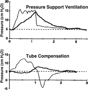
TC is designed to overcome the flow-resistive work of breathing imposed by the endotracheal or tracheostomy tube (46,47). TC uses the known resistive coefficients of the artificial airway (tracheostomy or endotracheal tube) and measurement of instantaneous flow to apply a pressure proportional to resistance throughout the total respiratory cycle. With TC, the ventilator targets the tracheal pressure, rather than proximal airway pressure, increasing the proximal airway pressure necessary to overcome the flow-resistive properties of the artificial airway (Fig. 130.15). The clinician can set the fraction of tube resistance for which compensation is desired (e.g., 50% compensation rather than full compensation). Because in vivo tracheal tube resistance tends to be greater than in vitro resistance, incomplete compensation for endotracheal tube resistance may occur. Additionally, kinks or bends in the tube as it traverses the upper airway and accumulation of secretions in the inner lumen will change the tube's resistive coefficient and result in incomplete compensation. Available evidence suggests that TC can effectively compensate for resistance through the artificial airway but has not shown improved outcomes with this mode (48,49). On some ventilators, TC can be used with any mode, whereas on others, it can be used only with CPAP.
|
|
|
Figure 130.15. Tube compensation. Pressure waveforms from the trachea (heavy lines) and the proximal airway (light lines) during pressure support ventilation and automatic tube compensation. Note that the tracheal pressure fluctuates very little during automatic tube compensation. (From Fabry B, Haberthur C, Zappe D, et al. Breathing pattern and additional work of breathing in spontaneously breathing patients with different ventilatory demands during inspiratory pressure support and automatic tube compensation. Intensive Care Med. 1997;23:545, with permission.) |
Proportional Assist Ventilation (PAV)
With proportional assist ventilation (PAV) (50,51), the ventilator delivers gas as a positive feedback controller, where respiratory elastance and resistance are the feedback signal gains, defined as K1 (cm H2O/L) and K2 (cm H2O/L/s), respectively. In such a system, the pressure at the airway opening is adjusted according to the equation of motion (see above) (9,10)
P = K1 × V + K2 × [V with dot above]
where P is the pressure applied at the airway, [V with dot above] is the inspiratory flow, and K1 and K2 substitute elastance and resistance, respectively. K1 and K2 are the volume and flow gains of the proportional assist ventilator. The ventilator measures the patient's instantaneous inspiratory flow rate and provides the set support through a rapid positive feedback loop (Fig. 130.16).
A potential advantage of PAV is that it should provide optimal patient–ventilator synchrony. By following and amplifying the patient's inspiratory flow and volume on a breath-by-breath basis, the ventilator provides support in proportion to patient demand. This differs from PSV, in which the level of support is constant regardless of demand, and VCV, in which the level of support decreases when demand increases. It is important to note that, like other continuous spontaneous breathing modes, PAV requires the presence of an intact ventilatory drive. In addition, if K1 and K2 are ≥100% of elastance and resistance, “runaway” occurs where the ventilator no longer tracks inspiratory effort. This is similar to the prolonged inspiratory time that can occur during PSV if the pressure is set too high.
|
|
|
Figure 130.16. Airway pressure (Paw), flow, and volume waveforms during proportional assist ventilation. Note that the airway pressure varies with the inspiratory flow and volume demands of the patient. (From Marantz S, Patrick W, Webster K, et al. Response of ventilator-dependent patients to different levels of proportional assist. J Appl Physiol. 1996;80:397, with permission.) |
A concern with PAV is its dependence on measures of resistance and compliance. These can be difficult to measure during spontaneous breathing, and they change frequently over the course of mechanical ventilation. In its initial application, the clinician measured (or estimated) compliance and resistance and set the proportion of inspiratory support that the ventilator would provide, generally as a percentage of elastic and resistive work, respectively. This has been simplified on the commercially available form of PAV (PAV+, Puritan-Bennett 840). Currently, the ventilator applies end-inspiratory and end-expiratory pause maneuvers periodically to determine resistance, compliance, and auto-PEEP. The clinician sets the trigger, the cycle (3 L/minute default), and the % support. The % support is used to partition the work of breathing between the patient and the ventilator. In other words, for 50% support, half of the work of breathing is performed by the patient and the other half is performed by the ventilator.
Neurally Adjusted Ventilatory Assist (NAVA)
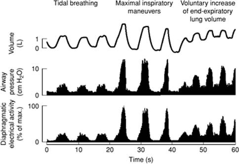
Control of the ventilator through direct measurement of the output of the respiratory center is presently not possible. However, it is possible to transform neural drive into ventilatory output (neuroventilatory coupling) by measuring the electrical activation of the diaphragm. Computer technology and newly developed methods for signal acquisition and processing have made it possible to reliably obtain real-time diaphragmatic electrical activity that is free of artifacts and noise. Diaphragmatic electrical activity can provide a means to give ventilatory assist in proportion to the neural drive, both within a given breath and between breaths (Fig. 130.17). This is called neurally adjusted ventilatory assist (NAVA) (51,52). With NAVA, the magnitude of the support will vary on a moment-by-moment basis according to diaphragmatic electrical activity and the gain factor selected on the ventilator. This allows the patient's respiratory center to be in direct control of the mechanical support provided throughout the course of each breath, provided there is a functioning phrenic nerve and neuromuscular junction, and also that the diaphragm is the primary inspiratory muscle. Through this process, the neural respiratory output is matched to the level of ventilatory assistance. The level of assistance is adjusted in response to changes in neural drive, respiratory system mechanics, inspiratory muscle function, and behavioral influences. Because the trigger is based on diaphragmatic activity rather than pressure or flow measured at the proximal airway, triggering is not adversely affected in patients with flow limitation and auto-PEEP. Although NAVA is clinically attractive, it is not yet commercially available.
Synchronized Intermittent Mandatory Ventilation (SIMV)
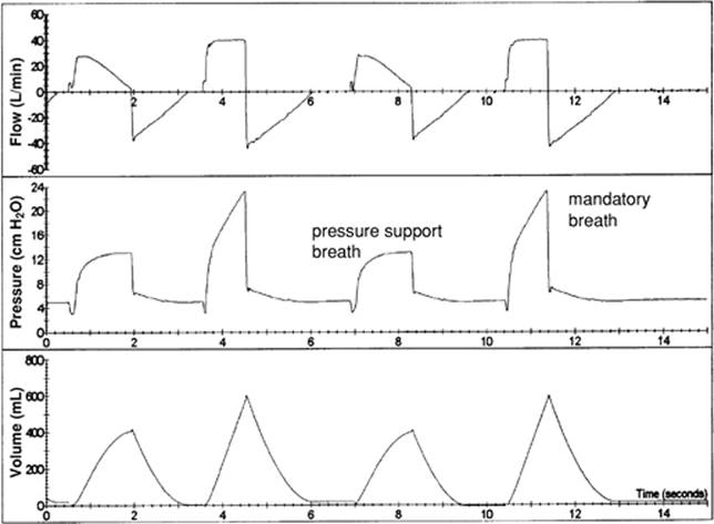
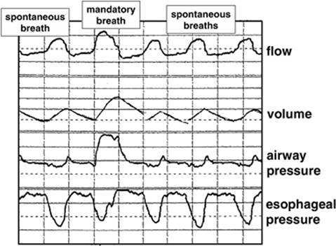
With SIMV, the ventilator provides a mandatory breath rate. If the patient breathes at a more rapid rate, the additional breaths are unsupported. If the patient does not breathe at a rate more rapid than that set on the ventilator, SIMV and CMV are synonymous. The spontaneous breaths may or may not be pressure supported (Fig. 130.18). The mandatory breaths are synchronized to patient effort, and they can be volume controlled, pressure controlled, or dual controlled. It has been traditionally taught that the ventilator does the work for the mandatory breaths during SIMV, and that the patient does the work for the spontaneous breaths. However, this has not been supported by either physiologic studies or outcome studies. Inspiratory effort may be as great during mandatory breaths as spontaneous breaths (Fig. 130.19) (53,54). Moreover, dyssynchrony can occur because different breath types are delivered for the mandatory and spontaneous breaths. This dyssynchrony occurs because the patient's neural controller does not modulate its output based on an anticipated ventilator response.
|
|
|
Figure 130.17. Neurally adjusted ventilatory assist (NAVA). There are continuous proportional adjustments of airway pressure (reflecting ventilatory assist) with changes in diaphragmatic electrical activity (reflecting neural drive) during changes in tidal and end-expiratory lung volumes. (From Sinderby C, Navalesi P, Beck J, et al. Neural control of mechanical ventilation in respiratory failure. Nat Med. 1999;5:1433, with permission.) |
|
|
|
Figure 130.18. Airway pressure, flow, and volume waveforms for synchronized intermittent mandatory ventilation. Note that the mandatory breaths are constant flow, volume-controlled ventilation, and the spontaneous breaths are pressure supported. |
Mandatory Minute Ventilation (MMV)
MMV is intended to guarantee the minute ventilation that the patient receives. If the patient's spontaneous ventilation does not match the target minute ventilation set by the clinician, the ventilator supplies the difference between the patient's minute ventilation and the set minute ventilation. If the patient's spontaneous minute ventilation exceeds what is set, no ventilator support is provided. MMV can be provided by altering the rate or the tidal volume delivered from the ventilator. Some ventilators increase the mandatory breath rate if the minute ventilation falls below the target level, whereas others increase the level of pressure support when the minute ventilation falls below the set level.
|
|
|
Figure 130.19. Airway pressure, flow, volume, and esophageal pressure waveforms during synchronized intermittent mandatory ventilation. Note that the patient's effort during the mandatory breath is nearly the same as that during the spontaneous breaths. (From Hess D, Branson RD. Ventilators and weaning modes. Respir Care Clin N Am. 2000 Sep;6[9]:407, with permission.) |
|
|
|
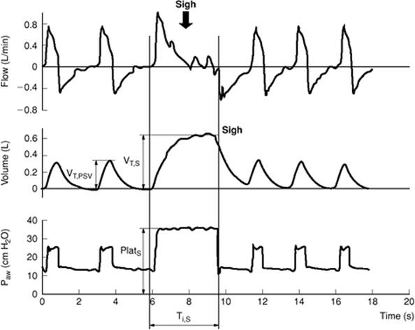
Figure 130.20. Using a sigh breath in conjunction with pressure support ventilation. The patient is ventilated with a Draeger Evita 4 (PCV+ mode). Paw, airway pressure. (From Patronati N, Foti G, Cortinovis B, et al. Sigh improves gas exchange and lung volume in patients with acute respiratory distress syndrome undergoing pressure support ventilation. Anesthesiology. 2002;96:788, with permission.) |
Bilevel and PCV+
This mode is available on the Puritan-Bennett 840 (Bilevel) and the Draeger Evita 4 (PCV+). It is essentially a modification of SIMV that uses PCV for the mandatory breaths and PSV for the spontaneous breaths. This mode can be thought of as PSV with a sigh (55). The mandatory breath rate is set at 1 to 4 breaths/minute, with the pressure during the sigh set at 25 to 30 cm H2O and a sigh duration of 2 to 4 seconds (Fig. 130.20). Because these ventilators have an active exhalation valve, the patient is able to breathe spontaneously when a pressure-controlled mandatory breath is delivered. This mode may be more comfortable than the sighs traditionally incorporated into ventilators because it is a pressure-controlled breath using an active exhalation valve.
Summary
Various ventilator modes are available on modern ventilators. The plethora of settings available for the various modes on modern ventilators can be overwhelming. New modes are often based on technical and engineering capability rather than a clear clinical superiority over previously available modes. There is little evidence that any mode improves patient outcome. Patient outcomes are affected more by how the mode is used than by the mode per se.
Tips and Pearls
1. Goals of invasive mechanical ventilation:
a. Provide adequate oxygenation and ventilation.
b. Maintain alveolar recruitment with adequate PEEP.
c. Avoid overdistention by limiting the plateau pressure.
d. Avoid auto-PEEP.
e. Secure a possibly tenuous airway.
2. The result of any ventilator setting depends not only on what is set on the ventilator, but also on the physiologic characteristics of the patient—namely compliance and resistance, and any active inspiratory effort.
3. For any independent variable set on the ventilator (e.g., pressure), physiologic variables in the patient (compliance and resistance), and effort generated by the patient, there is only one possible result for the dependent variables (e.g., flow and tidal volume).
4. During fully controlled ventilation, bilevel is identical to pressure-controlled ventilation (PCV), and airway pressure release ventilation (APRV) is identical to pressure-controlled inverse ratio ventilation (PCIRV), which is a form of PCV.
5. During pressure ventilation (both pressure-controlled and pressure support), a fast time constant (i.e., low compliance and normal resistance), as is seen in acute lung injury/acute respiratory distress syndrome (ALI/ARDS), may result in a low mean airway pressure and low tidal volume; a slow time constant (i.e., normal or high compliance and high resistance) as is seen in asthma/COPD, may result in a high mean airway pressure, large tidal volumes, and auto-PEEP.
References
1. Chatburn RL. Classification of mechanical ventilators. Respir Care. 1992;37:1009.
2. Chatburn RL. A new system for understanding modes of mechanical ventilation. Respir Care. 2001;46:604.
3. Racca F, Squadrone V, Ranieri VM. Patient–ventilator interaction during the triggering phase. Respir Care Clin N Am. 2005;11:225.
4. Imanaka H, Nishimura M, Takeuchi M, et al. Autotriggering caused by cardiogenic oscillation during flow-triggered mechanical ventilation. Crit Care Med. 2000;28:402.
5. Richard JC, Carlucci A, Breton L, et al. Bench testing of pressure support ventilation with three different generations of ventilators. Intensive Care Med. 2002;28:1049.
6. Goulet R, Hess D, Kacmarek RM. Pressure vs. flow triggering during pressure support ventilation. Chest. 1997;111:1649.
7. Ranieri VM, Grasso S, Fiore T, et al. Auto-positive end-expiratory pressure and dynamic hyperinflation. Clin Chest Med. 1996;17:379.
8. Hudson LD, Hurlow RS, Craig KC, et al. Does intermittent mandatory ventilation correct respiratory alkalosis in patients receiving assisted mechanical ventilation? Am Rev Respir Dis. 1985;130:1071.
9. Nilsestuen JO, Hargett KD. Using ventilator graphics to identify patient–ventilator asynchrony. Respir Care. 2005;50:202.
10. Hess DR, Medoff BD, Fessler MB. Pulmonary mechanics and graphics during positive pressure ventilation. Int Anesthesiol Clin. 1999;37:15.
11. Marini JJ, Rodriguez RM, Lamb V. The inspiratory workload of patient-initiated mechanical ventilation. Am Rev Respir Dis. 1986;134:902.
12. The Acute Respiratory Distress Syndrome Network. Ventilation with lower tidal volumes as compared with traditional tidal volumes for acute lung injury and the acute respiratory distress syndrome. N Engl J Med. 2000;342:1301.
13. Hess DR, Thompson BT. Patient–ventilator dyssynchrony during lung protective ventilation: what's a clinician to do? Crit Care Med. 2006;34:231.
14. MacIntyre NR, McConnell R, Cheng KC, et al. Patient–ventilator flow dyssynchrony: flow-limited versus pressure-limited breaths. Crit Care Med. 1997;25:1671.
15. Uchiyama A, Imanaka H, Taenaka N. Relationship between work of breathing provided by a ventilator and patients' inspiratory drive during pressure support ventilation; effects of inspiratory rise time. Anaesth Intensive Care. 2001;29:349.
16. Esteban A, Alia I, Gordo F, et al. Prospective randomized trial comparing pressure-controlled ventilation and volume-controlled ventilation in ARDS. Chest. 2000;117:1690.
17. Davis K Jr, Branson RD, Campbell RS, et al. Comparison of volume control and pressure control ventilation: is flow waveform the difference? J Trauma. 1996;41:808.
18. Branson RD, Davis K Jr. Dual control modes: combining volume and pressure breaths. Respir Care Clin N Am. 2001;7:397.
19. Branson RD, Campbell RS, Davis K Jr. New modes of ventilatory support. Int Anesthesiol Clin. 1999;37:103.
20. Branson RD, Johannigman JA. What is the evidence base for the newer ventilation modes? Respir Care. 2004;49:742.
21. Branson RD, Johannigman JA. The role of ventilator graphics when setting dual-control modes. Respir Care. 2005;50:187.
22. Branson RD, Johannigman JA, Campbell RS, et al. Closed-loop mechanical ventilation. Respir Care. 2002;47:427.
23. Hess D, Branson RD. Ventilators and weaning modes. Respir Care Clin N Am. 2000;6:407.
24. D'Angio CT, Chess PR, Kovacs SJ, et al. Pressure-regulated volume control ventilation vs. synchronized intermittent mandatory ventilation for very low-birth-weight infants: a randomized controlled trial. Arch Pediatr Adolesc Med. 2005;159:868.
25. Jaber S, Delay JM, Matecki S, et al. Volume-guaranteed pressure-support ventilation facing acute changes in ventilatory demand. Intensive Care Med. 2005;31:1181.
26. Chan K, Abraham E. Effects of inverse ratio ventilation on cardiorespiratory parameters in severe respiratory failure. Chest. 1992;102:1556.
27. Mercat A, Titiriga M, Anguel N, et al. Inverse ratio ventilation (I/E = 2/1) in acute respiratory distress syndrome: a six-hour controlled study. Am J Respir Crit Care Med. 1997;155:1637.
28. Kacmarek RM, Hess D. Pressure-controlled inverse-ratio ventilation: panacea or auto-PEEP? Respir Care. 1990;35:945.
29. Habashi NM. Other approaches to open-lung ventilation: airway pressure release ventilation. Crit Care Med. 2005;33:S228.
30. McCunn M, Habashi NM. Airway pressure release ventilation in the acute respiratory distress syndrome following traumatic injury. Int Anesthesiol Clin. 2002;40(3):89.
31. Putensen C, Mutz NJ, Putensen-Himmer G, et al. Spontaneous breathing during ventilatory support improves ventilation-perfusion distributions in patients with acute respiratory distress syndrome. Am J Respir Crit Care Med. 1999;159:1241.
32. Putensen C, Zech S, Wrigge H, et al. Long-term effects of spontaneous breathing during ventilatory support in patients with acute lung injury. Am J Respir Crit Care Med. 2001;164:43.
33. Hess DR. Ventilator waveforms and the physiology of pressure support ventilation. Respir Care. 2005;50:166.
34. Chiumello D, Pelosi P, Croci M, et al. The effects of pressurization rate on breathing pattern, work of breathing, gas exchange and patient comfort in pressure support ventilation. Eur Respir J. 2001;18(1):107.
35. Chiumello D, Pelosi P, Taccone P, et al. Effect of different inspiratory rise time and cycling off criteria during pressure support ventilation in patients recovering from acute lung injury. Crit Care Med. 2003;31:2604.
36. Du HL, Yamada Y. Expiratory asynchrony. Respir Care Clin N Am. 2005;11:265.
37. Du HL, Amato MB, Yamada Y. Automation of expiratory trigger sensitivity in pressure support ventilation. Respir Care Clin N Am. 2001;7:503.
38. Yamada Y, Du HL. Analysis of the mechanisms of expiratory asynchrony in pressure support ventilation: a mathematical approach. J Appl Physiol. 2000;88:2143.
39. Tassaux D, Gainnier M, Battisti A, et al. Impact of expiratory trigger setting on delayed cycling and inspiratory muscle workload. Am J Respir Crit Care Med. 2005;172:1283.
40. Tokioka H, Tanaka T, Ishizu T, et al. The effect of breath termination criterion on breathing patterns and the work of breathing during pressure support ventilation. Anesth Analg. 2001;92:161.
41. Brochard L, Pluskwa F, Lemaire F. Improved efficacy of spontaneous breathing with inspiratory pressure support. Am Rev Respir Dis. 1987;136:411.
42. Parthasarathy S, Tobin MJ. Effect of ventilator mode on sleep quality in critically ill patients. Am J Respir Crit Care Med. 2002;166:1423.
43. Dojat M, Brochard L. Knowledge-based systems for automatic ventilatory management. Respir Care Clin N Am. 2001;7:379.
44. Lellouche F, Mancebo J, Jolliet P, et al. A multicenter randomized trial of computer-driven protocolized weaning from mechanical ventilation. Am J Respir Crit Care Med. 2006;174:894.
45. Campbell RS, Branson RD, Johannigman JA. Adaptive support ventilation. Respir Care Clin N Am. 2001;7:425.
46. Guttmann J, Haberthur C, Mols G, et al. Automatic tube compensation (ATC). Minerva Anestesiol. 2002;68:369.
47. Guttmann J, Haberthur C, Mols G. Automatic tube compensation. Respir Care Clin N Am. 2001;7:475.
48. Haberthur C, Mols G, Elsasser S, et al. Extubation after breathing trials with automatic tube compensation, T-tube, or pressure support ventilation. Acta Anaesthesiol Scand. 2002;46:973.
49. Cohen JD, Shapiro M, Grozovski E, et al. Extubation outcome following a spontaneous breathing trial with automatic tube compensation versus continuous positive airway pressure. Crit Care Med. 2006;34:682.
50. Grasso S, Ranieri VM. Proportional assist ventilation. Respir Care Clin N Am. 2001;7:465.
51. Navalesi P, Costa R. New modes of mechanical ventilation: proportional assist ventilation, neurally adjusted ventilatory assist, and fractal ventilation. Curr Opin Crit Care. 2003;9:51.
52. Sinderby C, Navalesi P, Beck J, et al. Neural control of mechanical ventilation in respiratory failure. Nat Med. 1999;5:1433.
53. Marini JJ, Smith TC, Lamb VJ. External work output and force generation during synchronized intermittent mechanical ventilation. Effect of machine assistance on breathing effort. Am Rev Respir Dis. 1988;138:1169.
54. Imsand C, Feihl F, Perret C, et al. Regulation of inspiratory neuromuscular output during synchronized intermittent mandatory ventilation. Anesthesiolog. 1994;80:13.
55. Patroniti N, Foti G, Cortinovis B, et al. Sigh improves gas exchange and lung volume in patients with acute respiratory distress syndrome undergoing pressure support ventilation. Anesthesiolog. 2002;96:788.