Keith R. Peters
Scott W. Peterson
Image-guided procedures have increasingly become the standard care due to their minimally invasive nature and comparable or improved outcomes relative to similar procedures without image guidance. Many of these procedures, such as drain placement, can be performed at the bedside allowing unstable patients to remain in the intensive care unit. Procedures that require transport to the radiology department can often be performed with mild sedation or monitored anesthesia care (MAC), without the need for general anesthesia.
Some of the procedures that will be discussed require advanced techniques acquired during fellowship training. For these procedures, the indications, patient preparation, expected outcomes, and potential complications will be discussed. Other procedures, however, may simply represent the use of image guidance to improve outcome and safety of standard clinical procedures, as in the case of ultrasound guided thoracentesis. In discussing these procedures, a more detailed technical description will be provided to assist the clinician performing procedures following appropriate training and supervision. The primary skill to be acquired in the performance of image-guided procedures is the ability to translate the 2-D images that are obtained to the 3-D space in which the procedure is performed. So, as this chapter is read, please consider how some existing procedures could be modified and improved with the use of image guidance and which procedures could be referred to radiology rather than requiring a more open procedure.
Imaging devices that may be used include ultrasound (US), computed tomography (CT), fluoroscopy, and digital subtraction imaging (DSI). All use ionizing radiation, with the exception of ultrasound, and therefore must be performed in areas with appropriate radiation shielding, usually in the radiology department. In some cases, a portable fluoroscopic device in the shape of a “C”—typically described as a portable C-arm—can be brought to the intensive care area provided sufficient radiation shielding is provided the other patients and health care workers, and provided a fluoroscopic-compatible bed/table is available. Federal law requires the use of devices producing ionizing radiation to be supervised by a physician; however, hospital credentialing bodies may have specific training requirements that must also be met. Such is not usually the case with ultrasound. The options for ultrasound devices range from small highly portable handheld units that may be adequate for vascular access and for some drainage procedures, to highly advanced systems with the ability to perform measurements, evaluate vascular flow, and perform 3-D reconstructions. Most ultrasound devices are supplied with multiple probes that vary in frequency of sound wave emitted and device shape, allowing for evaluation of various viewing windows and depths of view.
As each of these procedures is discussed, the more standard imaging methods used at our institution will be described, followed by a brief notation of other possible modalities, for completeness.
Percutaneous Fluid and Abscess Drainage
Percutaneous drainage is an accepted technique for removal of fluid from most locations in the body. The need for exploratory surgery has decreased with improved imaging techniques such as CT, magnetic resonance imaging (MRI), and ultrasound, which can precisely localize a fluid collection. These imaging modalities can then be used to guide the drainage procedure. Combination of percutaneous drainage and antibiotic administration can frequently resolve the infection without the need for surgical intervention. And in cases where subsequent surgery is required, the drains placed under image guidance can be used as a guide to the abscess and potentially decrease the area and extent of surgical dissection.
Evaluation
CT, MRI, and ultrasound can be used in the detection and localization of fluid collections. Ultrasound has the advantage of portability and is very good in the evaluation of fluid in the thorax and in the evaluation of subdiaphragmatic and paracolic collections in the abdomen. However, it is limited by collections of air and is therefore often not able to evaluate mediastinal or central abdominal regions. MRI can localize areas of pathology and fluid collections but is often a less optimal examination due to scan time, exam degradation due to patient motion, and limited availability of interventionally oriented MR scanners and MR-compatible devices for subsequent fluid drainage. Therefore, CT is usually the modality of choice for both localization and drainage.
Image Guidance
As previously stated, most abdominal and central thoracic drainage procedures are performed with CT guidance. Ultrasound can be used for pleural, subpleural, subdiaphragmatic, and paracolic collections. The decision is not only based on location and size but also on operator preference. Imaging must be adequate to define a pathway to the fluid collection. A critical concept is to ensure that the bowel and significant vasculature structures are not entered, and this is best ensured by CT visualization.
Patient Preparation
Review of the patient's medications and coagulation profile is necessary to evaluate potential bleeding risk; we require normalization of prothrombin time (PT) and partial thromboplastin time (PTT). The international normalized ratio (INR) must be less than 1.5, and platelets should be in excess of 75,000 to 100,000 cells/µL. With the potential exception of a thoracentesis or pleural catheter placement, most of these procedures require conscious sedation with an intravenous (IV) narcotic such as fentanyl or hydromorphone, in combination with a short-acting hypnotic sedative such as midazolam. Constant physiologic monitoring is required. Antibiotic coverage should be instituted prior to abscess manipulation due to the concern for precipitation of a septic episode. Previous concerns regarding alterations of culture results have not been sufficiently documented and are outweighed by the potential for life-threatening sepsis. However, if there is low suspicion of infection, such as the case with a large pleural fluid collection, and the patient's white count is within normal limits, antibiotic coverage may not be necessary.
Equipment
Initial access to a fluid collection is usually with an 18-, 20-, or 22-gauge needle. This guide needle can then be used to allow for parallel placement of a drainage catheter with direct stick trocar technique or a wire can be inserted through the guide needle to allow for placement of a drainage catheter using the over-the-wire Seldinger technique.
|
|
|
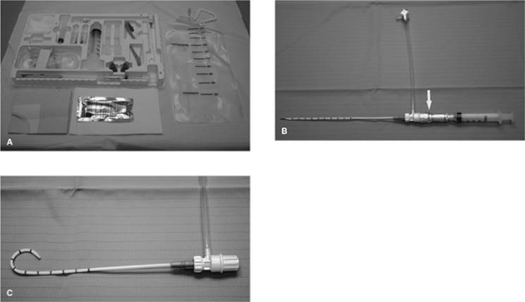
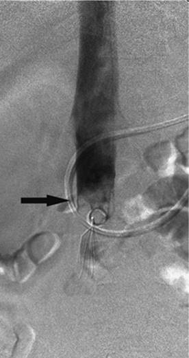
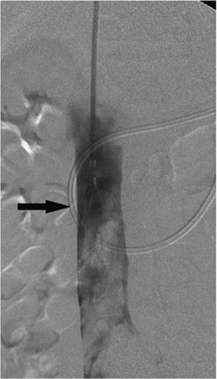
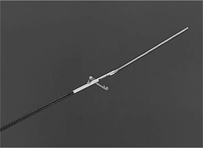
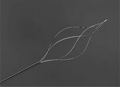
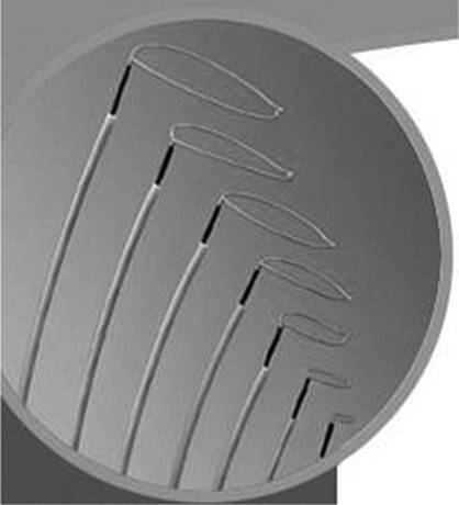
Figure 35.1. Typical drainage tray. A: Layout and contents of the Safe-T-Centesis Catheter Drainage Tray. The kit includes patient prep supplies, a 6 Fr temporary pigtail drainage catheter, and a fluid collection system. B: Safe-T-Centesis device. At the juncture of the syringe and the drainage catheter is an indicator (arrow) that signals the operator when the needle tip enters a free cavity with a color change and an audible click. C: Pigtail catheter unrestrained in the shape it will assume in free cavity. |
For drainage catheters, various catheter shapes and sizes are available. Dual-lumen sump catheters, accordion catheters, and locking loop catheters can be used. The French size of the tube is determined by the type and viscosity of the fluid being drained. An 8 to 12 French catheter can be used to drain a sterile pleural effusion; however, a 16 to 20 French catheter may be required for an abdominal abscess.
Also available for very-short-term use is a Safe-T-Centesis catheter (Cardinal Health, McGraw Park, IL). This is an all-inclusive kit that can be used for draining presumed sterile fluid collections in the chest or abdomen, and in which a drain will not need to be kept in place. This kit also has the advantage of sharps protection in all of the devices (Fig. 35.1A–C).
Drainage Technique
Once localized, an access pathway is identified on CT or ultrasound. The pathway needs to be clear of adjacent solid organs and bowel. A skin entry site is selected and sterilely prepped; in our institution, the prep of choice is 2% chlorhexidine solution in 70% isopropyl alcohol.
Under ultrasound guidance, the needle can be visualized as it is advanced. With CT guidance, small incremental advancements of the needle are made and the position evaluated with repeat imaging. If a Hawkins blunt needle system is used, a sharp inner cannula is used to penetrate the skin and muscle with the blunt cannula used along the remainder of the pathway to displace small vessels. Once at the margin of the collection, the sharp inner cannula is used for final entry. When the fluid collection is entered, a small amount of the material can be aspirated and evaluated by Gram stain to determine if it is infected. This can often be determined by the gross examination of the material. A guidewire is advanced through the needle and coiled in the collection. Fascial dilators are then used to dilate the tract to at least the size of the planned drainage catheter. Finally the catheter is advanced over the wire into the collection, making sure that all side holes are in the collection. This process is monitored by serial CT imaging. When performed under ultrasound guidance for abscess entry, the guidewire and catheter placements are often monitored fluoroscopically if the procedure is performed in radiology. When the catheter is in the fluid collection and imaging has confirmed the position, the contents are completely aspirated. For sterile collections, such as a simple pleural effusion, the catheter can then be removed. For infected or recurrent collections, the drainage catheter is left in place and a drainage collection device attached. The catheter is also secured in place externally by suturing it to the skin with nonabsorbable suture; some institutions use commercially available adhesive devices (Figs. 35.2A–C and 35.3A, B).
An alternative method for catheter placement that can be used for larger and more superficial collections, where there is a larger access window, is the trocar technique. After placement of the guide/reference needle, a selected drainage catheter with its sharp stylet is advanced through a dermatotomy immediately adjacent to and in parallel with the reference needle. There is usually a decrease in resistance to the advancement of the drain when the collection is entered. The sharp stylet is removed, fluid aspirated to confirm position, and the catheter is advanced into the collection off of its internal stiffener and then coiled within the collection. Once drained, the collection is reimaged to ensure complete evacuation. This will also demonstrate the possible presence of loculated areas that must be drained by placement of additional catheters.
|
|
|
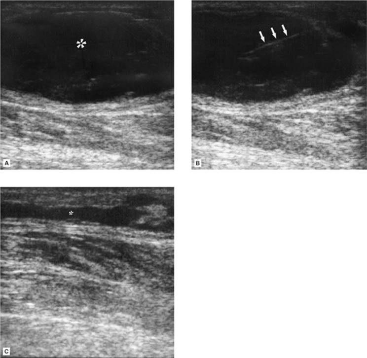
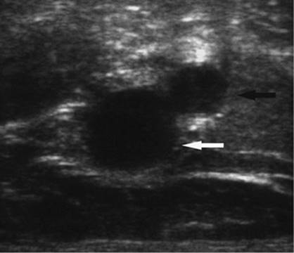
Figure 35.2. A 74-year-old patient on Coumadin developed a focal lower extremity area of swelling, erythema, and progressive pain adjacent to the knee following trauma. A: Ultrasound (US) examination demonstrates a 5.5-mL hypoechoic superficial fluid collection (asterisk). B: Hyperechoic needle (arrows) seen entering the fluid collection. C: Postevacuation US demonstration near complete drainage of the fluid collection (asterisk). The fluid was sterile and consistent with liquefied hematoma. |
|
|
|
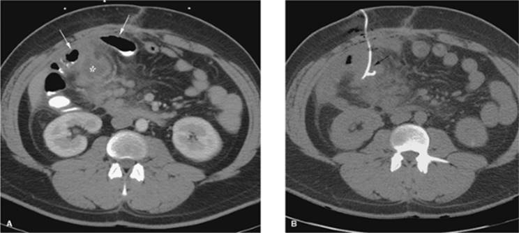
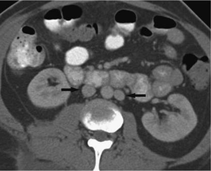
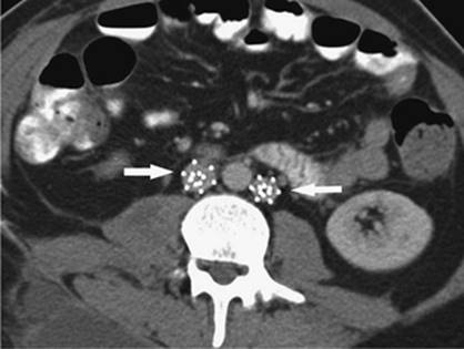
Figure 35.3. Patient with diverticular disease and mesenteric abscess. A: Close proximity of bowel loops (arrows) to the 4-mL fluid collection (asterisk). B: Required CT guidance for drain placement (arrow). |
Postplacement Catheter Care
The catheter is connected to either a gravity drain or a suction device such as a Jackson-Pratt bulb. Output should be recorded by the nursing staff, and the catheter should be irrigated three times a day with sterile saline to maintain patency. The catheter needs to be evaluated daily to confirm patency, evaluate output, evaluate the skin entry site, and to monitor patient clinical status including temperature trend and white count.
End points to determine the time for catheter removal are as follows: decrease in the catheter output to less than 20 mL per day, normalization of temperature and white count, and overall clinical improvement of the patient. When these end points are achieved, the patient is usually reimaged and the tube withdrawn if the collection is no longer present. However, if after 2 to 3 days these end points are not achieved, repeat imaging should also be performed to determine the need for further intervention. Reported success rates for percutaneous abscess drainage are 90% to 100% (1,2,3) with a recurrence rate of 8% to 20%, most commonly related to early catheter removal (4).
Special Considerations
Abscess–Fistula Complex
This is a type of enteric abscess that should be suspected when high fluid output greater than 100 mL per day persists. In this scenario, follow-up evaluation may include injection of iodinated nonionic contrast under fluoroscopic guidance. Results of this study will help determine the need for catheter placement directly into the fistula or surgical intervention. This subgroup often requires 3 to 6 weeks of drainage in association with medical management and nutritional support.
Solid Organ Abscess Drainage
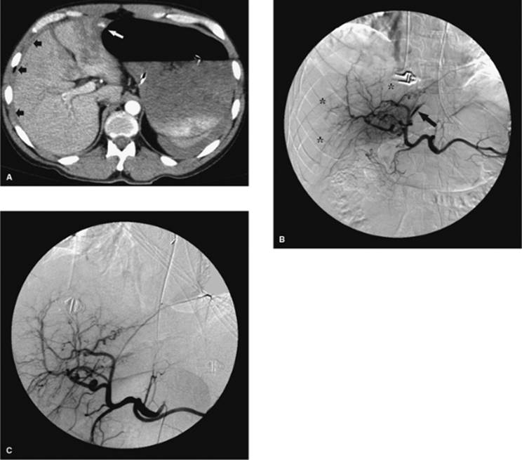
Hepatic, splenic, and renal abscesses can be drained percutaneously, although this sometimes requires an intercostal approach. The lowest possible intercostal level should be used if this approach is necessary to decrease the risk of pneumothorax or the potential spread of infection into the thorax, resulting in empyema. Also, due to the higher risk of bleeding with access into these organs, it is necessary to select the shortest pathway possible through normal tissue, to use a blunt needle system when traversing normal tissue, and to use smaller drainage catheters, usually 8 French. Simple needle aspiration of these collections is preferred over catheter drainage, especially when the collections are small (Fig. 35.4A–C).
Pancreatic Collections
Drainage of pancreatic fluid collections often require CT guidance due to the frequently associated ileus with subsequent overlying bowel loops. Therefore excellent opacification of bowel loops with oral or enteral tube administration of contrast is necessary. Pancreatic abscesses usually contain highly viscous material, which necessitates use of larger-bore catheters (greater than 16 French). Pancreatic pseudocysts usually require only an 8 to 10 French drainage catheter. Additionally, not all pseudocysts require drainage, as most spontaneously resolve. Factors influencing the decision to drain the collection include suspected infection, pain, or obstruction of adjacent bowel or bile duct. Successful pseudocyst drainage can be as high as 90%. However, the results of pancreatic abscess drainage are more variable, with reports of a success rate between 32% and 80%. This wide range is possibly due to difficulty in differentiation of infected pancreatic necrosis, which is difficult to treat, from a focal abscess (5).
Empyema
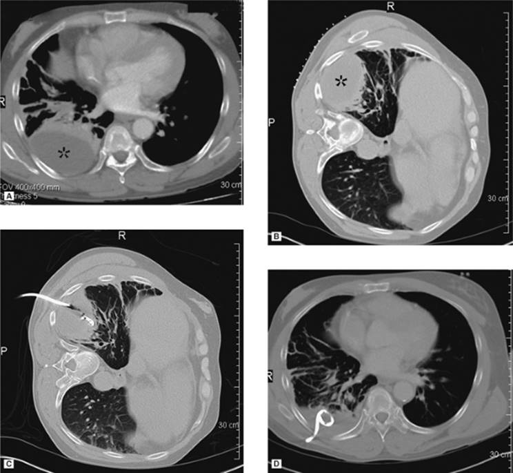
Drainage of an empyema can frequently be performed at the bedside under ultrasound guidance, with the patient's position dependent on his or her ability to assist and the exact location of the collection; a sitting position is often preferred. The collection is localized, entry site marked, site prepped, local anesthesia obtained, and dermatotomy performed followed by deep blunt dissection. A 14 to 20 French catheter is then inserted, often with the trocar technique. The empyema is aspirated and the catheter connected to Pleur-Evac water seal pleural drainage system. The overall success rate for percutaneous drainage of empyema is 77% (6) (Fig. 35.5A–D).
|
|
|
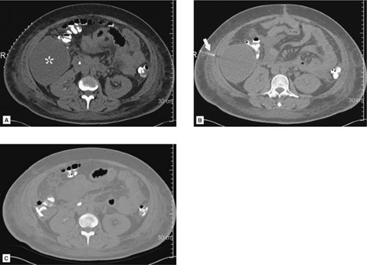
Figure 35.4. CT-guided drainage of infrahepatic abscess. A: CT scan through the fluid collection (asterisk) with localizer grid applied on the skin over the target. B: Following determination of pathway, entry site marking, sterile skin prep and drape, and local anesthesia the access needle is advanced under CT guidance into the fluid collection. Repeat CT is performed to evaluate needle path and depth (arrow). C: Postdrainage obtained at the same level as A shows loop of drainage catheter (short arrow) in markedly decompressed abscess cavity. (Case courtesy of Lauren Alexander, MD, Gainesville, FL.) |
Thick fluid collections may require the use of intrapleural thrombolytic injection such as t-PA, to disrupt fibrin septae. This can be accomplished with an infusion of rt-PA solution containing 2 to 6 mg of rt-PA in 50 to 250 mL of normal saline. This is infused daily for 1 to 3 days. There does not appear to be any significant systemic effect associated with this intralesional infusion of the thrombolytic medication, and there is an approximate 94% clinical improvement rate (7).
Diagnostic and Therapeutic Thoracentesis
Image-guided thoracentesis can easily be performed at the bedside with ultrasound. This is most frequently performed with the patient sitting on the side of the bed facing away from the operator. In some cases, due to severity of the patient's condition, this procedure may need to be performed with the patient supine. This can significantly increase the difficulty of the procedure, especially with smaller collections. This situation can be improved by placing the patient on a cardiopulmonary resuscitation (CPR) backboard to slightly elevate him or her off the bed, and by raising the head of bed as tolerated to drain more of the fluid into a focal dependent position near the diaphragm. Sedation is usually not required as sufficient pain control can be obtained with local anesthesia. Of note, CT may be required in some cases due to the small size and/or location of the fluid.
Diagnostic thoracentesis is often used to differentiate a transudate from an exudate, and in the case of an exudate, to evaluate for malignancy or infection. This diagnostic procedure can be performed with a 20 to 22 gauge needle. Ultrasound is used to localize the collection, and the site of entry is marked. This area is prepped and local anesthesia obtained. The needle is then advanced close to the superior rib margin at the selected intercostal space to avoid the neurovascular bundle that courses along the inferior margin of the rib. Once entered, sufficient pleural fluid is aspirated for laboratory analysis consisting of pH, Gram stain and culture, total protein, lactate dehydrogenase (LDH), glucose, and cytology. At completion of the procedure, the needle is removed and an air-occlusive dressing applied.
Therapeutic thoracentesis is usually requested due to dyspnea or in association with catheter placement for a chemical pleurodesis. A posterolateral approach is used to decrease patient discomfort when lying down and potentially pressing on the tube rather than a direct posterior approach, which is used in standard diagnostic thoracentesis. When a catheter will be necessary only during the short drainage procedure, we use the 6 French catheter that comes in the Safe-T-Centesis kit, with its three-way stopcock and internal valves to decrease the risk of pneumothorax. The fluid is then removed with syringe aspiration or by connection to a vacuum bottle that can be changed when full. Chest pain can occur with rapid fluid removal; however, this usually resolves with temporary cessation of the drainage and with subsequent resumption of the drainage procedure at a slower rate. Coughing often occurs toward the end of the procedure as the pleural surfaces become reapposed. When longer-term access is required, a 10 to 14 French tube is placed by either trocar or Seldinger technique and connected to Pleur-Evac water seal drainage system. The overall incidence of pneumothorax with ultrasound-guided procedures approximates 3% (Fig. 35.6).
|
|
|
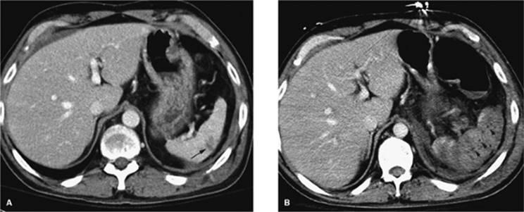
Figure 35.5. A 19-year-old patient with sepsis and cough. A: Axial CT at the level of the midchest demonstrates an 8.5-cm fluid collection in the right posterior hemithorax (asterisk) with compression atelectasis of the adjacent lung. Direct percutaneous access is blocked due to inferior margin of the scapula, overlying ribs, and aerated lung. B: Patient was placed in a left-side-down decubitus position. Change in position provides direct posterior access to the fluid collection. A localizer grid has been placed to mark site of access. C: Access gained with micropuncture needle system and then a 14 Fr drain placed over a wire. Fluid aspirated with syringe and then drain was secured in place and connected to suction bulb. D: Postdrain placement CT. (Case courtesy of Lauren Alexander, MD, Gainesville, FL.) |
If a pneumothorax occurs in association with thoracic intervention, or secondary to underlying lung disease, a chest tube/pleural catheter may be required. The indications for tube placement include size of pneumothorax greater than 25%, pain, shortness of breath, or progressive enlargement on serial radiography. These tubes are easily placed in the second or third intercostal space anteriorly. Our preference is to place an 8 French catheter under fluoroscopic guidance using the Seldinger technique to avoid injury to the adjacent lung. We gain access with a 4 French micropuncture system (Angio Dynamics, Queensbury, NY) followed by insertion of a 0.035 guidewire over which the chest tube is advanced. This is secured in place with nonabsorbable suture and covered with petroleum jelly gauze to decrease the risk of air leak. Most of the pneumothorax is aspirated using a 60-mL syringe with the aid of a three-way stopcock. Then the tube is connected to a Pleur-Evac drainage system as is done with surgically placed chest tubes. The pleural catheter remains in place until there is no significant residual pneumothorax and there is no evidence of air leak when the tube is connected to water seal (Fig. 35.7A–C).
|
|
|
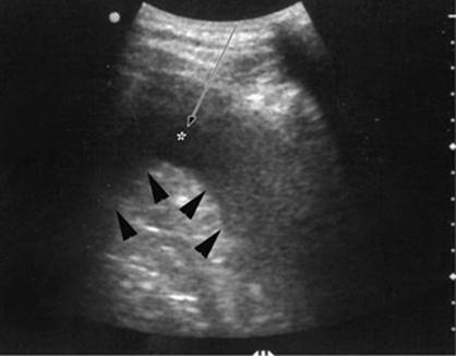
Figure 35.6. Ultrasound image showing typical appearance for thoracentesis guidance. The central target (pleural effusion) is identified by an asterisk, lung margin by arrowheads, and drainage catheter pathway with an arrow. |
Abdominal Paracentesis
Ultrasound or CT guidance can be used to drain diffuse or loculated fluid collections in the abdomen. In most cases, ultrasound is sufficient and can be performed at the bedside. The site of maximal fluid collection is localized without evidence of intervening loops of bowel, and this area is marked and prepped. The procedure can usually be performed with local anesthesia without sedation. The preference at our institution is to use the 6 French Safe-T-Centesis catheter kit. This drainage procedure can be performed for diagnostic and/or therapeutic purposes. When performed as a therapeutic procedure, the catheter and tubing can be connected to either a three-way stopcock and drainage bag or to a 1-L vacuum bottle system. Removal of volumes greater than 5 L can lead to volume redistribution and may require IV albumin infusion (Fig. 35.8A, B).
|
|
|
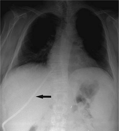
Figure 35.7. A 70-year-old female with progressive pneumothorax following placement of transvenous cardiac pacing device. A: Arrows indicate the partially collapsed left lung following pacing device placement. B: Fluoroscopic image obtained at time of 8 Fr chest tube insertion. The tube was placed slightly lower than the usual apical position to avoid potential damage to the pacing device or wires. C: Following chest tube insertion, the pneumothorax was evacuated with syringe aspiration of the air. Follow-up chest radiograph demonstrates near-completed resolution. The chest tube was connected to Pleur-Evac drainage system. |
|
|
|
Figure 35.8. Abdominal paracentesis. A: Initial position shows a segment of bowel blocking access to the perihepatic fluid. B, segment of bowel; L, liver; asterisk, fluid. B: Slight change in transducer position yields a safe pathway for drainage. |
Suprapubic Drain Placement
The patients in whom placement of a suprapubic cystostomy tube are performed are those with bladder neck obstruction from prostatic hypertrophy or prostate cancer, and with a neurogenic bladder. However, there is an increasing population of ICU patients following pelvic trauma who may also require this procedure.
The procedure is performed under local anesthesia and with conscious sedation. The procedure is usually performed with both ultrasound and fluoroscopic guidance, although in some cases this may be performed at the bedside with ultrasound guidance alone. The bladder must be distended to displace loops of small bowel out of the pelvis. This can be accomplished by the normal filling of the bladder, in the case of outflow obstruction, by filling of the bladder through an indwelling Foley, or by insertion of a 20-gauge needle into the bladder and subsequent filling of the bladder with normal saline. After preparation of the site, if direct access with a needle is used, ultrasound guidance is used to localize the bladder and avoid adjacent loops of small bowel. Once distended, a point 2 to 3 cm above the pubic symphysis is localized in a paramedian location. An 18-gauge needle is advanced under ultrasound guidance, again to avoid any loops of small bowel. The position is confirmed by return of urine, or if saline has been used to distend the bladder, iodinated contrast material can be injected. On confirmation of position, a 0.035-inch stiff guidewire is coiled in the bladder and the tract serially dilated. The degree of dilatation is dependent on type of catheter to be used. For short-term drainage, a soft, 10 to 12 French locking loop catheter can be used. However, for longer-term use, a 16 to 20 French Foley catheter should be used, which can be inserted through a peel-away sheath. Either the locking loop catheter or the peel-away sheath is advanced over the indwelling stiff guidewire under fluoroscopic guidance after sufficient tract dilatation.
Catheter maintenance primarily centers around risk of infection. Some authors recommend use of long-term trimethoprim/sulfamethoxazole. Additionally, the catheter should be exchanged every 2 to 3 months or whenever it becomes clogged with debris. The overall success rate for the procedure approaches 100% (8).
Cholecystostomy
Surgical cholecystostomy was established as a definite technique for decompression of the gallbladder by Sims in 1878 (9). Sims demonstrated that surgical cholecystostomy with insertion of a drainage tube gave rapid relief of symptoms in patients who were otherwise too ill to undergo open cholecystectomy with gallbladder resection (9). Percutaneous access to the gallbladder was first described by Burkhardt and Mueller (10) in 1921, but did not become accepted until 1980, when Shaver et al. (11) demonstrated that percutaneous drainage of the gallbladder was an effective and safe technique in patients with acute cholecystitis who were unfit for surgery (9,10,11). This technique consists of a minimally invasive method of removing gallbladder contents by placing a drainage catheter into the gallbladder lumen using some form of image guidance (9,12,13).
Aside from safe decompression of the gallbladder, percutaneous access to the gallbladder lumen allows additional interventional procedures to be carried out on the gallbladder and biliary tree. Some of these procedures include dissolution of gallstones using methyl-tert-butyl ether (MTBE), gallbladder ablation, percutaneous cholecystolithotomy, and drainage of the biliary tree. However, due to the advent of laparoscopic techniques in the early 1980s, these additional interventional procedures are now rarely performed.
Although surgical or laparoscopic cholecystectomy is the preferred treatment for cholecystitis in the acute setting, cholecystectomy has a substantial mortality rate related to patient issues, including advanced age and coexisting diseases (14). Elective cholecystectomy in a nonacute setting carries a mortality as low as 0.7% to 2%. However, cholecystectomy in the acute patient may have a mortality rate as high as 14% to 19% (14). Percutaneous cholecystostomy can be performed in the acute setting with low mortality rates as a temporizing measure. When the patient has improved and is better able to tolerate an operative intervention, cholecystectomy can be performed electively. In addition, in patients with acalculous cholecystitis, percutaneous cholecystostomy will decompress the gallbladder and may eliminate the need for later cholecystectomy (9).
|
|
|
Figure 35.9. HIDA scan performed on a patient with acute cholecystitis. Note nonvisualization of the gallbladder. |
Acalculous cholecystitis typically occurs in patients admitted for shock, major surgery, and thermal injury, as well as in patients receiving total parenteral nutrition. It is believed to be caused by inflammation and ischemia of the gallbladder, not related to the presence of stones, but rather to intravesicular hemorrhage or inspisated bile causing obstruction, leading to inflammation and infection (14,15). The diagnosis of acalculous cholecystitis can be elusive, as ultrasound and scintigraphy are diagnostically unreliable (9). Percutaneous cholecystostomy has been advocated as a therapeutic trial in these patients provided other sources of sepsis have been excluded (16).
Other indications for percutaneous cholecystostomy include hydrops, empyema of the gallbladder, and complications of cholecystitis including perforation and pericholecystic abscess (17) (Fig. 35.9).
Percutaneous cholecystostomy is usually performed in the angiography suite using ultrasound and fluoroscopy. Computed tomography (CT) scan is another modality that may be of benefit in certain patients (Fig. 35.10). The procedure may also be performed at the patient's bedside using only ultrasound (Fig. 35.11). Although conscious sedation is usually administered, occasionally, if the patient is unable to tolerate conscious sedation, the procedure can be safely performed using only local anesthesia (Figs. 35.12 and 35.13).
|
|
|
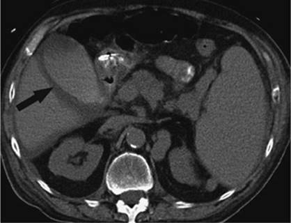
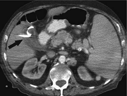
Figure 35.10. CT scan of the same patient as in previous image. Note the thickened gallbladder wall and fluid surrounding the gallbladder. |
|
|
|
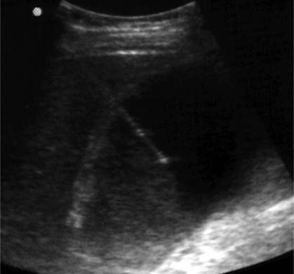
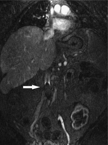
Figure 35.11. Sonographic image obtained during a percutaneous cholecystostomy in the same patient from the previous images. Note the transhepatic approach and tip of the needle within the lumen of the gallbladder. |
The two techniques used are the Seldinger needle and trochar techniques. The Seldinger needle technique involves, after proper preparation, placement of a fine needle, usually 22 gauge, into the lumen of the gallbladder, followed by placement of a 0.018-wire through the needle, and then dilating the site over the wire to accommodate larger wires, if needed, or placement of a drainage catheter. The trochar technique involves placement of a catheter, usually 8 French, which is held on a rigid needle with sharp stylet. This system is advanced as a unit under image guidance into the lumen of the gallbladder. Each needle technique has its own merits and is usually chosen based on operator comfort.
The Seldinger technique allows for a single puncture of the gallbladder, which is then sequentially dilated to accommodate a 0.035 wire. Fascial dilators are then used to accommodate the 8 French drain. It is during the dilation that the guidewire may buckle and access may be lost. If this occurs, the gallbladder may leak into the peritoneum and decompress, making puncture more difficult. The author's experience suggests that if a transhepatic approach is used, this generally does not pose a problem. Alternatively, the trochar technique uses a 22-gauge needle inserted into the gallbladder to be used as a guide to advance the 8 French catheter into the gallbladder. Using this system, a swift stroke of the catheter is require to puncture the gallbladder to prevent the organ from moving away and being displaced. Also, even though bile may be aspirated, the entire catheter may not be in the lumen and when the catheter is advanced, dislodgement may occur. Again, both techniques are widely used and accepted and depend on the operator's comfort level.
|
|
|
Figure 35.12. Contrast injection through the cholecystostomy tube. Note the irregular filling defects consistent with sludge or pus in the gallbladder. |
|
|
|
Figure 35.13. CT scan after successful placement of percutaneous cholecystostomy. Note the catheter in the gallbladder (black arrow). The gallbladder has been decompressed. |
The gallbladder can be approached either via the transhepatic route (Fig. 35.11), attempting to enter through the anatomic bare area, or using a transperitoneal approach. The bare area is formed embryologically when the mesentery that surrounds the gallbladder fuses with the undersurface of the liver. The transhepatic approach tends to minimize bile leak in the presence of ascites. This approach also minimizes gallbladder motion by puncturing near the bare area. This is of significance as it is gallbladder motion that will lead to tube dislodgement. Puncture of the gallbladder by this approach minimizes leakage of bile as the liver will act to tamponade the tract. However, puncture through the bare area has proven difficult in all cases (18). The transperitoneal approach is more direct in some cases and allows better access than the transhepatic approach if percutaneous cholecystolithotomy is planned using a large scope because of the large tract that would have to be formed through the parenchyma of the liver to accommodate the endoscopic device. The main drawback of the transperitoneal approach is when the Seldinger technique is planned, as the gallbladder mobility allows for easy buckling of the catheters due to a lack of parenchymal support, leading to misplaced or dislodged catheters. This problem is largely eliminated if the trochar system is used in combination with the transperitoneal approach.
Cholecystostomy has been well studied and has a 100% technical success rate (11,13,14,16,19) (Fig. 35.13). Procedure-related mortality rates are well documented in the range of 0% to 2%, well below the published rate of complications for surgical cholecystostomy in the acute setting (14,20,21,22). Procedure-related complications include bleeding, vagal response, and biliary peritonitis related to bile leak. Clinical improvement has been shown to occur in 1 to 2 days, and response rates of 87% have been shown at 3 days (9,23). Browning et al. (24) reported that patients with pericholecystic fluid or gallstones were the most likely to have a positive response to the procedure. Ninety-two percent of patients with gallstones showed clinical improvement after percutaneous cholecystostomy. In the ICU, where acute acalculous cholecystitis is most likely to occur, it has been shown that in patients with unexplained sepsis, percutaneous cholecystostomy has shown dramatic clinical improvement, defined as decreased white blood cell count, normalization of body temperature, and reduction in the use of vasopressors, in up to 59% of patients (9,16,19).
Hepatobiliary Drainage
Although the technique of percutaneous cholangiography was first described by Burkhardt and Muller in 1921 (25), it was not until 1966 that percutaneous transhepatic biliary drainage was described by Seldinger (26), using a simple sheathed needle technique. In 1974, Molnar and Stockum (27) described percutaneous biliary drainage using a transhepatic catheter. Subsequent to this description, numerous technical advances were made in the area of guidewires and catheters, which allowed an increased ability to negotiate areas of stricture and stenosis within the biliary tree using a percutaneous approach (25). At present, there is a wide array of devices and instrumentation that allow for increased percutaneous biliary interventions, including management of biliary strictures, biliary leaks, biliary fistulae, stone extraction, biopsies, and radiation therapy.
Whereas percutaneous biliary interventions gained popularity in the 1970s and 1980s, the development of endoscopic retrograde cholangiopancreatography (ERCP) has largely replaced the percutaneous approach for many disease states. However, the technique of choice will mainly depend on the skills available by physicians at the local institution (28). Additionally, there are instances where a percutaneous approach is preferred over an ERCP, mainly instances where ERCP fails, or ERCP is not an option due to prior intestinal surgery that does not allow the endoscope to reach the biliary tree (Figs. 35.14 and 35.15).
Prior to the initiation of the procedure, any coagulopathy should be corrected and prophylactic antibiotics administered. Preprocedure imaging includes either a CT scan, ultrasound, or magnetic resonance imaging (MRI) to look for the location of dilated bile ducts and also to evaluate the anatomy of the liver. The right upper quadrant of the abdomen in the midaxillary line is prepped, using sterile technique, for an intercostal approach. Although the right-sided approach is commonly used, many interventional radiologists prefer to access the biliary tree via a left-sided ductal approach.
After conscious sedation is administered, a 22-gauge needle is advanced into the liver using fluoroscopic guidance. Diluted contrast is injected as the needle is slowly withdrawn; alternatively, the needle can be advanced and contrast injected. This technique works well for the nondilated system. After identifying the biliary system, further contrast is injected slowly to opacify the biliary tree and identify a suitable access site in the bile ducts. Next, with the contrast-filled duct as a target, the system is entered using a 22-gauge needle with fluoroscopic guidance. Thereafter, there are two options. First, an external drain can be placed to decompress the system, with the patient being brought back to the interventional radiology (IR) suite 24 hours later; this reduces the risk of introducing infected bile into the bloodstream. The second option is to attempt internal/external drainage. Although this may save the patient one step in a staged procedure and allow for physiologic drainage of bile, there is a risk of introducing infection as previously described. It is the authors' preference to achieve external drainage first and allow the ducts to drain overnight before attempting any lengthy intervention (Figs. 35.16 and 35.17).
|
|
|
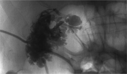
Figure 35.14. Failed endoscopic placement of common bile duct (CBD) stent due to the presence of a large mass (black arrow) within the CBD. (Image courtesy of James Caridi, MD.) |
|
|
|
Figure 35.15. Successful percutaneous drainage using a left-sided biliary duct. Note that the drainage catheter has been advanced past the obstruction and into the small intestine. (Image courtesy of James Caridi, MD.) |
|
|
|
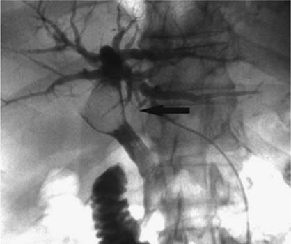
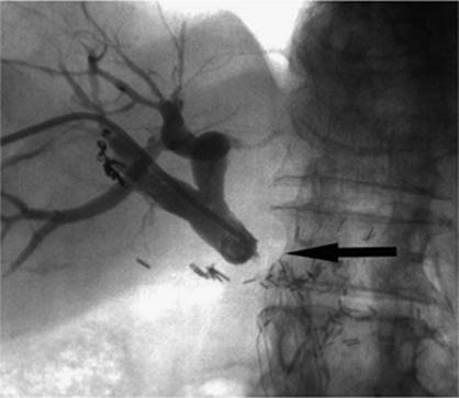
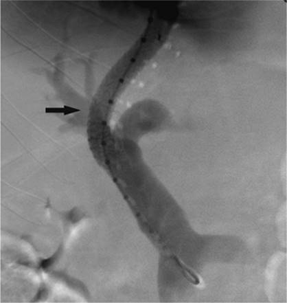
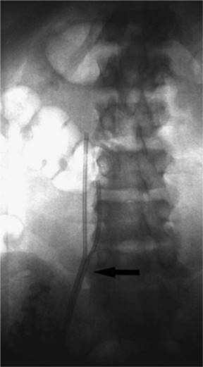
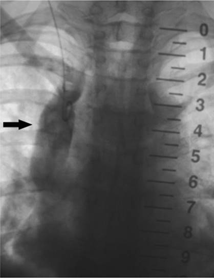
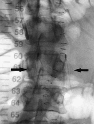
Figure 35.16. Patient presents with biliary obstruction. On hospital day 1, external drainage has been achieved using a right-sided bile duct approach. Cholangiogram shows complete obstruction in the mid common bile duct (CBD) (black arrow). |
The indications for percutaneous biliary drainage include palliation of an unresectable primary or secondary malignancy of the liver causing biliary obstruction, benign strictures including biliary-enteric anastomosis as seen in liver transplant patients, sepsis secondary to biliary obstruction, preoperative decompression, stone removal, bile leak after laparoscopic cholecystectomy, biopsies, permanent internalization of drainage by placement of internal stent, and radiation therapy (29) (Figs. 35.18 and 35.19).
The only true contraindication to percutaneous biliary drainage is a bleeding diathesis. Usually this problem is overcome with the administration of blood products in the form of fresh frozen plasma, platelets, and vitamin K. Relative contraindications include the presence of sepsis, unless it is of biliary origin. The presence of ascites increases the risk of bleeding, and catheter misplacement, as well as making the procedure technically more difficult; hence ascitic fluid should be drained prior to performing the procedure. The presence of multiple intrahepatic obstructions also raises the risk of introducing bacteria to a bile duct that is not drained and that can rapidly become infected.
|
|
|
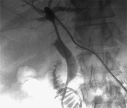
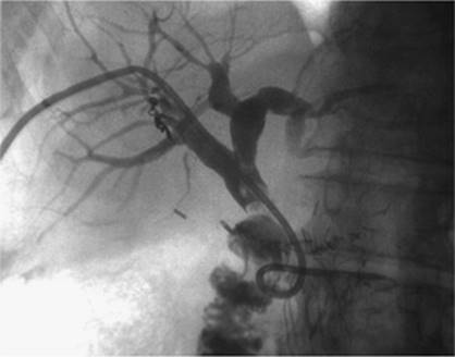
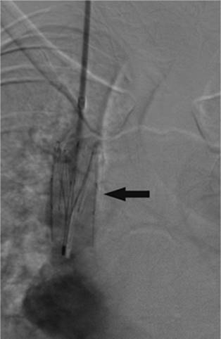
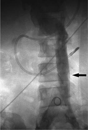
Figure 35.17. On hospital day 2, internal/external drainage has been achieved by gaining access to the small intestine across the area of obstruction. |
|
|
|
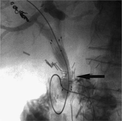
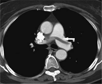
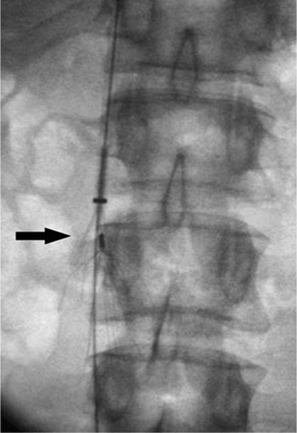
Figure 35.18. This is the same patient as in Figures 35.16 and 35.17. A metallic self-expanding stent has been placed across the area of obstruction in the distal common bile duct. Note the waist in the stent (black arrow) due to the surrounding mass. |
|
|
|
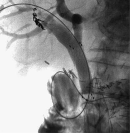
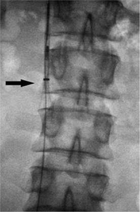
Figure 35.19. Post–stent placement and balloon angioplasty. No residual stenosis is noted, and the stent is fully expanded. |
The catheter should be anchored to the skin. This is usually performed with a suture from the skin to the tube. Approximately 2 cm of slack should be available to prevent tube dislodgement from hepatic motion with respiration. The tube should be flushed with 5 mL of saline every 6 hours for the first 48 hours the tube is in place and then as needed thereafter. The drainage from the tube should be monitored daily to identify any signs of obstruction of the catheter or evidence of bleeding. If brisk bleeding occurs, this may be the result of erosion of the tube through an adjacent hepatic blood vessel that is in continuity with one of the many side holes of the drainage catheter; this usually occurs in the setting of a tube that has migrated out of position with patient motion or inadequate tube anchorage.
The tube site should be cleaned routinely to discourage bacterial colonization. Patients with an external biliary drain in place should receive IV fluids if there is marked choleresis, as this may precipitate hepatorenal failure. If any problem is identified with the tube, IR should be contacted if the problem cannot be resolved immediately on the unit (28).
Burke et al. (30) have reviewed the published success rates of the technique in the literature. Canalization is easier when the intrahepatic ducts are dilated, and success rates approach 95% for the dilated system, whereas it is 70% for the nondilated biliary tree. Internal drainage is achieved in 90% of patients with successful biliary canalization. Stone removal is successful in 90% of cases. Stents placed as palliation for malignant disease are patent 50% of the time at 6 months after placement.
Percutaneous transhepatic biliary drainage carries a significant risk, approximately 10% for all patients (30), and this risk may increase or decrease based on the patient's overall medical condition. Patients presenting with coagulopathy, cholangitis, biliary stones, malignant obstruction, or proximal obstruction will have higher complication rates (30). Complications related to insufficient bile drainage and tube dislodgement is usually relieved with placement of a tube 10 French in size. Sepsis, reported in 2.5% of cases, may be considerable unless prophylactic antibiotics are used prior to the procedure; bleeding is reported with 2.5% of cases as well. Abscess formation or peritonitis is noted in 1.2% of patients; pleura entry is noted in 0.5% of cases. Death is reported in 1.7% of patients.
Although this procedure has several associated complications, it is difficult to compare rates from one institution to another, as patient selection and the presence of other comorbidities may influence complication rates. It is, therefore, important that each institution monitor its own complication rates to ensure quality.
Transjugular Intrahepatic Portosystemic Shunt
Portal hypertension refers to a pathologic increase in pressure in the portal vein. Although it is defined as an increase in portal venous pressure above 12 mm Hg, the standard is to report the portal pressure as a gradient between the portal vein and the inferior vena cava (31). The gradient becomes important because there are several conditions, including pregnancy and ascites, that may elevate the absolute portal pressure or the pressure in the inferior vena cava (IVC).
The liver is the main source of resistance to blood flow in the portal vein (32). Certain disease states, including cirrhosis, disrupt the normal architecture of the liver and lead to formation of fibrosis around the hepatic venules and sinusoids. This fibrosis reduces the diameter of the sinusoids, thus acting to increase resistance. As the pressure in the portal vein increases, one of the ways the body responds is by finding alternate pathways for blood to return to the heart, so called portosystemic collaterals. This is seen as an increase in size of normally small veins within the body, which, as the veins increase to a pathologic size, are called varices. Certain patterns of varices are commonly seen, with the classic distribution in the lower esophagus and stomach. Other common patterns include mesenteric varices and connections between the spleen and kidney. Generally, varices begin to form with a portal pressure greater than 12 mm Hg. Risk of variceal hemorrhage increases as the portal pressure rises to 18 mm Hg.
There have been several methodologies used in treating the complications associated with chronic portal hypertension. Nicolai Eck was the first to achieve surgical portal flow diversion in 1877 (33). In 1945, Whipple et al. (34) and others (35) began using portacaval and conventional splenorenal shunts in clinical practice. Since that time, other shunt procedures have been developed, including end-to-side portacaval shunt, side-to-side portacaval shunt, distal splenorenal shunt, as well as various interposition shunts, all aimed at reducing the pressure in the portal vein and treating variceal hemorrhage (32). Surgery remained the standard until the 1980s when endoscopic techniques were popularized, including direct injection of the bleeding varix with a sclerosing agent. Additional therapies offered through use of an endoscope include banding and ligation of the bleeding varices. Other forms of medical management include administration of vasopressin or vasopressin combined with nitroglycerin using an intravenous route. Vasopressin and its derivatives act by constricting the vascular smooth muscle altering the body's arterial beds including the splanchnic arteries, and thereby reducing the portal pressure by reducing the portal inflow (32). Sclerotherapy has also been performed by direct injection of sclerosing agents into the varices.
The main complication of a successful surgical shunt is the development of encephalopathy, whereas the main drawback to endoscopic and other forms of medical management is that the offending process, portal hypertension, is not addressed, which leads to high rates of rebleeding. These two reasons pressed physicians to develop new treatments.
Transjugular intrahepatic portacaval shunting (TIPS) was first conceived of and performed in dogs in 1969 by Josef Rosch et al. (36). The first human case of percutaneous TIPS was reported in 1988 (37). It is an effective nonsurgical and nonendoscopic means to control variceal bleeding by decompressing the portal venous system (38). A CT scan, ultrasound, or MRI is recommended to evaluate for patency of the portal vein as well as exclude hepatic neoplasm and evaluate for other anatomic considerations. The usual laboratory studies to check for hematocrit and coagulopathy should also be performed. IV antibiotics should be administered prior to the procedure. The technique consists of a percutaneous approach, usually ultrasound-guided canalization of the right internal jugular vein. From this approach, access is gained to the hepatic veins and pressure measurements are made from the portal vein using a wedged technique to the right atrium. A hepatic venogram is performed, followed by angiogram of the portal vein, using carbon dioxide and either a wedged technique or puncture of the hepatic parenchyma through the jugular access. Passage of a long curved needle is then performed from a satisfactory location in the hepatic vein, usually the right hepatic vein, into the identified location in the intrahepatic portion of the portal vein or its branches. Direct pressure measurements are made using the transjugular pathway (Fig. 35.20). If acceptable, balloon angioplasty of the intrahepatic tract between the hepatic vein and the portal vein is then performed. A stent, usually covered, is deployed from the portal vein to the hepatic vein through the tract to keep it patent and prevent hepatic recoil and restenosis (Fig. 35.21). Repeat pressure measurements are performed to confirm satisfactory pressures have been reached. Any additional adjustments that need to be made to the stent can be performed at this time, as well as embolization of varices if indicated.
|
|
|
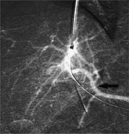
Figure 35.20. Patient with cirrhosis undergoing a transjugular intrahepatic, portacaval shunting (TIPS) procedure. Catheter (white arrow) is positioned from a hepatic venous approach, through the hepatic parenchyma into the portal vein (black arrow). (Image courtesy of Harry K. Meisenbach, MD.) |
When TIPS was first described, it was indicated for uncontrollable esophageal variceal hemorrhage; other indications included gastric or intestinal variceal hemorrhage. The indications have since expanded and now include recurrent variceal hemorrhage despite repeated endoscopic treatment, refractory ascites, hepatic hydrothorax, Budd-Chiari syndrome, and as a bridge to liver transplantation.
TIPS produces profound hemodynamic effects secondary to portosystemic diversion, including decreasing flow to the liver and increasing that to the heart. There are several situations where TIPS is absolutely contraindicated. These include severe or rapidly progressive liver failure, severe encephalopathy, and congestive heart failure. Relative contraindications include biliary obstruction, hepatic malignancy, portal vein thrombosis, and polycystic liver disease; additional considerations include the patient's coagulation status. The most frequent complication is bleeding related to perforation of the hepatic capsule by the needle during attempted canalization of the portal vein. Other considerations include the patient's overall medical condition.
|
|
|
Figure 35.21. Post–transjugular intrahepatic, portacaval shunting (TIPS) angiogram shows a patent TIPS shunt with a covered stent (black arrow). (Image courtesy of Harry K. Meisenbach, MD.) |
The patient's ability to tolerate a TIPS procedure, as well as being a predictor of early mortality, has been calculated in the past using the Child-Pugh classification and the acute physiology and chronic health evaluation II (APACHE II) scores. Today the model for end-stage liver disease (MELD) score has largely replaced other calculations as the best predictor of early mortality. The MELD score is based on the patient's INR, total bilirubin, and creatinine (Cr). The formula is as follows:
MELD score = 10{0.957Ln(Cr) + 0.378Ln(Total bili) + 1.12Ln(INR) + 0.643
where Ln is.
There are a few additional rules when using this formula. For any of the three variables, 1 is the minimum acceptable value. The maximum acceptable value for serum creatinine is 4. The maximum value for the MELD score is 40. It is recognized that a patient's MELD score may change with time and therefore recertification is necessary. How often the score is calculated increases with an increasing MELD score. A MELD score of 18 has generally been shown to be the cutoff for performing a TIPS procedure.
A TIPS procedure is one of the most difficult procedures performed in the IR suite. It involves many steps and as such carries with it a large number of potential complications ranging from bleeding at the puncture site to death. However, many studies have been performed and there are a few likely complications (39,40). It should be noted, too, that there is a learning curve for performing the procedure, which may alter the number and severity of complications.
|
|
|
Figure 35.22. Attempted canalization of the portal vein during a transjugular intrahepatic, portacaval shunting (TIPS) procedure. This CO2 injection identifies canalization of the hepatic artery (black arrow). |
Puncturing the portal vein has proved to be difficult in some cases. Thrusting a large needle blindly through the liver parenchyma can cause a host of complications including bleeding from the liver capsule if the needle perforates the capsule of the liver. Hemobilia can be seen if the needle perforates a bile duct in close proximity to a vascular structure. The needle may leave the capsule of the liver and puncture adjacent organs including the intestine, gallbladder, kidney, and aorta, among others (Figs. 35.22–35.24).
Dilation and stenting of the tract through the liver may also produce numerous complications. If the puncture of the portal vein is extrahepatic, as it has been shown to be in 50% of patients (41), and the tract dilated, fatal hemoperitoneum may result. Stent migration and misplacement have been described. Stents have migrated to the heart, pulmonary arteries, and into the portal vein. Manipulation of wire and catheters within the portal and splenic veins during TIPS may lead to thrombosis of these vessels. Additionally, stents may develop immediate thrombosis after placement, particularly if the angle of the stent is acute or it forms a tight angle with the portal or hepatic vein. There is also a possibility of pulmonary embolism should the thrombus migrate.
Delayed complications occur as well, and a few should be noted. These include contrast-induced nephropathy, hematoma, encephalopathy, stent migration, thrombosis, and elevated right atrial pressures. Often, the procedure may take additional time or a procedural complication may occur, requiring additional contrast that may lead to nephropathy. Rarely a hematoma may occur at the puncture site. Often, TIPS patients are coagulopathic. Although the risk of bleeding is usually recognized at the time of the procedure, as with any angiogram, delayed bleeding may occur. Encephalopathy is not uncommon post-TIPS and ranges from 12% to 34% (38). Treatment consists of lactulose, given orally to help reduce ammonia. If this fails, a flow-reducing stent could be placed to decrease flow through the stent and increase flow back to the liver. Finally, the shunt could be occluded to return the patient to the pre-TIPS state. Although rare, fever may occur postprocedure and may be related to infection or the trauma of the procedure itself. In either case, infection should be ruled out.
|
|
|
Figure 35.23. Attempted canalization of the portal vein during a transjugular intrahepatic, portacaval shunting (TIPS) procedure. The tip of the cannula is in the renal pelvis (black arrow). |
Shunt malfunction can also be considered a complication. Acute thrombosis has already been discussed, but delayed thrombosis is also noted, as well as restenosis and stent shortening. Stenoses within the TIPS may form anywhere along the shunt from the portal vein to the IVC. Stenosis near the end of the stent is usually caused by a stent that is too short and leaves an area of the liver exposed. This leads to narrowing and, ultimately, stent occlusion. Restenosis within the stent itself has been seen, particularly with uncovered stents, and is thought to be related to bile being exposed to the shunt and the development of intimal hyperplasia; this has largely been resolved by the use of covered stents. Finally, the postprocedure right atrial pressures are going to be higher than preprocedure values. If the absolute value is greater than 10 mm Hg, diuresis is recommended.
|
|
|
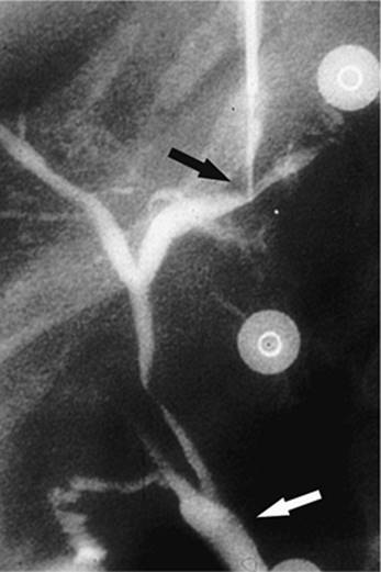
Figure 35.24. Attempted canalization of the portal vein during a transjugular intrahepatic, portacaval shunting (TIPS) procedure. The tip of the cannula is in the left hepatic duct (black arrow). Contrast is noted throughout the biliary system and into the common bile duct (white arrow). |
Follow-up care for TIPS patients is relatively uncomplicated. In addition to evaluating for and treating the delayed complications noted above, one must follow the patient routinely with ultrasound to confirm patency and exclude restenosis or thrombosis of the stent. If this is noted, it is a relatively simple procedure to perform angioplasty of the stenosed segment and return the shunt to its normal function. Ultrasound is usually performed within 1 to 2 weeks after placement of the TIPS; it is repeated at 3 months, 6 months, and then every 6 months and as needed for early identification of any problems with the shunt. It is much easier to maintain a working shunt than to place a new TIPS.
TIPS can be performed with extremely high rates of success, approximating 92% to 99%. Reasons for a failed TIPS procedure include portal vein thrombosis, atrophic hepatic veins, small hard livers, and massive ascites. For patients in whom TIPS was performed for hemorrhage, the procedure was successful in stopping the bleeding acutely in 91.1%, although the risk of rebleeding increases with time up to 20.7% at 2 years. Fatal complications decrease proportionately with the number of procedures that are performed, consistent with a learning curve. Even so, the fatality rate ranges from 0.6% to 4.3%. Published less than 30-day mortality rates range from 4% to 36%. The reason for the variation is multifactorial, based on patient selection and the center performing the procedure. The 5-year mortality rate averages 31.7%, with the most common cause of death being progressive hepatic failure (38).
Central Venous Access
Central venous access and maintenance is one of the most commonly performed procedures in IR (42). The demand for stable, secure, and dependable central venous access has increased dramatically over the past several years as medical therapies have become more complex, and patients present with multiple comorbidities. Additionally, outpatient services have increased sharply as providers have come under increased pressure to reduce hospital costs (43). Today, over 5 million central venous catheters (CVCs) are placed each year in the United States (44,45). CVCs are used in the ICU for infusion of a wide array of medications, blood products, total parenteral nutrition, and can be used for blood draws, hemodialysis, and plasmapheresis as well as many other reasons including contrast administration for diagnostic imaging.
Traditionally, CVCs have been placed by the surgical service, with the radiologist's role limited to confirming satisfactory placement and identifying complications on the postprocedure radiographs. The advent of image-guided procedures allows the IR service to be more involved with vascular access, predominantly in difficult access patients (Fig. 35.25). With time, studies have shown that image-guided vascular access is generally superior to blind insertion, with fewer immediate complications and improved long-term function (1,2,3). Generally, response time for vascular access placement is decreased with IR. Additionally, there are much lower hospital costs in radiology compared to the operating room (46). Certainly, imaging is critical during any complex vascular access procedure including translumbar and revascularization techniques, but the role for image guidance is gaining importance even in routine vascular access procedures as the need for rapid and safe central venous access increases.
|
|
|
Figure 35.25. Grayscale sonographic image of the neck demonstrates clear visualization of the left internal jugular vein (white arrow). The left internal carotid artery is seen as well (black arrow). Additional features used to differentiate the two structures are the increase in vein caliber with Valsalva maneuver compared with the typical arterial pulsation of the carotid artery. |
The field of central venous access has blossomed into a very large industry, with a plethora of devices on the market and virtually every manufacturer of medical equipment supplying their own line of CVCs. It would be difficult to review every manufacturer's devices in this section, but the general categories and catheters will be reviewed.
Peripherally Inserted Central Catheters
In peripherally inserted central catheters (PICC), a peripheral vein in the upper extremity (usually the antecubital, basilica, or cephalic) is cannulated, usually with ultrasound guidance, and a long flexible catheter, essentially a long IV line, is advanced from this puncture site to position its tip in the superior vena cava (SVC) near the right atrium. PICCs come in various sizes and styles, either single- or double-lumen versions, and range from 3 to 7 French. They may have internal valves near the hub, or even on the tip of the catheter, which are important for patients with an allergy to heparin. These valved PICCs are able to be flushed with normal saline, as heparin is not needed to maintain patency. There may also be external clamps that occlude the catheter when it is not in use. The advantage of PICCs include the fact that they are well tolerated by patients, they look and function like a peripheral IV, which allows for ease of use by the nursing staff, and additionally, PICCs carry a lower procedural risk than central lines because they are placed in a peripheral vein, usually avoiding the vital structures in the chest. The single- and double-lumen varieties usually provide sufficient access for most patients. A new “power” PICC configuration has been developed that allows for higher pressures during high-flow contrast injections as seen in CT scans for diagnostic purposes. Many hospitals have entire PICC line teams which are composed of nurses who specialize in placing these at the bedside. If the team is unsuccessful, then the PICC line can usually be placed by an IR clinician or another caregiver specializing in these procedures. Although PICCs are widely used with rapidly increasing acceptance by patients and clinicians alike, there are some associated complications with this type of catheter. One should be aware of the potential complications and long-term ramifications so that the appropriate access can be chosen for each patient.
Venous thrombosis rates, in veins where PICCs are placed, may be as high as 38% (47). It should be noted that Grove and Pevec (48) showed a lower thrombosis rate, up to 9.8% with 6 French catheters, but also demonstrated a positive correlation with catheter size; 3 French catheters had a lower rate of thrombosis than did the 6 French devices. This becomes especially important in planning for dialysis access. If the veins of the upper extremity, commonly used for dialysis fistula, are occluded, fistula creation is more difficult and longevity is reduced. Therefore, in patients with diabetes, chronic renal insufficiency, overt renal failure, or other medical conditions that may lead to renal failure in the future, the preservation of upper extremity and central venous access takes on significant importance (47). Indeed, guideline 7 of the National Kidney Foundation's initiative states that arm veins, which may potentially be used in the creation of a dialysis fistula, should be preserved (49). Any procedure that may increase the risk of venous thrombosis should be avoided.
Bloodstream infections have also been studied with respect to PICCs. Safdar and Maki (50) have noted that PICCs used in the hospital setting have a much higher rate of infection than those used in outpatients. Additionally, they have the same rate of infection as nontunneled central lines and a higher rate of infection than those that are tunneled and cuffed.
Clotting of PICCs has decreased somewhat with the development of valved catheters, although, due to their small size, occluded lumens remain common and require a change of catheter over the wire.
Nontunneled Central Venous Catheters
Nontunneled central venous catheters are generally placed in either the right or left internal jugular veins, or they may be placed in either the right or left subclavian veins, although this location is discouraged due to the potential for venous stenosis. These catheters have either a single-, double-, or triple-lumen configuration. The triple lumen is primarily used for inpatients, especially in the ICU. The triple-lumen catheter is used for relatively short periods of time, up to 14 days, and can accommodate fluids, antibiotics, blood, dialysis, plasmapheresis, and other acute care needs (51). These catheters come in predetermined lengths depending on the site of placement, with left-sided catheters being longer than right-sided catheters, and range in size from 5 to 13 French. They have tapered tips, and some are impregnated with an antibiotic compound to reduce the risk of infection. Although these catheters are usually placed by the clinical team, image guidance is frequently necessary in patients who are obese, coagulopathic, or who have venous abnormalities such as thrombosis or stenosis (51). Complications are still relatively rare with these catheters but are more common and severe than with the PICCs. Again, complications are fewer with image-guided placement than with blind placement (52). Complications include, but are not limited to, hematomata, air embolism, pneumothorax, and nerve injury (53); longer-term complications include mechanical, thrombotic, and infectious causes.
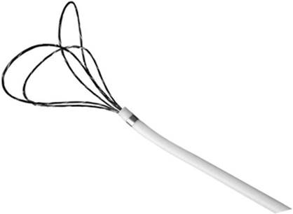
Hematomata are usually treated by applying pressure and correcting any coagulopathy. Air emboli are noted immediately and are usually self-limiting as the air will be dissipated in a few minutes. In extreme cases, additional measures are required, including turning the patient so the left side is down, attempting to aspirate some of the air through the catheter, and administration of oxygen through nasal cannula or mask. Pneumothorax is rare with image guidance, less than 1%, but if this occurs, usually a Heimlich valve chest tube can be placed in the midclavicular line in the second intercostal space. Nerve injury is usually avoided by choosing an appropriate puncture site away from the usual location of nerve pathways. Mechanical complications include fragmentation and migration of the catheter. Fragmentation is more common with subclavian catheters than with internal jugular catheters, due to the pinch-off mechanism between the subclavius muscle, costoclavicular ligament, clavicle, and first rib. Thrombotic complications include thrombus in the catheter, around the catheter, or in the vein near the tip of the catheter. Inability to aspirate blood is usually the first indication of thrombus, and various measures are used to treat this problem. Thrombolytic agents can be placed in the lumen of the catheter in an attempt to lyse the clot. If there is a fibrin sheath around the tip, this can be stripped away using radiologic techniques, such as endovascular balloon disruption of the fibrin sheath or endovascular migration of a snare around the catheter, which is then tightened and pulled down along the catheter to remove the fibrin deposits. If the vein is thrombosed, thrombolysis can be performed if there are no contraindications. Finally, the catheter can be replaced over the wire in certain instances, if one is unable to clear the obstruction from the catheter and other causes have been excluded.
Tunneled Catheters
Tunneled chest wall catheters range in size from 6 to 14 French. They typically have a small Dacron cuff attached circumferentially to the shaft of the catheter, which is placed in a subcutaneous location within the tunnel and allows in-growth of fibrous tissue that secures the catheter in place and reduces the risk of infection. Some cuffs are impregnated with antimicrobial compounds (51). These catheters are generally used long term, on the order of months to years. The typical use for a tunneled catheter includes antibiotics, chemotherapy, fluids, total parenteral nutrition (TPN), blood administration, dialysis, and plasmapheresis. The risks with these catheters are essentially the same as for nontunneled central venous catheters, although fragmentation and thrombosis are seen more commonly in the tunneled devices because they are usually placed for longer periods of time.
Port Catheters
Subcutaneous ports are the final category of central venous catheters to be discussed. Implanted ports are completely contained within the body, with no portion of the device exposed (54). They are either single or double lumen and are constructed of stainless steel, titanium, or plastic and come in various sizes, which helps in choosing a specific port for a patient. These devices are used for chemotherapy, blood administration, fluids, TPN, and antibiotics and require the use of a special noncoring needle. Typically a small subcutaneous pocket is made on the chest wall to accommodate the port. Alternatively, a pocket can be created in the upper extremity and the port placed from this location. However, there is an increased risk of venous thrombosis using ports from the extremity location, and it is generally discouraged (55). Access is obtained into one of the central veins, with the right internal jugular (IJ) vein preferred, as this access carries the lowest immediate and long-term risk to the central veins. The catheter is then advanced through the tunnel and puncture site into the vein. The catheter is cut after measuring the appropriate length from the port to the SVC/atrial junction. The skin overlying the port is closed and, ultimately, heals completely. These devices are used when long-term access is needed, usually on the order of months to years. Advantages of this type of device are its long-term capacity to provide safe, dependable central access, and it allows for a more normal quality of life as there are no exposed portions of the access device; the patient is able to swim and bathe in the usual fashion. The port is easily accessible and is low maintenance. Disadvantages include a more involved initial placement as a subcutaneous pocket is needed. A needle stick is required every time the port is used. Additionally, if a port becomes infected, it requires a more involved procedure to remove it than devices that are not implanted.
Catheter and Site Selection
Choosing the appropriate access site and type of catheter is a complex decision and cannot be standardized, given the complexities of patient care. However there are several basic principles that will help guide one to the most appropriate choice. If the access is to be used for dialysis or plasmapheresis, obviously, high flow rates are needed and larger-sized catheters are needed. A central vein puncture is more appropriate than an extremity vein and, depending on the length of time the catheter is needed, will sway the physician to either a nontunneled or tunneled variety. If the patient is coagulopathic or has other significant comorbidities and access is needed for fluids and routine medications, a PICC could be considered, although caution is recommended if there is a chance the patient may need dialysis in the future. Additionally, a central vein nontunneled device could be considered. If the device is needed infrequently on the order of once per month, an implanted port would be most appropriate.
In general, the safest device that will still meet the needs of the patient should be used. However we realize that supplies and standards vary from hospital to hospital, and that patient and physician preference plays a role as well.
The previously identified and discussed locations and catheters represent the usual and standard approach to central venous access. However, it is not uncommon to have patients with complex histories in whom central venous access is not easily obtained (Figs. 35.26–35.31). For instance, if the subclavian and jugular veins and superior vena cava are occluded and are unable to be revascularized by endovascular techniques, alternate routes must be used. One should be familiar with these alternate pathways for central venous access.
The femoral veins represent a simple approach to the inferior vena cava (Fig. 35.32). These are generally large, relatively superficial veins, the puncture of which is routine using image guidance. Once accessed, a catheter can be placed to the IVC/right atrial junction without difficulty. The main drawback to using this access route is an increased risk of infection. Additionally, it is uncomfortable for patients who are ambulatory.
If the femoral routes are unable to be used, the next appropriate site would be a translumbar access. This involves puncturing the inferior vena cava directly from a posterior approach over the right iliac crest below the level of the renal veins. Once accessed, the tract is dilated to accommodate the catheter, which is directed into the superior portion of the inferior vena cava. This procedure definitely requires fluoroscopic guidance and carries increased risk of procedure-related complications.
One additional site that should be mentioned is the transhepatic approach. When the IVC is occluded and all other sites have been exhausted, vascular access can be achieved by puncturing the intrahepatic portion of the hepatic vein from a right upper quadrant approach, much as if performing a biliary drainage catheter placement. However, instead of aiming for the bile ducts, the hepatic vein is cannulated and the tract dilated to accommodate the appropriate catheter, which is positioned with its tip in the right atrium (Figs. 35.33 and 35.34).
Finally, direct surgical placement of a catheter into the right atrium has been described but is rarely used as access can generally be placed using revascularization techniques from alternate routes (56).
|
|
|
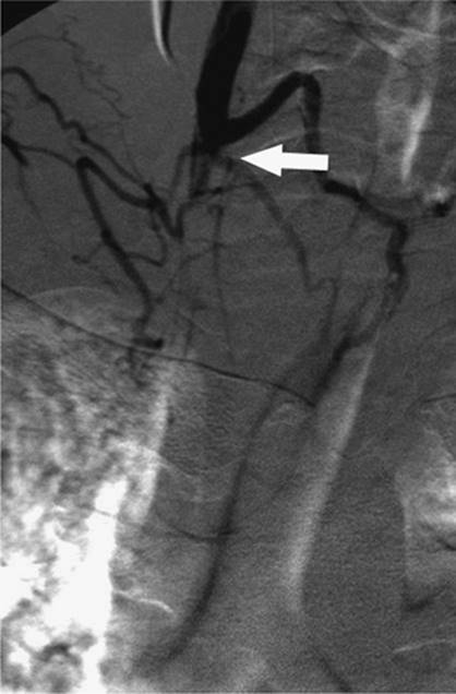
Figure 35.26. Contrast injection of the right internal jugular vein shows complete occlusion at the level of the base of the neck (white arrow). |
Vena Cava Filters
Vena cava filters are small intravascular devices designed to prevent pulmonary embolism by trapping venous emboli. Filters do not prevent formation of new thrombus, nor do they promote lysis of a pre-existing thrombus or embolus. Pulmonary embolism (PE) occurs when thrombus that has formed in peripheral veins breaks free and is carried by the normal venous return to the heart and lungs (57) (Fig. 35.35).
PE is one of the principle causes of hospital mortality, accounting for approximately 200,000 deaths annually in the United States (58). The annual incidence of PE is estimated to be approximately 630,000 (59). The most common source of PE is from deep vein thrombus (DVT) within the lower extremities, although veins in the pelvis and upper extremities can also give rise to PE (57,60). It has been shown that 11% of patients with acute PE die within 1 hour and do not receive therapy. Of those surviving the first hour, the diagnosis is established and treatment initiated in only 29%. The vast majority of patients die because of failure to diagnose. Less than 10% of PE deaths occur in patients in whom treatment is initiated. However, due to advances in diagnostic technology and improvements in treatment, the percentage of patients who die after treatment has been initiated has been decreasing (59).
|
|
|
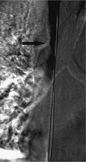
Figure 35.27. Same patient as in Figure 35.26. Access has been obtained across the area of obstruction, and balloon angioplasty is being performed with a 14-mm balloon (black arrow). |
The mainstay of treatment of PE has consisted of anticoagulation, primarily through the use of heparin acutely followed by long-term anticoagulation with warfarin for at least 6 months (57). There are certain situations where patients either fail anticoagulation therapy or in whom anticoagulation therapy is contraindicated. Examples include those patients at high risk for falling, hemorrhagic stroke, trauma, or neoplasm. In these cases, interruption of the vena cava is indicated.
Surgical interruption of the venous system began in the 1930s with the performance of ligation of the common femoral and superficial femoral veins (60). Additional techniques included phlebotomy with thrombectomy. There was a significant incidence of limb edema with vein ligation. Clips that occlude a portion of the inferior vena cava (IVC) were developed throughout the 1960s in an attempt to reduce the amount of limb edema (61). Ligation of the IVC just below the level of the renal veins was described by Oschner in 1970 (62). Although this technique had the same operative mortality as femoral vein ligation, it had a lower incidence of recurrent PE. Still, 10% to 16% of patients had immediate lower extremity edema. New techniques for caval interruption were pursued, and in 1967, the first umbrella filter was developed as a replacement for surgical ligation of the femoral veins and caval clips. Currently, filters represent the standard of care when partial interruption of the vena cava is indicated to prevent PE (60). Most filters have been placed in the inferior vena cava as 75% to 90% of PEs originate in the legs and pelvis (63).
|
|
|
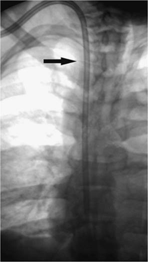
Figure 35.28. Postangioplasty contrast injection demonstrates improved flow in the superior vena cava (black arrow). |
|
|
|
Figure 35.29. Successful placement of a tunneled dialysis catheter (black arrow) in a previously occluded right internal jugular vein. This is the same patient as in Figures 35.26–35.28. |
|
|
|
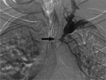
Figure 35.30. Contrast injection of the left internal jugular vein shows complete occlusion of the innominate vein (black arrow). |
|
|
|
Figure 35.31. Successful revascularization of the previously occluded innominate vein with placement of a tunneled dialysis catheter by this left internal jugular venous approach. |
|
|
|
Figure 35.32. Dialysis catheter is noted with its tip (black arrow) in the inferior vena cava, from a right common femoral venous approach. |
It is of significant interest that therapy for upper extremity DVT has been controversial. Some centers elect not to use anticoagulation due to a low incidence of thromboembolism (60). However, more recent studies with larger patient populations have shown an incidence of PE from upper extremity DVT of between 4% and 28%, similar to that for DVT in the lower extremities. In addition, there have been several documented reports of fatal PE due to upper extremity DVT (64). Studies have shown that filters may also be placed safely and effectively in the superior vena cava (64,65) (Figs. 35.36 and 35.37).
The primary indication for filter placement in the vena cava is in a patient with DVT or PE when a contraindication for anticoagulation exists. Contraindications to anticoagulation include hemorrhagic stroke, major trauma, recent neurosurgery, active gastrointestinal (GI) bleeding, intracranial neoplasm, pregnancy, high risk for falling, and poor patient compliance. Additional indications include free-floating thrombus in the vena cava or iliofemoral veins and recurrent PE while undergoing anticoagulation therapy. The indications for filter placement have continued to expand, particularly with the development of retrievable filters (Figs. 35.38–35.41). Placement of a vena cava filter as prophylaxis in patients with high risk for developing PE has also been advocated. These patients include those with marginal pulmonary reserve, those with known DVT about to undergo major surgery, hypercoagulable states like neoplastic processes, and patients with severe trauma who will be in bed for long periods of time (60).
There are only a few relative contraindications to placement of a filter in the vena cava. These include those patients with thrombus between the access site and the deployment site. This has largely been overcome due to the new advances in technology that allow for placement of filters from various locations, including the femoral, jugular, subclavian, and brachial veins. Although MRI was a contraindication in the past, new filters that are MRI compatible have been developed and are now widely used. Infection has long posed a problem in patients needing an IVC filter because the filter could become infected and necessitate surgical removal. However, with the advent of retrievable filters, this has become less of an issue.
|
|
|
Figure 35.33. Magnetic resonance venogram of the inferior vena cava was performed in this patient with difficult venous access. White arrow shows a filter in the inferior vena cava. There is occlusion of the iliac veins. |
The IVC is usually the largest vein in the body. It is responsible for drainage of blood from the legs, pelvis, and abdomen back to the right atrium of the heart. It is formed by the confluence of the common iliac veins at or about the level of L5. It should be noted that at this location, the left common iliac vein crosses under the right common iliac artery and is compressed between the artery and the vertebral body at this location. This often leads to thickening of the vein and leads to thrombosis in the left common iliac vein, the so-called May-Thurner syndrome. Treatment usually consists of stent placement, and the results are best if the stent is placed prior to thrombosis.
|
|
|
Figure 35.34. Same patient as in Figure 35.33. The patient has undergone placement of a dialysis catheter into the hepatic vein (black arrow) with its tip in the inferior vena cava at the level of the right atrium. (Image courtesy of James Caridi, MD.) |
As the IVC runs superiorly, it is joined by the lumbar veins. It is positioned anterior to the right side of the spine and psoas muscle. The right gonadal vein also joins the IVC. The left gonadal vein usually joins the left renal vein. Both renal veins join the IVC at or about L1. Above the right renal vein, the right adrenal veins join the IVC. More superiorly, the three hepatic veins join the IVC just before it empties into the right atrium of the heart at or about T9 (66). The vast majority of IVC's measure between 19 and 20 mm in diameter. There are occasional IVCs with a much greater diameter, the so-called megacavas. This becomes important because many of the filters available at present are indicated for IVCs with a diameter of 2.8 cm or less.
|
|
|
Figure 35.35. CT scan of the pulmonary arteries demonstrates a saddle pulmonary embolism (white arrow) extending into both the right and left pulmonary arteries. |
|
|
|
Figure 35.36. Venogram of the superior vena cava (black arrow) prior to placement of a vena cava filter. |
|
|
|
Figure 35.37. Vena cava filter has been placed in the superior vena cava (black arrow). |
|
|
|
Figure 35.38. Access has been obtained from a jugular venous approach with its wire past the filter, Bard G2, to be retrieved (black arrow). |
Common variant anatomy seen in the IVC includes the double inferior vena cava. This anomaly is seen in 0.2% to 3.0% of patients (67). The embryologic cause is secondary to the persistence of the right and left cardinal veins (63). The left-sided IVC runs superiorly to join the left renal vein, which then crosses anterior to the aorta and joins the IVC. This is important because a filter placed in the right IVC may not fully protect against PE as thrombus may migrate superiorly through the left-sided IVC (Figs. 35.42–35.45). A circumaortic left renal vein is seen in 8.7% of the population. In this scenario, there are two left renal veins. One passes anterior to the aorta to join the IVC in the usual manner while the second runs posterior to the aorta and joins the IVC, frequently at a lower level than the anterior left renal vein. This is important because if a filter is placed between the renal veins, thrombus may travel retrograde in the left posterior renal vein and anterograde through the left anterior renal vein, making the filter ineffective. The retroaortic left renal vein has an incidence of 1.8% to 2.4% and usually enters the IVC at a lower location than the usual left renal vein. This necessitates a lower placement of the IVC filter (63). The left-sided IVC, also called transposition of the IVC, has an incidence of 0.2% to 0.5% (Figs. 35.46–35.48). Interrupted IVC with azygous or hemiazygous continuation occurs in 0.6% of the population. When this is the case, placement of the filter is recommended in the azygous or hemiazygous veins (67). The megacava is seen in approximately 3% of the population and is important as the diameter exceeds the ability of many filters. If an inappropriate filter is chosen, there is a high likelihood of migration centrally. In this case, filters are usually placed in the iliac veins, which will usually accommodate the filters.
|
|
|
Figure 35.39. Recovery cone (black arrow) is positioned over the tip of the vena cava filter. |
The superior vena cava (SVC) is formed by the confluence of the two brachiocephalic veins at the lower margin of the first right costal cartilage. It is generally 7 cm in length and measures 2 cm in diameter. As it courses inferiorly, it enters the superior and posterior portion of the right atrium at the level of the third costal cartilage. It is important to note that the inferior half of the SVC lies within the pericardium. The main tributaries include the azygous vein and other small veins from the mediastinum and pericardium. The double SVC is seen as a result of failure of the left brachiocephalic vein to form and persistence of the left anterior cardinal vein. The left SVC drains into the right atrium via the coronary sinus; this variant is seen in 0.35% of the population. A single left SVC occurs if the right anterior cardinal vein regresses instead of the left. This left-sided SVC also drains into the right atrium via the coronary sinus (68).
|
|
|
Figure 35.40. The tip of the vena cava filter is contained by the recovery cone and is now in the distal portion of the sheath (black arrow). |
|
|
|
Figure 35.41. Vena cava filter has been completely recovered and is now contained within the sheath (black arrow). |
|
|
|
Figure 35.42. Duplicated inferior vena cava (black arrows) as seen on CT scan. |
Imaging of the vena cava is imperative prior to placement of a filter. The cavagram is performed by injecting contrast directly into the vena cava while obtaining a film sequence. The injection should be forceful enough to reflux into the left common iliac vein to exclude a duplicated IVC. The injection should also identify the location of the renal veins and diameter of the IVC. This is the gold standard and is usually performed immediately prior to placement of a filter. However, it is often helpful in planning the access site to have additional studies prior to filter placement. CT scan is perhaps the most widely available modality. Additionally, MRI is very helpful. Ultrasound can be used but is limited by operator dependence and is often limited due to bowel gas.
|
|
|
Figure 35.43. Coronal reconstruction of the CT in the previous image shows the duplicated inferior vena cava (white arrows). |
|
|
|
Figure 35.44. Radiograph of the abdomen demonstrates two separate filters (black arrows) corresponding to filters in each limb of the duplicated inferior vena cava. |
The first filter used was the Mobin-Uddin umbrella filter in 1967. Since the initial success of this filter, numerous other devices have been developed. Currently, there are 11 different filters available for placement, which are approved by the Food and Drug Administration (FDA) and include the following:
|
|
|
Figure 35.45. CT scan of the abdomen demonstrates filters (white arrows) in each limb of the duplicated inferior vena cava. |
|
|
|
Figure 35.46. CT scan of the abdomen demonstrates the inferior vena cava (black arrow) to be positioned on the left side of the aorta. |
1. Stainless steel Greenfield filter (SGF)
2. Titanium Greenfield filter (TGF)
3. Stainless steel Greenfield filter (12F SGF)
4. Vena Tech-LGM filter
5. Vena Tech-LP filter
6. Simon nitinol filter
7. Bird's nest filter (BNF)
8. TrapEase filter
9. Günther Tulip filter
10. Recovery filter
11. OptEase filter
These are made of different materials and all have a slightly different shape and architectural modifications. There are currently three types of filters approved in North America for retrieval. These include the Günther Tulip, Recovery, and the OptEase filters. It should be noted that although some filters are designated as retrievable, this is not possible in all patients. Some limiting factors include trapped clot in the filter, filter tilt, and ingrowth of the filter into the wall of the vena cava.
|
|
|
Figure 35.47. Venogram of the inferior vena cava in the same patient as in Figure 35.46. Note that the inferior vena cava (IVC) is to the left of midline (black arrow). |
|
|
|
Figure 35.48. Plain radiograph of the abdomen demonstrates a filter (black arrow) in the left-sided inferior vena cava (IVC). |
Most filters are placed in the infrarenal IVC. The filter is usually placed as closely as possible to the inferior extent of the renal veins. This reduces the potential dead space between the filter and the renal veins, which is a potential space for clots to form above the filter if the IVC were to occlude secondary to the filter (Figs. 35.49 and 35.50). Placement of the filter above the renal veins is not recommended due to the potential thrombosis of the renal veins. However, it is acceptable to place the filter above the renal veins in certain conditions including renal vein thrombosis, IVC thrombosis extending above the renal veins, recurrent PE in spite of having an infrarenal filter in place, pregnancy, and ovarian vein thrombosis.
Filters have been shown to be safe and effective at preventing PE from an upper extremity venous source. However, there are a few technical considerations. The SVC is shorter than the IVC, and therefore, there is less room to place the filter. Additionally, the filter needs to be inverted, compared to the IVC location. Therefore, it is appropriate to use a filter designed for the IVC from a jugular access and place this in the SVC from a femoral access.
There are many complications reported in the literature, from the initial placement of the filter to long-term complications. Some of the reported complications are unique to each filter based on design and materials used in the construction of the filter. Some of the commonly identified complications include wound hematomas from the access site (2%), sepsis (less than 1%), recurrent PE (5%), filter migration (less than 1%), acute and delayed caval thrombosis (5%), limb edema, retroperitoneal hemorrhage, perforation of the IVC as well as adjacent organs including the aorta, tilting of the filter, and wire prolapse specific to the bird's nest type of filter, failure of the filter to open, fractured filter (1%), and misplacement of the filter in the vena cava (57).
|
|
|
Figure 35.49. Venogram of the inferior vena cava (IVC) shows occlusion of the IVC at the level of the filter. There is some clot (black arrow) extending superior to the filter. |
Foreign Body Retrieval and Manipulation
Foreign bodies have been identified within the vasculature since invasive procedures were first instituted as medical therapy. Foreign bodies pose a particular health risk of infection and hemorrhage. In addition, they can migrate within the body to unsafe locations including the heart and pulmonary vasculature, causing dysrhythmia and shortness of breath. They can migrate to small blood vessels and cause thrombosis. When a foreign body is lost uncontrollably in the vasculature, it puts the patient's life potentially at risk and is intensely anxiety provoking for all caregivers involved.
Surgical removal has been the mainstay for retrieval of foreign bodies until 1964, when the first percutaneous retrieval of a foreign body was described by Thomas et al. (69). At that time, Thomas and Sinclair retrieved a broken segment of steel spring from the right atrium and IVC. Since that time, the number and complexity of percutaneous procedures has increased dramatically. As technology has advanced, producing more therapeutic devices, which are made continually smaller and more technical, the potential for treating numerous diseases with minimal invasion increases. With this tremendous growth of percutaneous procedures come increasing numbers of foreign bodies that are found within the vasculature and body. Percutaneous retrieval of foreign objects has become a mainstay of interventional radiology (70). Egglin et al. (71) have published success rates of 97% for percutaneous foreign body retrieval, and it is now the initial choice of retrieval treatment options (72).
|
|
|
Figure 35.50. Venogram of the inferior vena cava (IVC) shows deployment of a filter (black arrow) above the clot in the IVC. |
The initial foreign bodies identified were related to procedures in which had been lost wires, fragments of diagnostic angiography catheters, portions of balloons, and misplaced or migrating endovascular stents. Increasing numbers and types of procedures have resulted in an increase in foreign bodies, including migrating IVC filters, fragmented catheters—including PICCs—implanted portacaths, dialysis catheters, and CVCs (Figs. 35.51 and 35.52). More recently with the development of embolization techniques using coils, there have been increasing numbers of nontarget embolizations that have prompted additional foreign bodies to be retrieved (73). It is important to note that any device placed within the vascular system is prone to breaking or fragmenting, including fractured pacemaker wires, portions of intra-aortic balloon pumps, biopsy needles, and fragmented deployment catheters, to name but a few (73,74,75). Foreign bodies are not unique to the vascular system. Many examples are discussed in the literature including broken nasogastric tubes, gastrostomy tubes, nephrostomy and ureteral catheters as well as broken drains and others. All of these foreign bodies, while still relatively uncommon, pose a significant threat and usually need to be addressed emergently.
|
|
|
Figure 35.51. A chest radiograph was obtained in this patient with a nonfunctioning portacath in the left subclavian vein. Note the implanted port (white arrow) in the left chest wall. There is disruption of the catheter at the thoracic inlet. The distal fragment is noted in the left pulmonary artery (black arrow). (Image courtesy of Harry K. Meisenbach, MD.) |
Initial retrieval techniques consisted of using homemade snares, which were essentially a diagnostic catheter with an angiographic wire looped through the end to create a loop that was used to encircle the free end of the foreign body and ultimately remove the fragment. Additional devices that were developed were metallic forceps or graspers (70) (Fig. 35.53). It was learned that using fluoroscopic guidance, these biopsy forceps could be guided to the foreign body and used to gain control of the object and pull it out of the body. Other devices include metallic baskets, balloons, and wires with magnetic tips to adhere to the object (73) (Fig. 35.54). Perhaps the greatest single advance was the development of the gooseneck snare originally described by Casteneda in 1991 (76) (Fig. 35.55). This was the first snare device that exits the catheter at a right angle and comes in different sizes, making retrieval of foreign bodies much easier in different-sized vessels. Today, there are many variations of the gooseneck snare; perhaps the most popular is the Ensnare device, which has three loops or snares in one (Fig. 35.56). Additional devices used are deflecting wires, baskets, and suction devices.
|
|
|
Figure 35.52. A second patient with a nonfunctioning portacath in the right chest wall. The implanted port is noted (white arrow). The free fragment of catheter has migrated into the right pulmonary artery (black arrow). (Image courtesy of Harry K. Meisenbach, MD.) |
|
|
|
Figure 35.53. Endovascular forceps allow for grasping foreign bodies. (Image reproduced with permission from Cook Corporation.) |
Unlike other routine angiographic procedures, which are essentially standardized and do not vary significantly from one institution to the next, each foreign body retrieval is unique and necessitates imagination as well as a delicate hand. However, there are some basic principles that should be adhered to when attempting foreign body retrieval. First, does the retrieval procedure pose more risk to the patient than simply leaving the foreign body in its current location? An example of this scenario is an embolized coil to a peripheral branch of the hepatic artery during embolization of a hepatic artery pseudoaneurysm. Although the coil may occlude a small distal branch of the hepatic artery, the dual blood supply to the liver will likely prevent any infarction or ill outcome.
|
|
|
Figure 35.54. Endovascular basket also allows for retrieval of foreign bodies. (Image reproduced with permission from Cook Corporation.) |
|
|
|
Figure 35.55. The gooseneck snare has the snare loop at a 90-degree angle from the wire. This allows for endovascular retrieval of foreign bodies. (Image reproduced with permission from EV3 Corporation.) |
Second, is the foreign body likely to migrate to an unstable position where it poses more of a risk to the patient? An example of this is a fragment of a dialysis catheter that is lodged in the superior vena cava. While at present, the patient may be asymptomatic, the fragment could easily move to the right atrium, right ventricle, or pulmonary vasculature where it could lead to increased risk of pulmonary embolism or dysrhythmia.
|
|
|
Figure 35.56. The Ensnare device has three loops to increase the ability of the snare to trap foreign bodies. (Image reproduced with permission from Angiotech Corporation.) |
Third, it is important to know the exact location of the foreign body. If it has migrated outside the vascular system, then an endovascular approach will be futile and another approach will be necessary. An example of this has been described in the literature with IVC filters that have migrated from their normal infrarenal location to the heart and have a strut extending outside the myocardium (77). Obviously an endovascular approach would not be advised for filter removal in this case.
Finally, can the object be physically removed from the body without causing harm? Some endovascular stents or stent grafts are difficult to remove given their large size. Therefore, in these instances, it is usually in the patient's best interest to move the stent to a location that poses less risk. One example is stents that have migrated from their normal location. These have been successfully repositioned into vessels and locations to minimize any threat of complication.
In general, endovascular retrieval is accepted as a safer, faster, and cheaper method than the surgical alternative. Several examples follow of common retrieval scenarios seen in the ICU.
1. Vascular access catheter fragment in the pulmonary artery. The concept is that most fragments occur at the confluence of the subclavian vein, clavicle, and first rib. When a catheter is present in this location, motion of the arm creates a pinch-type event on the catheter. Over time, the catheter weakens in this location and is susceptible to fragmenting. The approach to the removal of a catheter is to identify the free end of the fragment and attempt snaring, usually from a femoral vein access. This vein is chosen given its size and ability to accommodate larger sheaths and catheters, if needed, for removal. If a free end of the fragment is not readily snared, the catheter can often be moved, using a pigtail catheter, to a more practical location. Alternatively, a wire can be snared around the central portion of the catheter, and the snare and catheter are both pulled out through the same sheath, in effect creating a snare from a regular angiographic guidewire and affecting removal of the foreign body.
2. Migrating, unopened filter in the inferior vena cava. IVC filters are commonly used to prevent fatal pulmonary embolism in patients who have a contraindication to anticoagulation. These devices are made from various metals and come in various shapes and sizes. They are generally sized to the diameter of the IVC. Occasionally, these devices fail to open on release from the deployment sheath. Generally, it is the opening of the filter that anchors it into its location, usually in the infrarenal IVC. When the filter does not open fully on its release, it is prone to cephalad migration and may end up in the heart. With the development of retrievable filters, there are several devices available to grab the tip of the filter and remove it safely, in its entirety.
3. Embolic coils are sometimes challenging to place and may reach a nontarget location if the coil is not sized appropriately to the vessel being embolized. When this happens, the coil should be retrieved if possible, assuming retrieval does not pose additional risk to the patient.
There are a few special scenarios that deserve mention. The following examples are not uncommon to patients in the ICU, and knowledge of their cause and appropriate treatment is important.
1. The “stuck wire” has been described in the literature and is not uncommon (78,79). This usually occurs when the health care provider is placing a central line in the right internal jugular vein. After gaining access to the vein using a needle, a wire is advanced to maintain access while dilating the puncture site to accommodate the central line. After placement of the catheter, the provider meets resistance when pulling on the wire and is unable to withdraw the wire. When a radiograph is obtained, it is noted that the wire is fouled on the struts of an IVC filter. Do not pull the wire as this will result in either dislodging the filter or further tightening the attachment of the wire to the filter. The appropriate next step is to secure the wire on the patient's neck and notify IR. The technique for freeing the wire is the “monorail technique” and has been described in the literature (80). This entails making a small hole in an angiographic catheter approximately 1 cm from its tip and advancing this catheter over the existing wire with the wire exiting the catheter at the newly placed side hole. The stiff end of a wire is then advanced into the catheter from the hub, and the unit is advanced to the level of the filter. This will allow enough torque to free the wire and allow safe removal. This technique should only be performed using direct fluoroscopic visualization.
2. The “knotted catheter” is well known and is usually related to placement of a Swan-Ganz catheter. The balloon tip fails to float freely into the pulmonary artery and as a result, the provider retracts the catheter and then readvances it in an attempt to make it reach the appropriate location. In the process, the catheter becomes entangled on itself and forms a knot. Again, once this is discovered, do not pull the catheter in an attempt to undo the knot as this will only tighten it further making removal more difficult. The appropriate treatment is to notify IR who can then use a series of wires and catheters to undo the free end of the catheter and ultimately remove the knot under direct fluoroscopic guidance.
3. The “migrated PICC” is common to the ICU. Briefly, the patient has had a PICC placed with its tip in the SVC and confirmed by x-ray film. On a subsequent film, the tip of the PICC line is in a suboptimal location in the internal jugular vein. Depending on the medications and fluids going through the PICC, this could pose some risk to the patient. Again, IR is ideally suited for correcting this problem, using fluoroscopic guidance and either a guidewire or other deflecting device, including rapid injection of 5 mL of saline to move the tip into a satisfactory location.
As long as procedures are being performed on patients, we are likely to see various foreign bodies within the vasculature and other organ systems. Increasing technology allows physicians to develop new treatments and increase the number of procedures available. This will certainly lead to an increased variety of foreign bodies identified and with it, place new demands for imaginative techniques to safely remove these objects. Although a loose foreign body inside a patient can be anxiety provoking and may have a potentially hazardous outcome, it is likely that others have encountered the same complication. By understanding the devices used and the techniques available, retrieval should be a relatively mundane experience.
Vascular Mesenteric Pathology
Frequent mesenteric pathologies encountered in the ICU are mesenteric ischemia, gastrointestinal bleeding, and solid organ trauma with hemorrhage. A brief review of the vascular anatomy is essential to the understanding of these pathologies and their treatment. The three major aortic branches supplying the abdominal organs are the celiac artery, the superior mesenteric artery, and the inferior mesenteric artery. The celiac artery arises from the abdominal aorta at approximately the T12/L1 disc space and provides the arterial supply to the liver, spleen, stomach, and pancreas. There are three primary branches—the left gastric artery, which supplies the fundus of the stomach, the common hepatic artery, and the splenic artery. The superior mesenteric artery (SMA) arises from the anterior abdominal aorta approximately 1 to 2 cm distal to the celiac artery and supplies the pancreas, most of the small bowel, and the right colon. The inferior mesenteric artery (IMA) arises from the anterior distal abdominal aorta at the level of L3 and supplies the left colon, the sigmoid colon, and the superior rectum.
Numerous collateral pathways exist between the mesenteric vessels such as the pancreaticoduodenal artery connection between the celiac axis and the SMA, or the middle colic connection between the SMA and IMA. Collateral pathways also exist within these vessel territories such as the communication of the splenic and left gastric branches of the celiac axis through the short gastric arteries. These communications are important in providing collateral circulation in chronic states where atherosclerotic disease is present but may also aid in tissue perfusion when transarterial embolization is required in the treatment of an acute gastrointestinal hemorrhage.
Imaging
Imaging of the mesenteric vessels can be performed with digital subtraction angiography (DSA), CT angiography (CTA), MR angiography, and, to some extent, with ultrasound and nuclear medicine. DSA remains the gold standard in the evaluation of the mesenteric vessels. This study requires performance in the angiography suite, and, depending on the patient's condition, conscious sedation administration or anesthesia may be required. Most of the bowel must be free of significant amounts of residual barium or Gastrografin contrast agents from prior studies. The procedure includes abdominal aortography and selective catheterizations of at least the celiac trunk, SMA, and IMA. However selective catheterizations of additional vessels such as the splenic artery, the left gastric artery, or hepatic artery are often required. Therefore proper renal function or support is critical due to potential total iodinated contrast dose.
CTA can also be used in the initial evaluation of suspected abdominal pathology. This is performed with a baseline noncontrast CT of the abdomen and pelvis followed by rapid IV bolus administration of 100 to 150 mL of iodinated contrast material with associated thin-section imaging followed by postadministration contrast-enhanced CT. Multiplanar reformations and CT angiography can be performed off line of the thin-section CT data to create arterial images. CT has advantages of not only being able to evaluate the proximal vessels but also the ability to evaluate the perfusion of the visceral organs and status of the bowel wall. MR and magnetic resonance angiography (MRA) can provide similar data as with CT; however, the study is often degraded by patient motion or the presence of metallic implants such as IVC filters or surgical clips. The lack of significant nephrotoxicity of the gadolinium contrast agents may allow for a more focused DSA examination in patients with compromised renal function. Ultrasound can be used in the initial evaluation of abdominal pathology but is limited in its ability to evaluate the vasculature. The aorta can be well demonstrated as can the celiac trunk and SMA. However, distal branches of these vessels and the IMA are usually not imaged due to their small caliber (Fig. 35.57A–F).
Nuclear medicine imaging is of importance in evaluation of patients with gastrointestinal bleeding. Evaluation with a 99mtechnetium-tagged red blood cell study can detect bleeding at a rate of 0.1 mL per minute compared with the 0.5 to 1 mL per minute required for DSA.
Mesenteric Ischemia
This process resulting from inadequate blood supply to the intestine is usually seen in elderly patients and results in bowel inflammation and injury. The most common form is acute mesenteric ischemia, a result of emboli or hypotension. The less common chronic form is most often secondary to atherosclerotic disease producing hemodynamically significant stenoses in at least two of the three mesenteric arteries (81). Our discussion will focus on acute mesenteric ischemia, as it is not only a cause of admission to the intensive care unit, but can also be present as a comorbidity in the ICU patient population.
Acute mesenteric ischemia can be a true emergency with mortality exceeding 80% without rapid intervention in most reports. Many cases—approximately 50%—are secondary to an embolic event, usually cardiac or aortic in origin. However, approximately 20% are due to thrombosis of an existing atherosclerotic lesion, 20% due to prolonged hypotension, and 10% due to mesenteric venous thrombosis (82,83).
Findings on plain abdominal film are nonspecific early in the course of ischemia, with air in the bowel wall or in the portal vein seen only as a late finding. CT is an excellent screening examination, especially when combined with CT angiography. However, if intestinal ischemia is suspected, oral contrast should not be administered as this will degrade any subsequent DSA study. CT examination with IV contrast administration will allow visualization of the bowel wall and the arterial and venous structures. DSA remains the gold standard in the imaging evaluation of suspected acute mesenteric ischemia. The most common finding is that of an embolus within the SMA, particularly at its origin. Many of these emboli will fragment and migrate distally in the SMA and result in more significant ischemia as the collateral pathways are occluded. Emboli to other sites may also occur. The primary role of interventional radiology in these cases is diagnostic (84). In those patients without peritoneal signs or evidence of bowel infarction, intra-arterial thrombolysis or suction thrombectomy may be attempted and has been shown to be beneficial in select case reports. However, surgical thrombectomy and resection of infarcted bowel remains the standard of care (85).
|
|
|
Figure 35.57. Rotational views from a magnetic resonance (MR) abdominal aortogram in a patient with right-sided renal hypernephroma. A: Frontal view with full field of view demonstrates normal caliber left renal artery (arrowhead) compared with dilated right renal artery (double arrowheads). The branches of the right renal artery are splayed around a large mass extending from the lower pole of the kidney (asterisk). B: Magnified view of A. Also note the appearance of the normal splenic artery (SA), common hepatic artery (CH), and lumbar arteries (LA). C: Further rotation of B to the lateral projection allows visualization of the celiac trunk (thick arrow) and the superior mesenteric artery (arrow). D–F: Three other patients demonstrating imaging modalities of the aorta. D: Long axis of the abdominal aorta with ultrasound origins of the celiac axis (thick arrow) and superior mesenteric artery (arrow) are well seen. The distal aspects of the vessels cannot be visualized due to bowel gas interference. (Image courtesy of Patricia Mergo, MD, Gainesville, FL.) E: Sagittal CT angiogram reconstruction of the abdominal aorta. Again origins of the celiac axis (thick arrow) and the superior mesenteric artery (arrow) are well seen. Additionally, the more distal aspects of the vessels can also be visualized. The image can be rotated as was done with the MR angiogram (A–C) to allow better visualization of specific areas. F: Frontal view of an abdominal aortogram. In this early-phase image, the superior mesenteric artery and its proximal branches can be seen (arrow). (Image courtesy of Chris Spinosa, RT, Gainesville, FL.) |
In those patients with low flow in the SMA without evidence of a focal stenosis, endovascular treatment of so-called nonocclusive mesenteric ischemia (NOMI) may be attempted with intra-arterial infusion of papaverine. This agent is infused at a rate of 30 to 60 mg per hour for 12 to 24 hours, with repeat angiographic evaluation every 12 to 24 hours (86). The infusion can be continued for several days but is discontinued if peritoneal signs are persistent or worsen, if the patient's cardiac status does not permit continuation of the infusion, or on resolution of symptoms (Fig. 35.58A–C).
Acute Arterial Gastrointestinal Bleeding
Three primary phases exist in the treatment plan of patients with acute gastrointestinal bleeding: stabilization, diagnosis of bleeding source, and definitive treatment of underlying cause. The mainstay of patient management in acute arterial gastrointestinal bleeding is supportive care and stabilization in the ICU, including placement of large-bore IV lines, fluid resuscitation, blood product transfusion, correction of clotting factor abnormalities, and nasogastric (NG) tube placement. Between 75% and 85% of patients experience spontaneous resolution of the bleeding episode.
After stabilization, the next step is localization of the bleeding source. The GI tract is divided into upper and lower tracts by the ligament of Treitz. Upper gastrointestinal bleeding is much more frequent and usually manifests with hematemesis, and may have a positive aspirate for blood from the NG tube. The most common causes of an upper GI bleed are gastritis or ulcers involving the esophagus, stomach, or duodenum. Other key diagnoses to consider are portal hypertension with varices, a Mallory-Weiss tear, tumor, or an aortoenteric fistula. Lower gastrointestinal bleeding is less frequent and presents with melena or hematochezia. This is usually secondary to a colonic lesion. The most common causes of a lower GI bleed are diverticulosis or angiodysplasia in patients older than 40 years of age, and a Meckel diverticulum or inflammatory bowel disease in younger patients. Most cases (95%) of upper gastrointestinal bleeding are successfully evaluated and treated endoscopically with electrocautery, sclerotherapy, or banding. However, in some cases of persistent bleeding ulcers, treatment with intra-arterial vasopressin infusion or embolization may be required.
Endoscopic evaluation of lower GI bleeding is also limited secondary to residual fecal material and clot. Therefore radiographic evaluation and treatment are frequently necessary. If the patient is actively bleeding at a brisk rate—with bright red blood per rectum—he or she may go directly to angiography; however, with slower bleed rates, initial evaluation is usually with a 99mtechnetium-tagged red blood cell scan. This nuclear medicine imaging study can detect bleed rates of 0.1 mL per minute and has increased sensitivity when cine scintigraphic methods are used.
Arteriography requires the patient be stable both for transport and the procedure. Selective arteriography is focused at the most likely site based on endoscopic and nuclear imaging. Arterial, capillary, and venous phases are acquired to detect acute extravasation, tumoral blush, or variceal development. The key to diagnosis of an arterial source is the extravasation and pooling of contrast (87). This finding is present in approximately 50% of patients undergoing arteriography for a GI bleed.
|
|
|
Figure 35.58. Elderly female with weight loss and abdominal pain exacerbated with eating. A: Lateral aortogram demonstrating a high-grade stenosis of the superior mesenteric artery (SMA) (arrow). B: Lateral image demonstrating selective catheterization of the SMA with migration of a catheter and guidewire across the area of stenosis. C: Following balloon angioplasty and stenting, there is wide patency at the origin of the SMA (arrow). (Case courtesy of Marc Schwartzberg, MD, Leesburg, FL.) |
If a bleeding site is identified, two primary endovascular treatment options are available—vasopressin infusion or embolization therapy. Vasopressin constricts smooth muscle and can effectively treat focal small vessel or mucosal source bleeding with 90% efficacy. Therefore, it is of primary utility in treatment of diverticular bleeding or diffuse gastritis. The infusion is used to stabilize the patient so as to allow medical management of the gastric or diverticular inflammation, as up to 50% may rebleed following cessation of the infusion. The vasopressin infusion requires selective catheter placement and is performed at a rate of 0.2 to 0.4 units per minute for 24 hours. This treatment is contraindicated in the presence of severe cardiac disease, peripheral vascular disease, or bowel ischemia. Embolization is reserved for larger vessel bleeding sites, especially ulcers in the upper gastrointestinal tract and in areas of angiodysplasia in the lower gastrointestinal tract (88,89). The risk of GI tract ischemia or infarction is less in the upper gastrointestinal system due to extensive collaterals. This increased risk of postembolization infarction in the lower gastrointestinal tract can be minimized with superselective catheter placement and by proper selection of embolic agents. In those cases in which the lesion to be treated can be reached with a catheter, embolization with microparticles, such as 700- to 900-µm polyvinyl alcohols (PVA) or Gelfoam, may be used. When only the arterial pedicle supplying the lesion can be catheterized or if the lesion is a high-flow bleeding site, microcoils may be deployed. Embolization is successful in 90% of cases and has an approximately 20% rebleed rate (90) (Fig. 35.59A–E).
Post–traumatic Abdominal and Pelvic Hemorrhage
Penetrating and high-impact blunt trauma can result in major vascular injury to the abdominal solid organs or pelvis. The presence of significant vascular injury can usually be identified by routine trauma CT protocols, which include noncontrast CT, CT angiography, and post–contrast-enhanced CT studies. Diagnostic angiography is rarely indicated in evaluation of these patients. Key findings that can be demonstrated include free fluid/hemorrhage in the abdomen, subcapsular areas of hemorrhage, parenchymal hematomas, active extravasation of contrast, and pseudoaneurysm formation. Presence of these findings in association with a decreasing hematocrit is an indication for angiography with the intent to embolize, especially in the unstable or difficult to stabilize patient.
The CT examination will have previously identified the areas to be treated, so a complete abdominal diagnostic angiogram is usually not necessary; rather, selective studies are usually appropriate. For hepatic injuries, the examination can focus on the celiac trunk, proper hepatic artery, and SMA. For splenic injuries, the exam focuses on the celiac trunk and splenic artery. For pelvic injuries, the examination includes a pelvic arteriogram with a pigtail catheter in the distal abdominal aorta followed by selective catheterization and angiography of the internal and external iliac arteries bilaterally.
For hepatic trauma, the area of vascular injury is localized and particulate embolization performed, usually followed by coil occlusion. Distal embolization is required due to the extensive network of intrahepatic collaterals. Hepatic infarction secondary to therapeutic embolization is rare due to the portal venous supply to the liver. Transarterial embolization has been shown to decrease the volume required for fluid resuscitation and the volume of blood transfusion required but presents similar complications as compared with open repair. Complications of both procedures include hepatic necrosis, hepatic abscess, and bile leaks with an overall morbidity rate of 58% (91). However, studies have also suggested that hepatic injury patients with grade 4 or 5 liver injury, greater than 25% parenchymal disruption, based on the American Association for the Surgery of Trauma classification (Mirvis classification) and requiring greater than 2,000 mL per hour fluid resuscitation to maintain normotensive state undergo open repair (92) (Fig. 35.60A–C).
|
|
|
Figure 35.59. Elderly patient with acute onset of intermittent lower gastrointestinal hemorrhage with associated anemia and hypotension. A: Nuclear medicine tagged red blood cell (RBC) bleeding study demonstrating an abnormal collection of radioisotope in the left midabdomen laterally with shape and movement consistent with localization within the bowel (arrow). B: Selective superior mesenteric angiogram. C: Demonstrates an abnormal area of contrast enhancement and blush in the proximal ileum (noted in both B and C [arrow]). D: Selective catheterization of the abnormal vessel with a 4 Fr catheter. E: Post–coil embolization angiogram of the superior mesenteric artery shows nonfilling of the abnormal branch. The patient recovered without further episodes of bleeding. |
Splenic embolization can be performed at the site of injury if the lesion is small and focal. However, diffuse or major injuries require embolization of the main splenic artery. Embolization of the splenic artery is thought to decrease the risk of rebleed while complete infarction is avoided due to the collateral supply provided from the short gastric arteries. Although embolization decreases the risk of further bleeding, these patients may have significant pain due to splenic infarction and should also be monitored for subsequent splenic abscess development (93,94) (Fig. 35.61A, B).
Pelvic trauma is associated with major bleeding, especially in the setting of a pelvic fracture. Although much of the bleeding can be controlled with pelvic fixation, many of these patients are too unstable and require embolization to stabilize the patient prior to definitive surgical intervention. Due to the acuity of the patient, selective proximal internal iliac embolization is usually performed with 1 to 2 mm Gelfoam pledgets and coils in an attempt to decrease the local arterial pressure and flow. The primary complication of concern is possible embolic material reflux into the external iliac artery leading to lower limb ischemia. Superselective distal catheterization is frequently too time consuming for these critically ill patients, and small particle embolization has the added risk of pelvic ischemia or infarction (95).
Peripheral Limb Ischemia
Patients with acute limb ischemia will often require admission to the ICU. These patients have approximately 25% mortality related to associated vascular disease, which can lead to myocardial ischemia, stroke, renal insufficiency, or limb loss as complicating factors. Additionally these patients may require intensive monitoring secondary to intra-arterial infusion of thrombolytic medications.
The initial presentation of these patients is usually a pale, pulseless extremity. This is associated with pain, paresthesias, and paralysis due to the sensitivity of neural tissue to ischemia. Acute ischemia is a surgical emergency, as irreversible tissue loss can occur with 4 to 6 hours of complete ischemia.
Following diagnosis of limb ischemia, the patient is evaluated to determine whether the event is related to an embolic or thrombotic event. Thrombosis is usually seen in the setting of a pre-existing stenosis and therefore may be better tolerated due to prior development of collateral circulation pathways. The patient will usually have contralateral peripheral vascular disease clinically and on imaging studies, including Doppler, CT angiography, and MR angiography. Embolic occlusions usually present with profound ischemia as collateral pathways have not had time to develop. In these patients, the more proximal pulses may be normal; evaluation must include a search for the source of embolus.
Patients with critical ischemia may be taken directly to surgery for intraoperative angiography and exploration, with subsequent embolectomy and bypass grafting. Patients who develop compartment syndrome may require fasciotomies. These procedures result in limb salvage rates of 75% to 90%.
More stable patients may be candidates for angiography and percutaneous intervention. Angiography is performed to determine the sites of occlusion, possible treatment options, cause of ischemia, and any secondary sites of disease. In the case of an embolic event, this may include evaluation of the aorta for aneurysm or other sources of emboli, along with evaluation of the mesenteric vasculature, renal arteries, and contralateral limb for asymptomatic areas of emboli. Endovascular techniques for recanalization include mechanical thrombectomy, aspiration thrombectomy, balloon angioplasty, and pharmacologic thrombolysis. Success rate and patency rates are similar to surgery. However, patients undergoing pharmacologic thrombolysis deserve special attention.
Pharmacologic thrombolysis is currently performed with agents such as tissue plasminogen activator (t-PA). Prior agents have included streptokinase and urokinase (96). When an intra-arterial infusion is performed, a catheter is advanced under fluoroscopic guidance to the site of the thrombus. Mechanical disruption of the clot is attempted and followed by thrombolytic infusion. The infusion can be rapid and performed in the angiography suite with the so-called pulse spray technique for acute thrombi, or performed with an extended slow infusion in the treatment of more chronic/organized thrombi. In the case of the slow infusion, patients will return to the ICU with a catheter in place. The catheter is positioned with its tip at the level of the clot and a constant infusion of thrombolytic agent via a mechanical pump. The infusion of t-PA can vary but will be approximately 0.5 to 1.0 mg per hour. The patient will need to undergo follow-up angiography every 6 to 12 hours to monitor progress. It is important to note that, in up to 20% of cases, distal emboli will lead to an increase in symptoms following the fragmentation/lysis of the primary clot. However, this usually resolves within 1 to 2 hours with continued thrombolytic infusion and lysis (Fig. 35.62A–C).
As expected, the primary complication with thrombolytic infusion is hemorrhage at the site of catheter insertion. To decrease this risk, an access sheath is used and the access limb is immobilized. Any bleeding will require decrease in the drug infusion rate and decrease in degree of anticoagulation.
There are numerous contraindications to intra-arterial infusion of thrombolytic agents. Absolute contraindications include active or recent—within 10 days—internal bleeding, stroke within 2 months, intracranial neoplasm, or mobile left heart thrombus (97). Preprocedure laboratory evaluation should include hemoglobin/hematocrit, platelet count, PTT, PT, INR, and activated clotting time (ACT).
During the infusion, the patient is most often monitored in the ICU. The arterial entry site should be closely watched and evaluated at least every 30 minutes, and peripheral pulses should be checked every 2 to 4 hours. Repeat analysis of the laboratory parameters should be performed on a 2-hour basis. The hemoglobin and hematocrit should be maintained at or about 10 mg/dL and about 30%, respectively. The patient will most often be re-evaluated angiographically every 6 to 12 hours. Endovascular thrombolysis has a reported success rate of 85% to 95% for acute lower limb ischemia. Success appears to be related to the acuity of the thrombus and a rapid early response to the thrombolytic agent (98,99,100). Long-term patency is improved if underlying lesions can be treated contemporaneously with either endovascular or surgical methods (101,102,103).
|
|
|
Figure 35.60. Patient with grade 3 liver laceration and grade 1 splenic trauma following motor vehicle crash. Patient was stabilized and taken to radiology for embolization. A: Axial CT demonstrating liver laceration with subcapsular hematoma (arrow) and perihepatic hematoma (short arrows). B: Selective right hepatic angiogram demonstrating hypovascular areas of hepatic contusion (asterisks), and contrast extravasation indicative of active bleeding (arrow). C: Patient underwent embolization with Gelfoam. Follow-up angiogram demonstrates no evidence of persistent bleed. |
A major complication of thrombolytic infusion is severe bleeding. If this occurs, the infusion will need to be discontinued. The patient may need transfusion of blood products. Evaluation of the source of hemorrhage may be required for bleeding that persists. Of note, a review of the literature by Kandarpa and Aruny (104) demonstrated an incidence of 6.6% for intracranial hemorrhage. Other complications that may occur include peripheral embolization seen in 5% to 20%, usually secondary to lysis of the thrombus being treated, compartment syndrome seen in approximately 2%, and pseudoaneurysm formation at the arterial access site seen in less than 1% (105,106).
Nutrition
The importance of adequate nutritional support for the hospitalized patient has become increasingly clear over the past decades. Malnutrition is associated with altered immune function, delayed wound healing, susceptibility to infection, reduced quality of life, increased caregiver burden, and mortality. Up to 60% of older adults in hospitals and long-term facilities are malnourished and require supplemental nutrition. The decision to initiate tube feedings is made by the health care provider, usually after a nutritional assessment has been performed and a detailed discussion with the patient or surrogate, outlining the risks and benefits, has taken place (107).
|
|
|
Figure 35.61. Patient with blunt abdominal trauma following motor vehicle crash with splenic laceration. Patient was treated with transarterial splenic embolization with subsequent development of splenic abscess. A: Preembolization contrast-enhanced CT scan of the abdomen at the level of the splenic hilum demonstrating the grade 2 splenic laceration (arrow). B: Postembolization day 3 contrast-enhanced CT scan demonstrating an enlarged, edematous, minimally enhancing spleen with small foci of air consistent with necrosis (arrowheads). |
The oral pathway is the preferred route for nutrient delivery. However, when patients are no longer able to independently maintain an acceptable caloric intake, nutritional supplementation should then be considered. As long as the gastrointestinal tract is functional, the enteral route is preferable to the parenteral route and is accomplished through the use of feeding tubes, which may include nasogastric (NG), nasojejunal, gastrostomy, gastrojejunostomy, and jejunostomy tubes (107).
Surgical gastrostomy was initially proposed in 1837 but first successfully performed in 1876 (108,109); the endoscopic technique for gastrostomy was originally published in 1980 (113). The first nonendoscopic percutaneous technique using fluoroscopic guidance and a trochar was described and performed by Preshaw in 1981 (110). Subsequently, Wills and Oglesby, and Tao and Gillies, independently developed gastrostomy procedures using the Seldinger technique in 1983 (109,110).
Nutritional support should be considered in any patient who is going to be without adequate caloric intake for a period of time. There are many feeding tubes available, and choosing one is sometimes difficult. In choosing the correct tube, one considers the length of time the additional support will be needed, the overall medical condition of the patient, as well as the risk of reflux and aspiration. Occasionally, these tubes will also be placed for bowel decompression secondary to prolonged ileus or intestinal obstruction.
In patients who will need short-term support, on the order of 2 to 3 weeks, an NG tube should be the first tube considered as this is the least invasive and the simplest to place. NG tubes are not intended for long-term nutritional use as they may lead to mucosal erosions and sinusitis (107). Additionally, these should not be used in patients with recent esophageal surgery.
For longer periods of time or more chronic conditions, one should consider a gastrostomy tube, which is more invasive than the NG tube but is better tolerated for long periods of time. In patients at risk for aspiration or esophageal reflux, a gastrojejunostomy or jejunostomy tube is more appropriate. Placing the tip of the feeding tube in the jejunum reduces the risk of reflux and aspiration.
There are several relative, and a few absolute, contraindications to percutaneous feeding tube placement. Gastric varices, colonic interposition, infiltrating gastric carcinoma, and uncorrectable coagulopathy are absolute contraindications. The presence of ascites, inability to place a nasogastric tube, partial gastrectomy, enlarged spleen, and hepatomegaly are considered relative contraindications.
Although gastrostomy tubes can be placed both in an open manner and endoscopically, a few situations preclude these services from placing gastrostomy tubes. In many of these instances, interventional radiology can still achieve satisfactory placement. One example includes patients with esophageal stricture. Endoscopic placement is dependent on the ability to pass the endoscope from the oral cavity to the stomach. This may not always be possible due to narrowing of the esophageal lumen. However, a 4 French hydrophilic catheter can usually be advanced over a glide wire even through the tightest of strictures. Additionally, not every patient is able to undergo general anesthesia, and in the IR suite placement of a gastrostomy tube percutaneously often requires only local anesthesia. Finally, there are patients with deformed stomachs secondary to gastric surgery including Billroth I and II. Although tube placement is difficult, the stomach can be safely punctured using CT guidance, and then the tract dilated in the usual fashion. Other anatomic considerations that would persuade one to use CT guidance include patients with a narrow window between the liver, spleen, and colon. The scaphoid abdomen, in which the stomach is tucked underneath the costal margin, is often difficult using only fluoroscopy.
|
|
|
Figure 35.62. A 70-year-old male with acute left and right leg pain and ischemia. A: Catheter for angiogram at the level of the left knee demonstrates thrombosis of the popliteal artery (arrow). B: Selective microcatheter placement in the popliteal artery. Distal catheter segment with infusion side holes is marked. C: Follow-up angiogram obtained after 24 hours of selective intra-arterial thrombolytic infusion demonstrates patency of the popliteal artery and its runoff. (Case courtesy of Marc Schwartzberg, MD, Leesburg, FL.) |
One of the main complications of a gastrostomy tube is the relatively high rate of esophageal reflux, with its associated risk of pulmonary aspiration. One study used scintigraphy to evaluate for gastroesophageal reflux and to determine if gastrostomy tubes caused reflux (107). Patients were evaluated immediately before and 1 week after placement of percutaneous gastrostomy tubes. Almost half of these patients showed evidence for reflux. Although gastrojejunostomy is technically slightly more difficult than placing a gastrostomy tube, it should be considered in all patients with known aspiration.
It is important to be aware of three additional sites that are rarely used but have been described in the literature (108). Translumbar duodenostomy is used in patients being dialyzed peritoneally, in whom any leakage from a feeding tube may lead to peritonitis. To eliminate this risk, the patient is placed prone in the CT scanner and a safe approach to the retroperitoneal portion of the duodenum is identified. Using sterile technique, the duodenum is punctured using the Seldinger technique. The tract is then dilated in the usual fashion. If leak of contents occurs, it is retroperitoneal and is unlikely to lead to peritonitis.
Transhepatic enteral feeding has been described in patients with pancreatic carcinoma that is obstructing the duodenum. Access is obtained into the biliary tree using a transhepatic approach. Two wires are placed, one in the biliary tree while the other is advanced into the small intestine distal to the site of obstruction. An external biliary drain is placed in the biliary tree while a feeding tube is advanced over the second wire into the small intestine for feeding purposes.
Jejunostomy in liver transplant patients could also be considered using the afferent limb of the jejunum. This route has traditionally been used as access to the biliary tree in transplant patients but could also be used for enteral feeding. Briefly, access is obtained into the biliary tree using a transhepatic approach. From this location, a snare-type catheter is advanced into an anterior loop of small intestine. From a percutaneous approach, the snare is used as a target and canalization of the snare is performed. The wire is then pulled through the biliary tree for a through and through access, and a feeding tube can then be advanced into the small intestine.
References
1. Stabile B, Puccio E, vanSonnenberg E, Neff CC. Preoperative percutaneous drainage of diverticular abscess. Am J Surg. 1990;159(1):99–104.
2. Nunez D Jr, Huber JS, Yuzarry JM, et al. Nonsurgical drainage of appendiceal abscess. Am J Roentgenology. 1986;146(3):587–589.
3. Lambiase RE, Cronan JJ, Dorfman GS, et al. Percutaneous drainage of abscesses in patients with Crohn's disease. Am J Roentgenology. 1988;150(5):1043–1045.
4. Lang EK, Springer RM, Glorioso LW 3rd, et al. Abdominal abscess drainage under radiologic guidance; cause of failure. Radiology. 1986;159(2):329–336.
5. Balthazar EJ, Freeny PC, vanSonnenberg E. Imaging and intervention in acute pancreatitis. Radiology. 1994;193(2):297–306.
6. Lee MJ, Saini S, Brink JS, et al. Interventional radiology of the pleural space: management of thoracic empyema with image guided catheter drainage. Semin Interv Radiol. 1991;8:29–35.
7. Kandarpa K, Aruny J. Handbook of Interventional Radiologic Procedures. 3rd ed. Philadelphia, PA: Lippincott Williams & Wilkins; 2001:157–158.
8. Pender SM, Lee MJ. Percutaneous suprapubic cystostomy for long-term bladder drainage. Semin Interv Radiol. 1996;13(2):93.
9. Farrell MA, Lee MJ. Interventional radiology of the gallbladder. In: Gazell G. Hepatobiliary and Pancreatic Radiology. New York, NY: Thieme Medical Publishers; 1998.
10. Burkhardt H, Meuller W. Versuche uber die Punktion der Gallensblsg und ihre Roentgendarsteeung. Dtsch Zschr Chir. 1921;161:168–170.
11. Shaver RW, Hawkins IF, Soong J. Percutaneous cholecystostomy. AJR Am J Roentgenol. 1982;138:1133–1136.
12. Pearse DM, Hawkins IF, Shaver R, et al. Percutaneous cholecystostomy in acute cholecystitis and common duct obstruction. Radiology. 1984;152:365–367.
13. Vogelzang RL, Nemcek AA. Percutaneous cholecystostomy: diagnostic and therapeutic efficacy. Radiology. 1988;168:29–34.
14. Sosna J, Kruskal JB, Copel L, et al. US-guided percutaneous cholecystostomy: features predicting culture-positive bile and clinical outcome. Radiology. 2004;230:785–791.
15. Nahrwold DL. Acute cholecystitis. In: Sabiston D Jr, ed. Textbook of Surgery. 15th ed. Philadelphia, PA: WB Saunders; 1997:1126–1131.
16. Lee MJ, Saini S, Brink J, et al. Treatment of critically ill patients with sepsis of unknown cause: value of percutaneous cholecystostomy. AJR Am J Roentgenol. 1991;156:1163–1166.
17. Ramakrishnan KG, et al. Percutaneous cholecystostomy—an alternative to surgery in a high-risk patient with acalculous cholecystitis. Indian J Radiol Imaging. –year;13:3:307–310.
18. Nemcek AA, Bernstein JE, Vogelzang RL. Percutaneous cholecystostomy: does transhepatic puncture preclude a transperitoneal catheter route? J Vasc Interv Radiol. 1991;2:543–547.
19. Boland GW, Lee MJ, Leung J, et al. Percutaneous cholecystostomy in critically ill patients: early response and final outcome in 82 patients. AJR Am J Roentgenol. 1994;163(2):339–342.
20. Ghahreman A, McCall JL, Windsor JA. Cholecystostomy: a review of recent experience. Aust N Z J Surg. 1999;69:837–840.
21. England RE, McDermott VG, Smith TP, et al., Percutaneous cholecystostomy: who responds? AJR Am J Roentgenol. 1997;168:1247–1251.
22. Lee MJ. Gallbladder intervention. In: The Requisites, Vascular and Interventional Radiology. Philadelphia, PA: Mosby, 2004:589–597.
23. Hatzidakis AA, Prassopoulos P, Petinarakis I, et al. Acute cholecystitis in high-risk patients: percutaneous cholecystostomy vs conservative treatment. Eur Radiol. 2002;12:1778–1784.
24. Browning P, McGahan J, Gerscovich E. Percutaneous cholecystostomy for the suspected acute cholecystitis in the hospitalized patient. J Vasc Interv Radiol. 1993;4:531–538.
25. Yedlicka JW, et al. Biliary tract intervention, 1: interventional techniques in the hepatobiliary system. In: Casteneda's, Interventional Radiology. Philadelphia, PA: Williams & Wilkins, 1997:1439–1574.
26. Seldinger SI. Percutaneous transhepatic cholangiography. Acta Radiol. 1966;253(Suppl):1.
27. Molnar W, Stockum AE. Relief of obstructive jaundice through percutaneous transhepatic catheter—a new therapeutic method. AJR Am J Roentgenol. 1974;122:356.
28. Lee MJ. Biliary intervention. In: Kaufman and Lee's Vascular and Interventional Radiology. Philadelphia, PA: Mosby; 2004:558–587.
29. Trambert JJ. The biliary tree and pancreas. In: Bakal's Vascular and Interventional Radiology. New York, NY: Thieme Medical Publishers; 2002:391–410.
30. Burke DR, et al. Quality improvement guidelines for percutaneous transhepatic cholangiography and biliary drainage. J Vasc Interv Radiol. 2003;14:S243–S246.
31. Bosch J, Navasa M, Garcia-Pagan JC, et al. Portal hypertension. Med Clin North Am. 1989;73:931.
32. Tadavarthy SM. Transjugular intrahepatic portosystemic shunting. In: Castaneda's Interventional Radiology. Philadelphia, PA: Williams & Wilkins; 1997:253–297.
33. Hahn M, Massen O, Nencki M, et al. Die eck sche fistel zwischen der unteren hohevene and der pfortaden und ihre folgen fur den organismus. Arch Exp Pathol Phramokol. 1893;32:162–210.
34. Whipple AO. The problem of portal hypertension in relation to the hepatosplenopathies. Ann Surg. 1945;122:440–475.
35. Blakemore AH, Lord JW Jr. The technique of using Vitallium tubes in establishing portocaval shunts for portal hypertension. Ann Surg. 1945;122:476–489.
36. Rosch J, Hanafee WN, Snow H. Transjugular portal venography and radiologic portal caval shunt: an experimental study. Radiology. 1969;91:1112–1114.
37. Richter GM, Noeldge G, Palmaz JC, et al. Transjugular intrahepatic portocaval stent shunt: preliminary clinical results. Radiology. 1990;174;1027–1030.
38. Keller FS, et al. TIPS. In: Gazelle's Hepatobiliary and Pancreatic Radiology. New York, NY: Thieme Medical Publishers; 1998:417–447.
39. Freedman A, Sanyal A. Complications of transjugular intrahepatic portosystemic shunts. Semin Intervent Radiol. 1994;11:161–177.
40. Freedman A, Sanyal A, et al. Complications of transjugular intrahepatic portosystemic shunts: a comprehensive review. Radiographics. 1993;13:1185–1210.
41. Shultz SR, LaBerge JM. Location of the portal vein bifurcation with relation to the liver capsule: an anatomic study. Radiology. 1993;189(P):253.
42. Valji. Vascular access placement and foreign body retrieval. In: Valji Vascular and Interventional Radiology. Philadelphia, PA: WB Saunders; 1999:337–355.
43. Cole D. Selection and management of central venous access devices in the home setting. J Intravenous Nurs. 1999;22:315–319.
44. Silberzweig JE, Sacks D, Khorsandi AS, et al. Reporting standards for central venous access. J Vasc Interv Radiol. 2000;11:391–400.
45. Scott W. Central venous catheters: an overview of Food and Drug Administration activities. Surg Oncol Clin North Am. 1995;4:377–393.
46. Foley MJ: Radiology Placement of long-term central venous peripheral access system ports (PAS port): results in 150 patients. J Vasc Interv Radiol. 1995;6:255.
47. Allen AW, Megargell JL, Brown DB, et al. Venous thrombosis associated with the placement of peripherally inserted central catheters. J Vasc Interv Radiol. 2000;11:1309–1314.
48. Grove JR, Pevec WC. Venous thrombosis related to peripherally inserted central catheters. J Vasc Interv Radiol. 2000;11:837–840.
49. Schwab S, Besarab A, Beathard G, et al. Dialysis Outcomes Quality Initiative Clinical Practice Guidelines for Vascular Access. New York, NY: National Kidney Foundation; 1997.
50. Safdar N, Maki D. Risk of catheter-related bloodstream infection with peripherally inserted central venous catheters used in hospitalized patients. Chest. 2005;128:489–495.
51. Mauro M, Black S. Central venous access. In: Bakal, et al. Vascular and Interventional Radiology. New York, NY: Thieme Medical Publishers; 2002:441–457.
52. Lameris JS, Post PJM, Zonderland HM, et al. Percutaneous placement of Hickman catheters: comparison of sonographically guided and blind techniques. AJR Am J Roentgenol. 1990;155:1097–1099.
53. Lund GB. Complications from long term tunneled venous access catheters: a review. Semin Intervent Radiol. 1994;2:340–348.
54. Morris SL, Jaques PF, Mauro MA. Radiology-assisted placement of implantable subcutaneous infusion ports for long-term venous access. Radiology. 1992;184:149–151.
55. Kuriakose P, Colon-Otero G, Paz-Fumagalli R. Risk of deep venous thrombosis associated with chest versus arm central venous subcutaneous port catheters: a 5-year single institution retrospective study. J Vasc Interv Radiol. 2002;13:179–184.
56. Kaufman JA. Upper extremity, neck, and central thoracic veins. In: Kaufman's Vascular and Interventional Radiology. Philadelphia, PA: Mosby; 2004:163–193.
57. Kaufman JA. Vena caval filters. In: Kandarpa's Handbook of Interventional Radiologic Procedures. 3rd ed. Philadelphia, PA: Lipincott Williams & Wilkins; 2002:245–264.
58. Kaufman JA. Pulmonary circulation. In: Kaufman and Lee's Vascular and Interventional Radiology. Philadelphia, PA: Mosby, 2004:194–218.
59. Dalen JE, Albert JS. Natural history of pulmonary embolism. Progr Cardiovasc Dis. 1975;17:259–270.
60. Dalen JE. Pulmonary embolism: what have we learned since Virchow?: Natural history, pathophysiology, and diagnosis. Chest. 2002;122:1440–1456.
61. Oschner A, Oschner JL, Sanders HS. Prevention of pulmonary embolism by caval ligation. Ann Surg. 1970;171:923–938.
62. Qian Z, Tadavarthy SM, Casteneda-Zuniga WR. Inferior vena cava filters. In: Casteneda's Interventional Radiology. Philadelphia, PA: Williams & Wilkins; 1997:854–896.
63. Siskin GP. Inferior vena cava filters. eMedicine 2006;1:28.
64. Miles RM, Chappell F, Renner O. A partially occluding vena cava clip for prevention of pulmonary embolism. Am Surg. 1964;30:40–47.
65. Spence LD, et al. Acute upper extremity deep venous thrombosis: safety and effectiveness of superior vena caval filters. Radiology. 1999;210:53–58.
66. Ascher E, et al. Clinical experience with superior vena caval Greenfield filters. J Endovasc Ther. 1999;6(4):365–369.
67. Lundell C, Kadir S. Inferior vena cava and spinal veins. In: Kadir's Atlas of Normal and Variant Angiographic Anatomy. Philadelphia, PA: WB Saunders; 1991:187–202.
68. Mejia EA, Saroyan M, Balkin PW, et al. Analysis of inferior venacavography before Greenfield filter placement. Ann Vasc Surg. 1989;3:232.
69. Thomas J, Sinclair-Smith B, Bloomfield D, et al. Nonsurgical retrieval of a broken segment of steel spring guide from right atrium and inferior vena cava. Circulation. 1964;30:106–108.
70. Selby JB, Tegtmeyer CJ, Bittner GM. Experience with new retrieval forceps for foreign body removal in the vascular, urinary and biliary systems. Radiology. 1990;176:535–538.
71. Egglin TKP, Dickey KW, Rosenblatt M, et al. Retrieval of intravascular foreign bodies: experience in 32 cases. AJR Am J Roentgenol. 1995;164:1259–1264.
72. Gustavo Andrade, Romero Margues, et al. Intravenous catheter fragments: endovascular retrieval. Radiol Brasileira 2006;39:no. 3.
73. Gabelmann A, Kramer S, Gorich J. Percutaneous retrieval of lost or misplaced intravascular objects. AJR Am J Roentgenol 2001;176:1509–1513.
74. Zoarski GH, Bear HM, Clouston JC, et al. Endovascular extraction of malpositioned fibered platinum microcoils from the aneurysm sac during endovascular therapy. AJNR Am J Neuroradiol. 1997;18:691–695.
75. Morse SS, Strauss EB, Hashim SW, et al. Percutaneous retrieval of an unusually large, nonopaque intravascular foreign body. AJR Am J Roentgenol. 1986;146:863–864.
76. Yedlicka JW Jr, Carlson JE, Hunter DW, et al. Nitinol gooseneck snare for removal of foreign bodies: experimental study and clinical evaluation. Radiology. 1991;178:691–693.
77. Urena R, Greenwood L. Bird's nest filter migration to the right atrium. AJR Am J Roentgenol. 2004;183:1037–1039.
78. Marelich G, Tharrat R. Greenfield inferior vena cava filter dislodged during central venous catheter placement. Chest. 1994;106:957–959.
79. Loesberg A, Taylor F. Dislodgement of inferior vena caval filters during “blind” insertion of central venous catheters. AJR Am J Roentgenol. 1993;161:637–638.
80. Morgan J, Sussman S. “Monorail technique” for removal of entrapped exchange wire in a Greenfield filter. J Vasc Interv Radiol. 1998;9(3):469–470.
81. Kaufman JA, Lee MJ. Vascular and Interventional Radiology, the Requisites. Philadelphia, PA: Mosby; 2004:294–296.
82. Nemcek AA, Vogelzang RL. Interventional management of acute mesenteric ischemia. In: Strandness DE, van Breda A, eds. Vascular Disease: Surgical and Interventional Therapy. New York, NY: Churchill Livingston; 1994:785–793.
83. Bakal CW, Sprayregen S, Wolf EL. Radiology of intestinal ischemia. Angiographic diagnosis and management. Surg Clin North Am. 1992;72(1):125–141.
84. Edwards MS, Cherr, GS, Craven TE, et al. Acute occlusive mesenteric ischemia: surgical management and outcomes. Ann Vasc Surg. 2003;17:72–79.
85. Lock G. Acute mesenteric ischemia: classification, evaluation and therapy. Acta Gastroenterol Belg. 2002;65(4):220–225.
86. Kandarpa K. Acute mesenteric ischemia. In: Kandarpa K, Aruny J, eds. Handbook of Interventional Radiologic Procedures. 3rd ed. Philadelphia, PA: Lippincott Williams & Wilkins; 2002:214.
87. Hastings GS. Angiographic localization and transcatheter treatment of gastrointestinal bleeding. Radiographics. 2000;20:1160–1168.
88. Guy GE, Shetty PC, Sharma RP, et al. Acute lower gastrointestinal hemorrhage: treatment by superselective embolization with polyvinyl alcohol particles. AJR Am J Roentgenology 1992;159(3):521–526.
89. Okazaki M, Furui S, Higashihara H, et al. Emergent embolotherapy of small intestine hemorrhage. Gastrointest Radiol. 1992;17:223–228.
90. Gomes AS, Lois JF, McCoy RD. Angiographic treatment of gastrointestinal hemorrhage: comparison of vasopressin infusion and embolization. AJR Am J Roentgenol. 1986;146(5):1031–1037.
91. Mohr AM. Angiographic embolization for liver injuries: low mortality, high morbidity. J Trauma. 2003;55(6):1077–1082.
92. Hagiwara A, Yukioka T, Ohta S, et al. Nonsurgical management of patients with blunt hepatic injury: efficacy of transcatheter arterial embolization. AJR Am J Roentgenol. 1997;169:1151–1156.
93. Hagiwara A, Yukioka T, Ohta S, et al. Nonsurgical management of patients with blunt splenic injury: efficacy of transcatheter arterial embolization. AJR Am J Roentgenol/ 1996;167(1):159–166.
94. Pachter HL, Guth AA, Hofstetter SR, et al. Changing patterns in management of splenic trauma: the impact of non operative management. Ann Surg. 1998;227(5):708–717; discussion 717–719.
95. Velmahos G. A prospective study on the safety and efficacy of angiographic embolization for pelvic and visceral injuries. J Trauma. 2002;53(2):303–308.
96. McNamara TO, Fischer JR. Thrombolysis of peripheral arterial and graft occlusions: improved results using high dose urokinase. AJR Am J Roentgenol. 1985;144(4):764–775.
97. Kandarpa K, Aruny J. Handbook of Interventional Radiologic Procedures. 3rd ed. Philadelphia, PA: Lippincott Williams & Wilkins; 2002:406.
98. Thrombolysis in the management of lower limb peripheral arterial occlusion–a consensus document. Working Party on Thrombolysis in the Management of Limb Ischemia. Am J Cardiol. 1998;81(2):207–218.
99. McNamara TO. Thrombolysis as an alternative initial therapy for the acutely ischemic limb. Semin Vasc Surg. 1991;5:89–98.
100. Graor RA, Olin J, Bartholomew JR, et al. Efficacy and safety of intra-arterial local infusion of streptokinase, urokinase, or tissue plasminogen activator for peripheral arterial occlusion: a retrospective review. J Vasc Med Biol. 1990;2:310–315.
101. Sullivan KL, Gardinar GA Jr, Kandarpa K, et al. Efficacy of thrombolysis in infrainguinal bypass grafts. Circulation. 1991;83(2 Suppl):I-99–I-105.
102. McNamara TO, Bomberger RA. Factors affecting initial and 6 month patency rates after intra-arterial thrombolysis with high dose urokinase. Am J Surg. 1986;152(6):709–712.
103. Durham JD, Rutherford RB. Assessment of long-term efficacy of fibrinolytic therapy in the ischemic extremity. Semin Interv Radiol. 1992;9:166–173.
104. Kandarpa K, Aruny J. Handbook of Interventional Radiologic Procedures. 3rd ed. Philadelphia, PA: Lippincott Williams & Wilkins; 2002:413.
105. Gardiner GA, Sullivan KL. Complication of regional thrombolytic therapy. In: Kadir S, ed. Current Practice of Interventional Radiology. Philadelphia, PA: BC Decker; 1991:87–91.
106. McNamara TO, Goodwin SC, Kandarpa K. Complications associated with thrombolysis. Semin Interv Radiol. 1994;2:134–144.
107. Dharmarajan TS, Unnikrishnan D. Tube feeding in the elderly: the technique, complications, and outcome. Postgrad Med. 2004;115(2):51–61.
108. Llerena J, Gorriz E, et al. Gastrointestinal tract intervention. In: Casteneda's Interventional Radiology. 3rd ed. Philadelphia, PA: Williams & Wilkins; 1997:1609–1619.
109. Lee MJ. GI tract intervention. In: Kaufman and Lee's Vascular and Interventional Radiology, the Requisites. Philadelphia, PA: Mosby; 2004:521–557.
110. Giuliano AW, Yoon HC, Lomis NN, et al. Fluoroscopically guided percutaneous placement of large-bore gastrostomy and gastrojejunostomy tubes: review of 109 cases. J Vasc Interv Radiol. 2000;11:239–246.